Hybrid Flow Fan Apparatus
Cahill; Kevin M. ; et al.
U.S. patent application number 12/867842 was filed with the patent office on 2010-12-30 for hybrid flow fan apparatus. This patent application is currently assigned to HORTON, INC.. Invention is credited to Kevin M. Cahill, Hooshang Didandeh, Eugene Elvin Williams.
| Application Number | 20100329871 12/867842 |
| Document ID | / |
| Family ID | 40986096 |
| Filed Date | 2010-12-30 |


| United States Patent Application | 20100329871 |
| Kind Code | A1 |
| Cahill; Kevin M. ; et al. | December 30, 2010 |
HYBRID FLOW FAN APPARATUS
Abstract
A fan assembly for directing fluid flow in a hybrid radial and axial direction includes a backplate having an inner diameter portion and a substantially frusto-conical outer diameter portion positioned about a center axis (CL), a plurality of blades extending from the backplate, and an annular fan shroud positioned adjacent to the plurality of blades and configured for co-rotation therewith. The backplate, the plurality of fan blades and the fan shroud form a fan subassembly, and an overall depth of the fan subassembly is approximately 20-35% of an overall fan subassembly diameter (oD1).
| Inventors: | Cahill; Kevin M.; (Fishers, IN) ; Didandeh; Hooshang; (Zionsville, IN) ; Williams; Eugene Elvin; (Frankfort, IN) |
| Correspondence Address: |
    KINNEY & LANGE, P.A.
    THE KINNEY & LANGE BUILDING, 312 SOUTH THIRD STREET
    MINNEAPOLIS
    MN
    55415-1002
    US
|
| Assignee: | HORTON, INC. Roseville MN |
| Family ID: | 40986096 |
| Appl. No.: | 12/867842 |
| Filed: | February 19, 2009 |
| PCT Filed: | February 19, 2009 |
| PCT NO: | PCT/US09/01047 |
| 371 Date: | August 16, 2010 |
Related U.S. Patent Documents
| Application Number | Filing Date | Patent Number | ||
|---|---|---|---|---|
| 61066692 | Feb 22, 2008 | |||
| Current U.S. Class: | 416/187 ; 416/186R; 416/193R |
| Current CPC Class: | F05D 2230/232 20130101; F04D 29/281 20130101; F05D 2300/433 20130101; F04D 17/06 20130101; F04D 29/023 20130101; F04D 29/626 20130101 |
| Class at Publication: | 416/187 ; 416/186.R; 416/193.R |
| International Class: | F04D 29/38 20060101 F04D029/38; F04D 29/28 20060101 F04D029/28; F04D 29/44 20060101 F04D029/44 |
Claims
1. A fan assembly for directing fluid flow in a hybrid radial and axial direction, the assembly comprising: a backplate having an inner diameter portion and a substantially frusto-conical outer diameter portion positioned about a center axis, wherein the frusto-conical outer diameter portion extends to a circumference of the backplate; a plurality of blades extending from the backplate; and an annular fan shroud positioned adjacent to the plurality of blades and configured for co-rotation therewith, wherein the backplate, the plurality of fan blades and the fan shroud form a fan subassembly, wherein an overall depth of the fan subassembly is approximately 20-35% of an overall fan subassembly diameter.
2. The assembly of claim 1, wherein the overall depth of the fan subassembly is approximately 25-33% of the overall fan subassembly diameter.
3. The assembly of claim 2, wherein the overall depth of the fan subassembly is greater than or equal to approximately 26% and less than 30% of the overall fan subassembly diameter.
4. The assembly of claim 1, wherein a discharge angle defined by the outer diameter portion of the backplate is oriented at approximately 65-80.degree. with respect to the axis.
5-6. (canceled)
7. The assembly of claim 1, wherein an inside diameter of the fan inlet is approximately 80-90% of an overall diameter of the fan subassembly.
8-10. (canceled)
11. The assembly of claim 1, wherein an inlet angle of the each of the plurality of blades is approximately 15-30.degree., and wherein an exit angle of each of the plurality of blades is approximately 40-90.degree..
12-13. (canceled)
14. The assembly of claim 1, wherein a total blade length is approximately 450-550% of an overall diameter of the fan subassembly.
15. The assembly of claim 14, wherein the total blade length is approximately 480-520% of the overall diameter of the fan subassembly.
16. The assembly of claim 1, wherein an inside diameter of the plurality of blades is approximately 50-75% of an overall diameter of the fan subassembly.
17-18. (canceled)
19. The assembly of claim 1, wherein the plurality of blades are equally spaced and attached to the outer diameter portion of the backplate.
20-23. (canceled)
24. The assembly of claim 1, wherein the inner diameter portion of the backplate is substantially planar.
25-26. (canceled)
27. The assembly of claim 26, wherein the inner diameter portion of the backplate comprises a metallic material, and wherein the outer diameter portion of the backplate comprises a polymer material overmolded on the inner diameter portion.
28-29. (canceled)
30. The assembly of claim 1 and further comprising: an annular inlet shroud positioned adjacent to the fan shroud, wherein the inlet shroud is rotationally fixed, wherein the inlet shroud comprises a wall that defines an inlet opening and an outlet opening, wherein the inlet opening has a smaller diameter than the outlet opening, and wherein the wall has an arcuate cross-sectional shape.
31-32. (canceled)
33. The assembly of claim 1, wherein the inner diameter portion of the backplate is axially positioned at approximately a center of mass of the fan subassembly.
34. The assembly of claim 1, wherein the plurality of blades have a configuration selected from the group consisting of: a forward curved configuration, a backward curved configuration, and a backward inclined configuration.
35-36. (canceled)
37. The assembly of claim 1, wherein a discharge angle defined by the outer diameter portion of the backplate is oriented at approximately 65-80.degree. with respect to the axis, wherein an inside diameter of the fan inlet is approximately 80-90% of an overall diameter of the fan subassembly, wherein an inlet angle of the each of the plurality of blades is approximately 15-30.degree., wherein an exit angle of each of the plurality of blades is approximately 40-90.degree., wherein a total blade length is approximately 450-550% of the overall diameter of the fan subassembly, and wherein an inside diameter of the plurality of blades is approximately 50-75% of the overall diameter of the fan subassembly.
38. The assembly of claim 1, wherein a tilt angle of the plurality of blades is within a range of approximately 0-15.degree..
39. The assembly of claim 1, wherein a tilt angle of the plurality of blades is within a range of approximately 3-10.degree..
40-41. (canceled)
42. The assembly of claim 1 and further comprising: an at least partially axially extending annular rib positioned at the substantially frusto-conical outer diameter portion of the backplate, wherein the annular rib extends opposite the plurality of blades and is radially aligned with the plurality of blades.
43. A fan assembly for directing fluid flow in a hybrid radial and axial direction, the assembly comprising: a backplate having an inner diameter portion and a substantially frusto-conical outer diameter portion positioned about a center axis; a plurality of blades extending from the backplate; and an annular fan shroud positioned adjacent to the plurality of blades and configured for co-rotation therewith, wherein the backplate, the plurality of fan blades and the fan shroud form a fan subassembly, wherein the total blade length is approximately 480-520% of the overall diameter of the fan subassembly.
44. The assembly of claim 43, wherein an inside diameter of the plurality of blades is approximately 50-75% of an overall diameter of the fan subassembly.
45. (canceled)
46. A fan assembly for directing fluid flow in a hybrid radial and axial direction, the assembly comprising: a backplate having an inner diameter portion and a substantially frusto-conical outer diameter portion positioned relative to an axis; a plurality of blades extending from the substantially frusto-conical outer diameter portion of the backplate; and an annular fan shroud positioned adjacent to the plurality of blades and configured for co-rotation therewith, wherein the backplate, the plurality of fan blades and the fan shroud form a fan subassembly, wherein an inside diameter of the plurality of blades is approximately 50-75% of an overall diameter of the fan subassembly, and wherein the inside diameter of the plurality of blades is located radially outward from the inner diameter portion of the backplate.
47. The assembly of claim 46, wherein the total blade length is approximately 480-520% of the overall diameter of the fan subassembly.
48. The assembly of claim 46, wherein the overall depth of the fan subassembly is approximately 20-35% of the overall fan subassembly diameter.
49. A fan assembly for directing fluid flow in a hybrid radial and axial direction, the assembly comprising: a backplate having an inner diameter portion and a substantially frusto-conical outer diameter portion positioned about a center axis; an annular fan shroud; and a plurality of blades extending between the backplate and the fan shroud, wherein the backplate, the plurality of fan blades and the fan shroud form a fan subassembly, wherein an overall depth of the fan subassembly is approximately 20-35% of an overall fan subassembly diameter, wherein a discharge angle defined by the outer diameter portion of the backplate is oriented at approximately 65-80.degree. with respect to the axis, wherein an inside diameter of the fan inlet is approximately 80-90% of an overall diameter of the fan subassembly, wherein an inlet angle of the each of the plurality of blades is approximately 15-30.degree., wherein an exit angle of each of the plurality of blades is approximately 40-90.degree., wherein a total blade length is approximately 450-550% of the overall diameter of the fan subassembly, and wherein an inside diameter of the plurality of blades is approximately 50-75% of the overall diameter of the fan subassembly.
Description
BACKGROUND
[0001] The present invention relates to fans and fan assemblies suitable for automotive applications.
[0002] Modern vehicles, such as medium- and heavy-duty diesel trucks, can have relatively high cooling demands. For instance, diesel engine emissions requirements mandated by European and North American regulations have placed greatly increased demands upon engine cooling systems. Not only is more airflow required to provide adequate cooling and increased pressure required to overcome the restriction of radiators and other heat exchangers, but vehicle designs dictate and limit the size of cooling system components. Such limitations are of particular concern when low hood lines are desired with truck and construction equipment for better driver visibility. Without being able to increase an exposed surface area of radiators and other heat exchangers, they are often made thicker. Thicker (i.e., deeper) radiators and other heat exchangers reduce engine compartment space available for other cooling system components, such as fans and fan clutches.
[0003] Automotive applications have traditionally employed axial flow fans to provide cooling flows. Axial flow fans generally move air in a direction parallel to an axis of rotation of the fan. However, the combination of increased flow requirements and thicker heat exchangers radically increases the restriction of cooling systems, to the point where conventional axial flow fans are no longer capable of providing an adequate flow of air. Even with fan systems that can be enlarged, the relatively low efficiency of conventional axial flow fans cause excessive power draws (e.g., greater than or equal to about 15% of engine power) that reduce useable power from the engine. Moreover, axial flow fans may not operate as quietly as desired for automotive applications, which can be a concern for meeting noise regulations.
[0004] It is well-known that mixed flow fans (also known as hybrid flow fans) and radial flow fans (also known as centrifugal fans) have greater efficiencies and flow-pressure characteristics than axial flow fans, but mixed flow and radial flow fans are difficult to package in most vehicle engine compartments. Radial flow fans typically require large scroll housings for best efficiency, and if used without such housings have radial discharge velocities that are not conducive to movement around vehicle engines. Although mixed flow fans do not have those problems of radial flow fans, they are typically thicker (i.e., deeper) in the axial direction than can be used in under-hood applications. Furthermore, mixed flow fans are deceptively complicated devices. While the general idea of a mixed flow fan appears simple, the tremendous amount of experimentation and design required to tailor them to meet the requirements of particular applications has meant that they are rarely used in practice.
SUMMARY
[0005] A fan assembly for directing fluid flow in a hybrid radial and axial direction includes a backplate having an inner diameter portion and a substantially frusto-conical outer diameter portion positioned about a center axis, a plurality of blades extending from the backplate, and an annular fan shroud positioned adjacent to the plurality of blades and configured for co-rotation therewith. The backplate, the plurality of fan blades and the fan shroud form a fan subassembly, and an overall depth of the fan subassembly is approximately 20-35% of an overall fan subassembly diameter.
BRIEF DESCRIPTION OF THE DRAWINGS
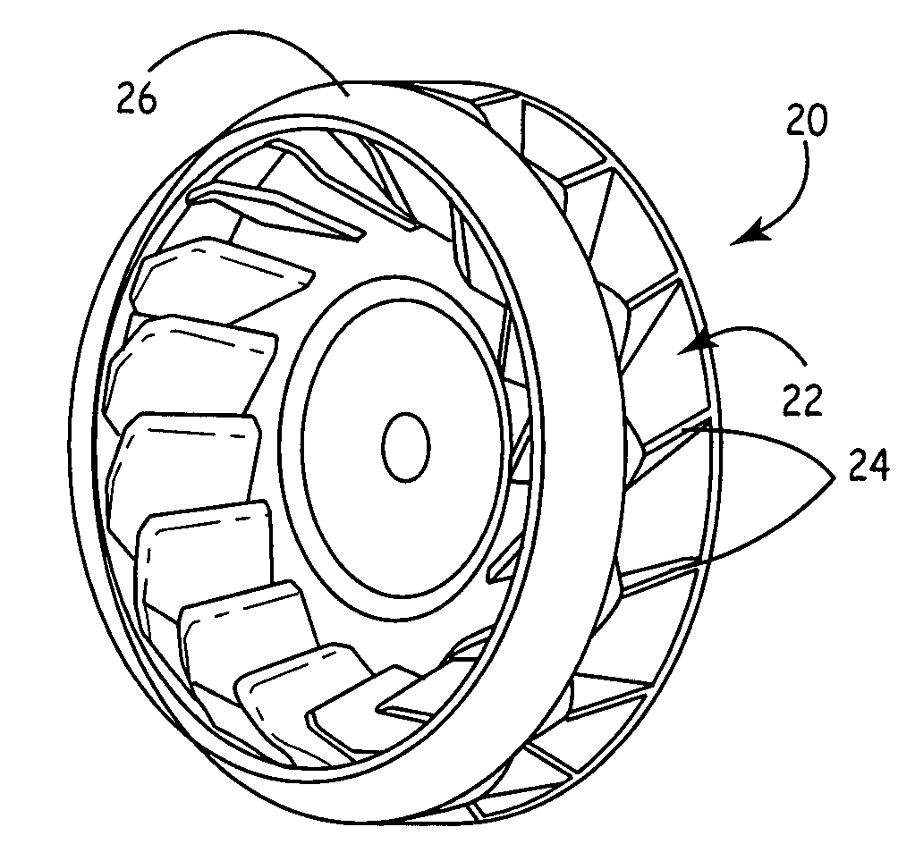
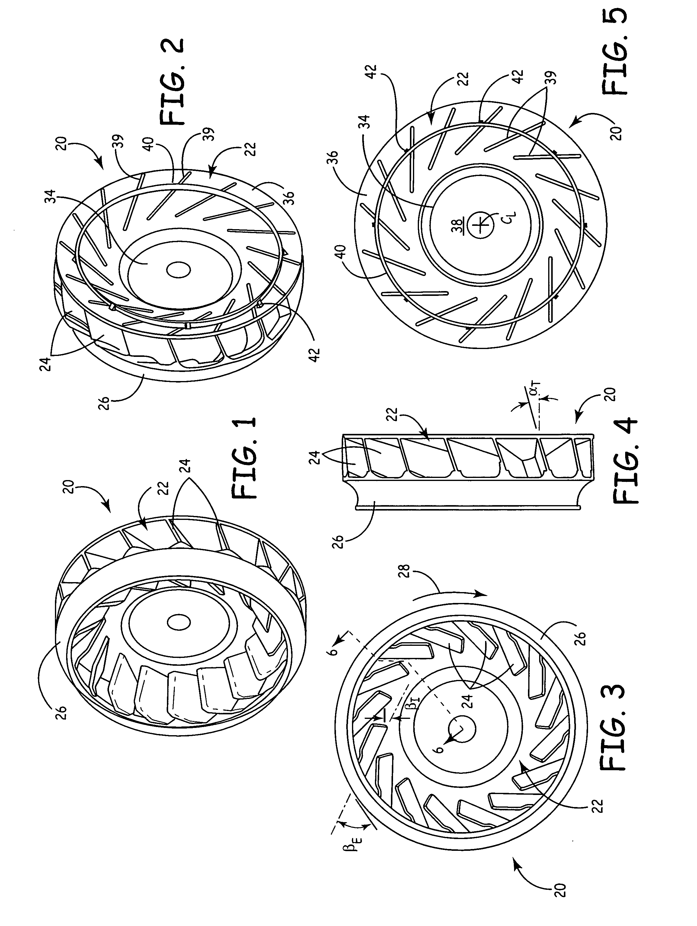
[0006] FIG. 1 is a perspective view of one embodiment of a fan apparatus of the present invention, viewed from the front.
[0007] FIG. 2 is a perspective view of the fan apparatus of FIG. 1, viewed from the rear.
[0008] FIG. 3 is a front elevation view of the fan apparatus of FIGS. 1 and 2.
[0009] FIG. 4 is a side elevation view of the fan apparatus of FIGS. 1-3.
[0010] FIG. 5 is a rear elevation view of the fan apparatus of FIGS. 1-4.
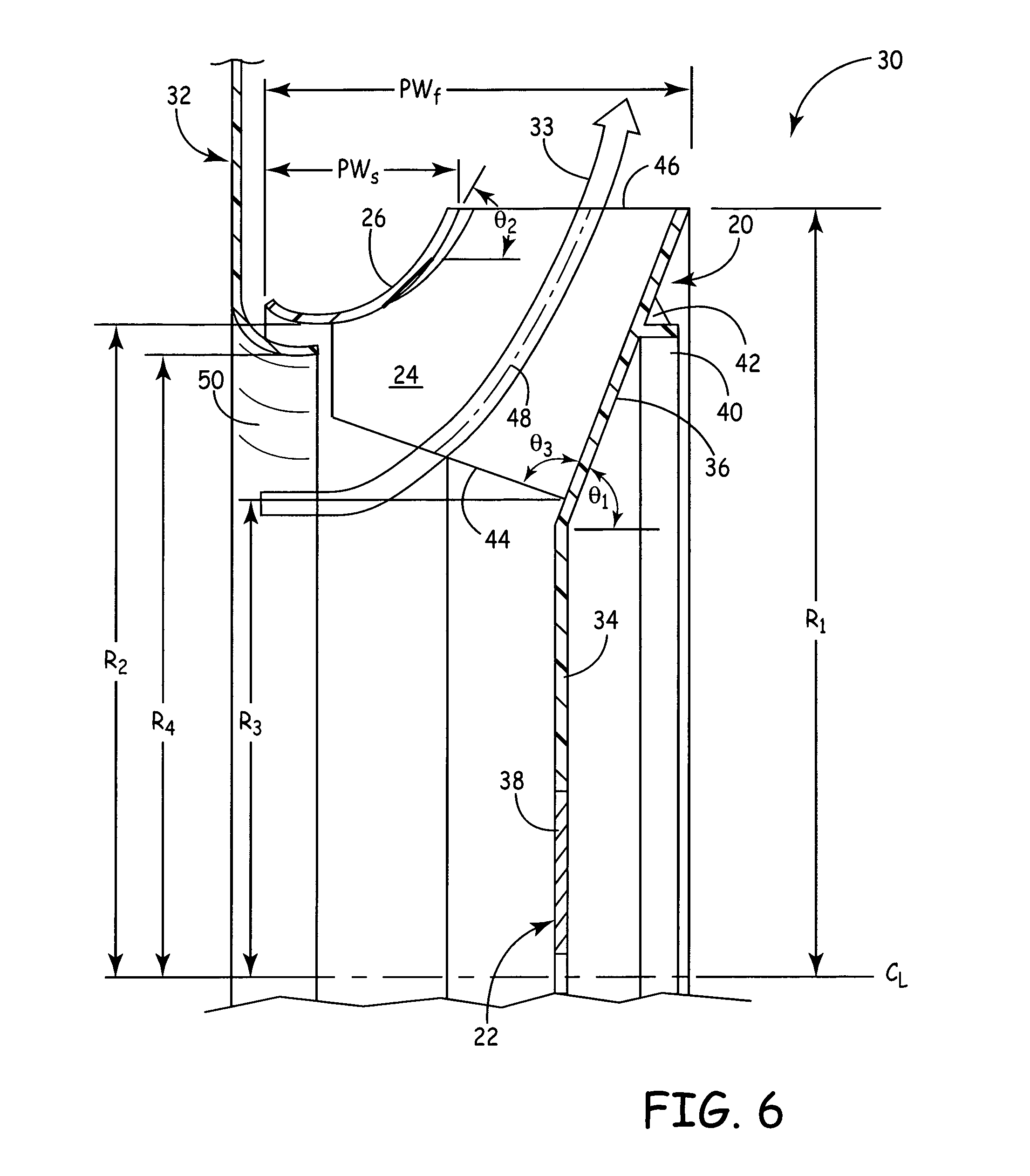
[0011] FIG. 6 is a cross-sectional view of a portion of a fan assembly according to the present invention.
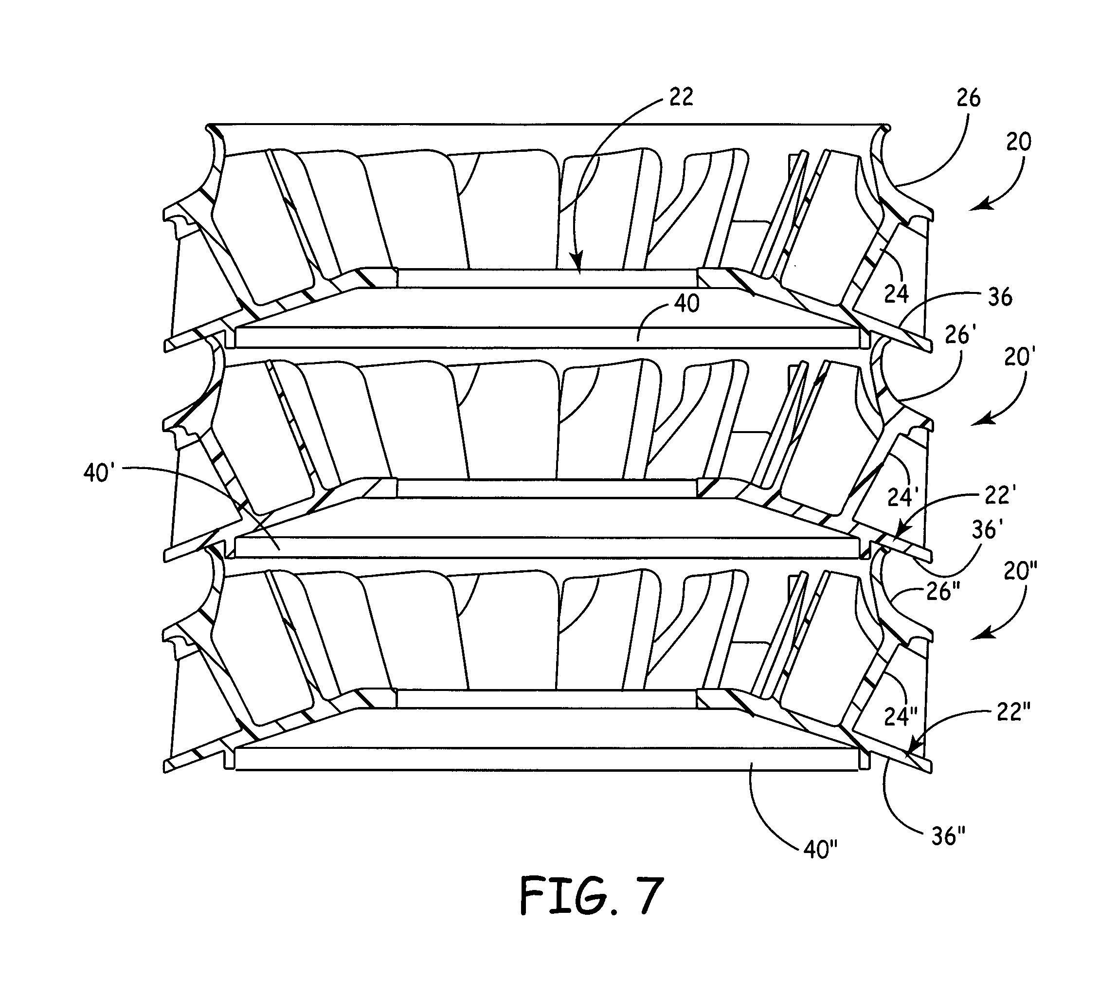
[0012] FIG. 7 is a cross-sectional view of a number of the fan apparatuses of FIGS. 1-6 in a stack.
[0013] FIG. 8 is a perspective view of a portion of the fan apparatus of FIGS. 1-6.
[0014] FIG. 9 is a schematic view of an alternative embodiment of a fan apparatus according to the present invention, shown with a fan shroud omitted.
[0015] FIG. 10 is a front elevation view of another alternative embodiment of a fan apparatus according to the present invention, shown with a fan shroud omitted.
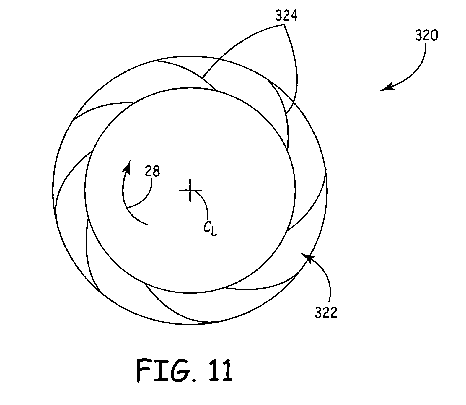
[0016] FIG. 11 is a front elevation view of yet another alternative embodiment of a fan apparatus according to the present invention, shown with a fan shroud omitted.
[0017] FIG. 12 is a graph of performance data for select alternative embodiments of the fan assembly.
[0018] While the above-identified drawing figures set forth several embodiments of the invention, other embodiments are also contemplated, as noted in the discussion. In all cases, this disclosure presents the invention by way of representation and not limitation. It should be understood that numerous other modifications and embodiments can be devised by those skilled in the art, which fall within the scope and spirit of the principles of the invention. The figures may not be drawn to scale. Like reference numbers have been used throughout the figures to denote like parts.
DETAILED DESCRIPTION
[0019] The present invention claims priority to U.S. Provisional Patent Application No. 61/066,692 entitled "High Efficiency Hybrid Flow Fan," filed Feb. 22, 2008, which is hereby incorporated by reference in its entirety.
[0020] In general, the present invention provides a quasi-mixed (or hybrid) flow fan (generally referred to herein simply as a hybrid flow fan), enabling the generation of fluid flow in a hybrid radial and axial direction (i.e., somewhere in between 0 and 90.degree. with respect to the axial direction) in response to rotational input. In one embodiment, the fan has an overall depth (i.e. thickness or width) of approximately 20-35% of an overall fan diameter. The fan of the present invention can be used in engine cooling systems, preferably when operating in a range of fan throttling coefficients from approximately 0.04 to 0.08, where throttling coefficient is defined as a ratio of velocity pressure to total pressure, with the velocity pressure calculation based on a superficial velocity equal to airflow divided by an axial projected area of the fan.
[0021] The fan of the present invention provides numerous advantages and benefits. For example, the fan provides a relatively high airflow and relatively high pressure fan for engine cooling. However, configuration of the fan is generally subject to several constraints for use with automotive and other engine cooling applications. The fan should preferably be mounted on the front of an engine in the same manner as existing axial flow fans (e.g., belt-driven or crankshaft mounted). Further, the fan should allow use of a viscous fan clutch (also called a viscous fan drive), a device that allows speed control of the fan and helps isolate the fan from crankshaft torsional vibration. An overall diameter of the fan should preferably be comparable to existing axial flow fans. A thickness (i.e., axial depth) of the fan should ideally be comparable to existing axial flow fans, or as thin (i.e., axially narrow) as possible because additional engine compartment space is often difficult or impossible to allocate. An inlet diameter of the fan should preferably be as large as possible to prevent high high-velocity airflows in the center of radiators or other heat exchangers that can result in detrimental airflow stratification through radiator and heat exchanger cores. Airflow discharge from the fan should preferably have an axial component to help guide the air around sides of and past the engine. Static efficiency of the fan should be as high as possible, and preferably greater than 50%, to maximize the engine power available for useful work. Noise produced by the fan should be as low as possible, and preferably no louder than that of existing axial-flow fans operating with lesser aerodynamic performance. Also, an interface (i.e., shrouding) between an inlet to the fan and the radiator or other heat exchangers should accommodate relative motion between the two caused by engine rocking and frame twisting, yet be made of structures achievable by ordinary assembly-line procedures.
[0022] Several of the constraints discussed above appear mutually exclusive. The inlet diameter of the fan is one such example. Generally, in a radial flow (or centrifugal) fan, greater pressure production is achieved by decreasing a ratio of blade inside diameter to blade outside diameter, thus making fan blades longer in a radial direction. Doing so, however, decreases an axial inlet area of the fan, increasing inlet velocity. Because spacing between a vehicle radiator (or other heat exchanger) and fan is typically short, such high velocity fluid flow directly in front of the fan would likely create undesirable "dead zones" in corners of the radiator (or other heat exchanger), thereby decreasing overall heat exchange efficiency. Similarly, high airflow in a radial flow (or centrifugal) fan is typically achieved by increasing the fan's axial depth, an option not available for under-hood engine cooling applications. It was necessary, therefore, in designing the fan of the present invention to create a fan with design parameters that produced a suitably efficient fan under a host of constraints. In general, the fan of the present invention tends to exhibit relatively high airflow and static efficiency characteristics while still satisfying the constraints discussed above.
[0023] FIGS. 1-5 illustrate various views of one embodiment of a fan apparatus 20. FIG. 1 is a perspective view of the fan apparatus 20, viewed from the front, and FIG. 2 is a perspective view of the fan apparatus 20, viewed from the rear. FIGS. 3-5 are front, side and rear elevation views, respectively, of the fan apparatus 20. As shown in FIGS. 1-5, the fan apparatus 20 includes a backplate 22, a plurality of blades 24 (also called airfoils), and a fan shroud 26 arranged for rotation about a centerline C.sub.L. The backplate 22, the blades 24 and the fan shroud 26 are collectively referred to as the fan subassembly. As shown by arrow 28 in FIG. 3, the illustrated fan apparatus 20 is configured to rotate in a clockwise direction, though it should be understood that the fan apparatus 20 can be configured to rotate in a counterclockwise direction in alternative embodiments.
[0024] Those of ordinary skill in the art will appreciate that in one embodiment the fan apparatus 20 is attached to a suitable clutch (not shown), such as a viscous clutch of the type disclosed in PCT Published Application No. WO 2007/016497 A1, and in turn operatively connected to an engine (not shown). The clutch is typically removably secured to the backplate 22 of the fan apparatus 20 with bolts or other suitable attachment means. The engine and clutch can selectively rotate the fan apparatus 20 at a desired speed, with the fan apparatus 20 moving air to help cool the engine. In a typical application, the fan apparatus 20 is positioned between a radiator and/or other heat exchangers (not shown) and the engine, with fan operation both directing cooling air to the engine and moving air through the radiator (and/or other heat exchangers) to further provide cooling.
[0025] FIG. 6 is a cross-sectional view of a portion of a fan assembly 30 that includes the fan apparatus 20 and an inlet shroud 32. For simplicity, only one of the blades 24 of the fan assembly 30 is illustrated in FIG. 6. Fluid flow generated by the fan assembly 30 during operation is illustrated by arrow 33, which exits the fan apparatus 20 in a hybrid radial and axial direction (i.e., in between 0 and 90.degree. with respect to the centerline C.sub.L). It should be noted that airflow generated by the fan apparatus 20 in a hybrid radial and axial direction is particularly beneficial for under-hood automotive applications. Such a hybrid airflow orientation is often more desirable than purely axial or radial airflows for under-hood cooling applications, because it tends to direct airflow around and past the engine for better cooling.
[0026] The backplate 22 includes a substantially planar inner diameter (ID) portion 34 (also called a hub) and a frusto-conical outer diameter (OD) portion 36. The ID portion 34 is arranged generally perpendicular to the centerline C.sub.L of the fan apparatus 20. A metallic disk 38 (e.g., made of steel, aluminum, etc.) is optionally incorporated into the ID portion 34 at the centerline C.sub.L to provide a relatively rigid structure for attachment of the fan apparatus 20 to a clutch or other rotational input source (not shown). One or more openings are optionally provided in the metallic disk 38 in the ID portion 34 at or near the centerline C.sub.L to facilitate attachment to the clutch or other rotational input source. The ID portion 34 is sufficiently large to accommodate attachment to a clutch. Prior art mixed flow fans tend to have an ID portion that is too small for mounting to a conventional automotive fan clutch. The OD portion 36 is positioned directly adjacent to and radially outward from the ID portion 34. The OD portion 36 is arranged at an angle .theta..sub.1 with respect to the centerline C.sub.L. Generally, a discharge angle of the airflow 33 exiting the fan apparatus 20 is equal to the angle .theta..sub.1. In the illustrated embodiment, the OD portion 36 extends to a perimeter (i.e., circumference) of the fan assembly 20. The backplate 22 has a radius R.sub.1, which defines a corresponding overall diameter oD1. For common applications, values of the diameter oD1 range from about 450 mm to about 750 mm, though it will be appreciated that the diameter oD1 can have essentially any value greater than zero as desired for particular applications.
[0027] In the illustrated embodiment, a groove 39 is formed in the rear side of the backplate 22 corresponding to and aligned with each one of the blades 24. The grooves 39 help reduce thickness of the backplate 22 and an overall mass of the fan apparatus 20. The grooves 39 are optional, and generally are only present when the backplate 22 and the blades 24 are integrally molded during fabrication. When the backplate 22 is injection molded, the grooves 39 also help avoid sink marks, which are molding defects that occur due to volume shrinkage during cooling. Fabrication of the fan apparatus 20 is discussed further below.
[0028] An annular rib 40 extends generally axially from the backplate 22 at a rear side of the backplate 22 opposite the blades 24 (see FIGS. 2, 5 and 6). In the illustrated embodiment, the annular rib 40 extends generally axially from the OD portion 36 of the backplate 22, at a location in between the perimeter of the backplate 22 and the ID portion 34. Also, the annular rib 40 is axially recessed relative to the perimeter of the backplate 22. A suitable number of gussets 42 (e.g., eight) are provided between the annular rib 40 and the backplate 22 to provide structural support. In the illustrated embodiment, the gussets 42 are circumferentially spaced from one another and located at an OD face of the annular rib 40. Balancing weights (not shown) are optionally attached to the annular rib 40 to help balance the fan apparatus 20 during operation. In one embodiment, balancing weights of a known configuration are adhesively secured at an ID face of the annular rib 40, such that the annular rib 40 helps to radially retain the weights during fan operation. The annular rib 40 can further provide increased stiffness to the fan apparatus 20.
[0029] FIG. 7 is a cross-sectional view of three fan apparatuses 20, 20' and 20'' in a stack. Any number of fan apparatuses 20, 20' and 20'' can be stacked together in further embodiments. As shown in FIG. 7, each of the fan apparatuses 20, 20' and 20'' has an identical configuration and are designated with similar reference numbers, though reference numbers for components of the fan apparatus 20' carry a prime designation and reference numbers for components of the fan apparatus 20'' carry a double prime designation. When stacked, the fan shrouds 26' and 26'' of the fan apparatuses 20' and 20'' extend into a pocket defined between the ribs 40 and 40' and the OD portions 36 and 36' of the backplates 22 and 22' of the adjacent fan apparatus 20 or 20'. Moreover, the ribs 40 and 40' of the fan apparatuses 20 and 20' are positioned radially inward from the fan shrouds 26' and 26'' of the adjacent fan apparatus 20' or 20'', and the backplates 22 and 22' contact the adjacent fans shroud 26' or 26''. In this way, the fan apparatuses 20, 20' and 20'' can be relatively easily aligned in a stack for storage or transport, and the stack is relatively compact and stable enough to resist falling over. The stack can optionally be placed in a suitable container (not shown) for storage or transport.
[0030] Turning again to FIGS. 1-6, the fan shroud 26 is secured to each of the blades 24 opposite the backplate 22, and rotates with the fan apparatus 20 during operation. In the illustrated embodiment, the fan shroud 26 has a generally annular shape, and is at least partially curved in a toroidal, converging-diverging configuration. An ID portion of the fan shroud 26 curves away from the backplate 22. The fan shroud 26 is generally secured to OD portions of the blades 24. As shown in FIG. 6, the fan shroud 26 defines a projected width PW.sub.s (measured between axially forward and rear extents of the fan shroud 26) and an inlet radius R.sub.2 (measured between the centerline C.sub.L and a radially inward extent of the fan shroud 26), with the radius R.sub.2 defining a corresponding diameter oD2. In an exemplary embodiment, the diameter oD2 is about 85% of the diameter oD1. In one embodiment, the projected width PW.sub.s is about 12% of the diameter oD1. An OD portion of the fan shroud 26 is oriented at an angle .theta..sub.2 with respect to the centerline C.sub.L.
[0031] The blades 24 extend from the OD portion 36 of the backplate 22 to the fan shroud 26. In the illustrated embodiment, a total of sixteen blades 24 are provided, though the number of blades 24 can vary in alternative embodiments (e.g., a total of eighteen blades 24, etc.). Each blade 24 defines a leading edge 44, which is oriented at an angle .theta..sub.3 relative to the OD portion 36 of the backplate 22, and a trailing edge 46, which is arranged substantially parallel to the centerline C.sub.L in the illustrated embodiment. Those skilled in the art will appreciate that opposite pressure and suction sides of the blades 24 extend between the leading and trailing edges 44 and 46. In the illustrated embodiment the leading edges 44 of the blades 24 are not attached to the fan shroud 26. The leading edges 44 of the blades 24 collectively define a radius R.sub.3 about the centerline C.sub.L, which corresponds to a blade inner diameter oD.sub.3. Because the blades 24 extend along the frusto-conical OD portion 36 of the backplate 22, the radial locations of the leading edges 44 of the blades 24 affect the center of mass of the fan apparatus 22 in the axial direction. It is generally desirable to locate the center of mass at an axially middle location to better balance the fan apparatus 20 during operation, particularly with respect to bearings of a clutch to which the fan apparatus 20 can be mounted. In some embodiments, the ID portion 34 is substantially aligned with the center of mass of the fan apparatus 20 (e.g., within approximately +/-2% of the overall diameter oD1 relative to the center of mass in the axial direction). Furthermore, each blade defines an inlet angle .beta..sub.1 and an exit angle .beta..sub.E (see FIG. 3). The inlet angle .beta..sub.1 for each blade 24 is defined between a tangent line at the leading edge 44 and to a blade mean thickness line at the leading edge 44. The exit angle .beta..sub.E is defined between a tangent line located at the trailing edge 46 and a mean thickness line of the blade 24 at the trailing edge 46. Each blade 24 is oriented at a tilt angle .alpha..sub.T with respect to a line normal to the OD portion 36 of the backplate 22 (i.e., a line parallel to the centerline C.sub.L) (see FIG. 4). The blades 24 are tilted in a direction into the direction of rotation of the fan apparatus 20 designated by the arrow 28 in FIG. 3. It should be noted that the blades 24 can be essentially axially oriented with the tilt angle .alpha..sub.T equal to zero in some embodiments.
[0032] The blades 24 in the embodiment of the fan apparatus 20 shown in FIGS. 1-6 are configured in a backward inclined arrangement. Those skilled in the art will recognize that as a function of the relationship between the inlet angle .beta..sub.1 and the exit angle .beta..sub.E, fan blades can be configured in backward curved, backward inclined, radial (or quasi-radial) tip, forward curved, and radial blade arrangements. In various alternative embodiments, any desired configuration of the blades is utilized (see, e.g., FIGS. 9 and 10). Moreover, if the intended direction of rotation designated by the arrow 28 were to change (i.e., from clockwise to counterclockwise), the arrangement of the blades 24 for a particular configuration would be reversed (i.e., as a mirror image).
[0033] As shown in FIG. 6, a meridional streamline 48 is projected on the illustrated blade 24. The meridional streamline 48 is defined by a center or midpoint of a volume of fluid between the backplate 22 and the fan shroud 26 between two adjacent blades 24 from an inlet at the leading edge 44 of the blades 24 to an outlet at the trailing edge 46 of the blades 24. The meridional streamline 48 is generally a curve or arc that relates to the fluid flow illustrated by the arrow 33. Each of the blades 24 has a meridional length defined along its respective projected meridional streamline 48. A total blade length L.sub.Btot is defined as the cumulative length obtained by adding together the meridional lengths of each of the blades 24 of the fan apparatus 20. The total blade length L.sub.Btot is affected by the number of blades 24 that the fan apparatus 20 includes, as well as by dimensions of the individual blades 24.
[0034] The fan apparatus 20 defines a projected width PW.sub.f (i.e., an overall depth or thickness) in the axial direction. In the illustrated embodiment, the projected width PW.sub.f is defined between the axially forward extent of the fan shroud 26 and an axially rear extent of the OD portion 36 of the backplate 22. In one embodiment, the overall diameter oD1 of the fan apparatus 20 is approximately 550 mm and the projected with PW.sub.f of the fan apparatus 20 is approximately 165 mm. While the fan apparatus 20 is generally thicker (i.e., deeper in the axial direction) than a conventional axial flow fan, the fan apparatus 20 can have a thickness of only about 180-200% relative to the thickness of a conventional axial flow fan compared to about 250% for prior art mixed flow fans and about 300% for prior art radial flow fans.
[0035] The inlet shroud 32 is an annular member positioned adjacent to the fan apparatus 20, and includes an ID portion 50 that is at least partially curved in a toroidal configuration. The inlet shroud 32 defines an upstream opening that is larger than a downstream opening. Typically, the inlet shroud 32 is rotationally fixed, and in under-hood applications can be secured to an engine, a radiator or other heat exchanger, a vehicle frame, etc. The inlet shroud defines a radius R.sub.4 at a radially inward extent of the ID portion 50, with the radius R.sub.4 corresponding to a diameter oD.sub.4. In the illustrated embodiment, at least part of the ID portion 50 of the inlet shroud 32 is positioned within an upstream portion of the fan shroud 26, and extends rearward of the axially forward extent of the fan shroud 26. In other words, an axial overlap is formed between the fan shroud 26 and the inlet shroud 32. A generally radial gap is present between the fan shroud 26 and the inlet shroud 32, which, in under-hood applications, allows for relative movement between those components due to engine rocking, frame twisting, vibration or other movements. During operation, fluid flow in the direction of the arrow 33 passes through a central opening of the inlet shroud 32 to the fan apparatus 20. The inlet shroud 32 can help guide airflow to the fan apparatus 20 from a radiator or other heat exchanger. Also, some additional fluid flow may reach the fan apparatus 20 through the generally radial gap between the fan shroud 26 and the inlet shroud 32.
[0036] The configuration of the fan apparatus 20 according to the present invention can vary as desired for particular applications. Table 1 provides three possible ranges for parameters of the fan apparatus 20. The values given in Table 1 are all approximate. It should also be noted that the values in Table 1 are provided merely by way of example and not limitation. Moreover, Table 1 should be interpreted to allow independent selection of individual parameters. For instance, one parameter can be selected from the "first range" column while another parameter can be selected from the "second range" column, and so forth.
TABLE-US-00001 TABLE 1 Parameter First Range Second Range Third Range OD1 up to .infin. 680 mm 550 mm (equal to twice R.sub.1) OD2(equal to 80-90% of OD1 82-88% of OD1 84-86% of OD1 twice R.sub.2) OD3(equal to twice R.sub.3) 50-75% of OD1 55-70% of OD1 58-65% of OD1 OD4 <OD2 OD2 - x, where x is (equal to twice R.sub.4) about 12-24 mm .theta..sub.1 65-80.degree. 67-75.degree. 68-70.5.degree. .theta..sub.2 50-80.degree. 60-70.degree. .theta..sub.3 90.degree. .beta..sub.I 15-30.degree. 18-28.degree. 20-25.degree. .beta..sub.E 40-90.degree. 50-80.degree. 55-70.degree. .alpha..sub.T 0-15.degree. 3-10.degree. 4-6.degree. PW.sub.f 20-35% of OD1 25-35% of OD1 28-32% of OD1 PW.sub.s 10-15% of OD1 12-13% of OD1 L.sub.Btot 450-550% of OD1 450-550% of OD1 480-520% of OD1
[0037] FIG. 8 is a perspective view of a portion of the fan apparatus 20. As shown in FIG. 8, an optional fillet 52 is located between the blade 24 and the fan shroud 26. The blade 24 has an unattached tip portion 54 adjacent to the leading edge 44. In the illustrated embodiment, the fillet 52 is integrally formed with the blade 24, and extends in a generally chordwise direction from the unattached tip portion 54 of the blade 24 to the fan shroud 26, facing generally radially inward. The fillet 52 physically contacts the fan shroud 26, and can optionally be joined to the fan shroud 26. The fillet 52 is optionally provided on each of the blades of the fan apparatus 20, and can be omitted entirely in alternative embodiments. The presence of the fillet 52 helps to reduces stresses at the interface between each blade 24 and the fan shroud 26.
[0038] The fan assembly 30, including the fan apparatus 20, can be manufactured in a variety of ways. Typically components of the fan assembly 30 are made of a polymer or other injection-moldable material, though fiberglass, metals and other suitable materials can alternatively be used. In one embodiment, injection molding is utilized, in which a polymer material, such as nylon, forms essentially all of the components of the fan assembly 30, except for the metallic disk 38, which can be made of steel. The blades 24 and the backplate 22 are usually integrally formed as a single subassembly. If the blades 24 and backplate 22 are injection molded, the metallic disk 38 can be overmolded with the polymer material to integrally form the blades 24 and the backplate 22. The fan shroud 26 and the inlet shroud 32 are generally each separately formed by injection molding or other suitable techniques. The fan shroud 26 is then attached to the blades 24 of the subassembly, using a welding process, mechanical fasteners or other suitable techniques. A welding or welding-like process, such as ultrasonic welding or high frequency electromagnetic welding and bonding, is preferred. A configuration with welded joints between the blades 24 and the fan shroud 26 produces relatively low stresses on the weld joints between the blades 24 and the fan shroud 26, while simplifying the process of injection molding the individual parts that are later welded together. The inlet shroud 32 is separately attached to a mounting structure, and the fan apparatus 20 is positioned adjacent to the inlet shroud 32 in a desired installation location.
[0039] In other embodiments, the backplate 22, the blades 24 and the fan shroud 26 of the fan apparatus 20 are integrally molded as a single piece. While a single-piece construction offers strength benefits, it tends to require complex and expensive dies to achieve. Alternatively, the fan shroud 26 and the blades 24 are integrally molded and attached to a separately molded backplate 22.
[0040] As previously mentioned, a fan apparatus according to the present invention can have its blades arranged in a number of different configurations in alternative embodiments, such as backward curved, backward inclined, radial (or quasi-radial) tip, forward curved, and radial blade configurations. Those terms are derived from radial flow fan design. Different blade configurations will have different operational effects, which are generally interrelated to other fan apparatus parameters. The optimal blade configuration will vary for different applications depending on the desired performance characteristics and constraints on the design of the fan apparatus. FIGS. 9 and 10 illustrate two additional blade configurations, though it will be appreciated that others are possible within the scope of the present invention.
[0041] FIG. 9 is a schematic view of an alternative embodiment of a fan apparatus 120 that includes a backplate 122 and a plurality of blades 124, and is configured to rotate in the direction of the arrow 28 (i.e., clockwise). The fan apparatus 120 also includes a fan shroud secured to the blades 124 that is omitted in FIG. 9 to better reveal the blades 124. The general configuration and operation of the fan apparatus 120 is similar to that of the fan apparatus 20 described above. In the illustrated embodiment, the blades 124 of the fan apparatus 120 are arranged in a forward curved configuration.
[0042] FIG. 10 is a front elevation view of another alternative embodiment of a fan apparatus 220 that includes a backplate 222 and a plurality of blades 224, and is configured to rotate in the direction of the arrow 28 (i.e., clockwise). The fan apparatus 220 also includes a fan shroud secured to the blades 224 that is omitted in FIG. 10 to better reveal the blades 224. The general configuration and operation of the fan apparatus 220 is similar to that of the fan apparatus 20 described above. In the illustrated embodiment, the blades 224 of the fan apparatus 220 are arranged in a quasi-radial tip configuration. In a true radial tip configuration, blades are curved such that their trailing edges are arranged exactly radially. However, in the illustrated quasi-radial tip configuration, the blades 224 are curved with trailing edges 246 of the blades 224 arranged close to radially, but not exactly radially.
[0043] FIG. 11 is a front elevation view of yet another alternative embodiment of a fan apparatus 320 that includes a backplate 322 and a plurality of blades 324, and is configured to rotate in the direction of the arrow 28 (i.e., clockwise). The fan apparatus 320 also includes a fan shroud secured to the blades 324 that is omitted in FIG. 11 to better reveal the blades 324. The general configuration and operation of the fan apparatus 320 is similar to that of the fan apparatus 20 described above. In the illustrated embodiment, the blades 324 of the fan apparatus 220 are arranged in a backward curved configuration.
[0044] In view of the foregoing description, those skilled in the art will recognize that a fan assembly according to the present invention provides numerous advantages and benefits. For example, a fan according to the present invention provides relatively high pressure and airflow but is relatively thin and generally exhibits a different aspect ratio than what a designer would otherwise produce with the luxury of substantial axial depth space available. Moreover, the fan of the present invention exhibits relatively good operating static efficiency characteristics. The fan of the present invention can also meet desired performance characteristics for under-hood automotive cooling applications while simultaneously satisfying the many design limitations associated with under-hood applications.
[0045] In addition, a fan according to the present invention provides relatively good noise characteristics, including both noise intensity and noise quality characteristics. The fairest comparison of noise between two fan types is when both are operating at the same aerodynamic point (i.e. same flow and pressure). Comparing a 680 mm diameter fan of the present invention running 1900 RPM to a prior art 750 mm diameter axial flow fan running at 1970 RPM, the fan of the present invention was 4 dBA quieter. The fan of the present invention is quieter for two major reasons. First, the fan of the present invention can develop a desired level of static pressure at a slower rotational speed compared to an axial flow fan, and fan noise is very strongly dependent upon peripheral speed (i.e., tip speed). Second, flow of air through passages of the fan of the present invention is much smoother and much less turbulent than the flow of air through an axial flow fan at the high pressures at which the fan of the present invention is desired to operate. Typically, flow through an axial flow fan under the conditions described above is known as stalled flow, which is highly turbulent and unstable, and is associated with a roaring noise.
[0046] Additional advantages and benefits not specifically mentioned are also provided.
EXAMPLES
[0047] Prototype fan assemblies according to the present invention were developed and tested, and computer simulations were run to further explore fan assembly designs according to the present invention. Prototype testing has shown that a fan according to the present invention can achieve about 35% higher airflow, 15 percentage-points greater static efficiency and exhibit quieter operating characteristics than state-of-the art axial flow fans, while still being suitable for installation in under-hood automotive cooling applications and exhibiting acceptable power requirements.
[0048] A design of experiments (DOE) protocol was employed to run simulations of a number of permutations of a number of judiciously selected fan design variables. The DOE allows for optimization while conducting tests on only a limited number of possible permutations. Computational fluid dynamics (CFD) software (e.g., FLUENT.RTM. flow modeling software available from ANSYS, Inc., Santa Clara, Calif.) was utilized to generate simulation test data according to each DOE. Multiple DOE studies were conducted. The largest DOE conducted involved five factors with three possible levels each, for a total of 243 (or 3.sup.5) possible combinations, of which 27 variations were simulated in accordance with the selections of factors and levels listed in Table 2.
TABLE-US-00002 TABLE 2 Factor Levels .beta..sub.I 20.degree. - 28.degree. - 33.degree. .beta..sub.E Backward Curved (30-55.degree.) - Backward Inclined (55-65.degree.) - Forward Curved (65-80.degree.) OD3 325 mm - 400 mm - 475 mm .theta..sub.1 60.degree. - 70.degree. - 80.degree. PW.sub.f 175 mm - 205 mm - 235 mm Tilt angle 0.degree. .theta..sub.3 90.degree. Number of Blades 16 OD1 680 mm Blade Thickness 3 mm
[0049] Results of the DOE were gathered for airflow rate (in kg/s), static pressure (in Pa) and static efficiency (in %). FIG. 12 is a graph of performance data for select alternative embodiments of the fan assembly 20 according to the largest DOE. The graph of FIG. 12 denotes airflow (kg/s) along the horizontal axis vs. pressure (Pa) along the left-hand vertical axis and static efficiency (%) along the right-hand vertical axis. The 27 DOE results for static efficiency vs. airflow are plotted in FIG. 12 with hollow squares, and results for pressure vs. airflow are plotted in FIG. 12 with solid diamonds. It should be noted that each hollow square is vertically aligned with a corresponding solid diamond in FIG. 12.
[0050] The results for pressure vs. pressure vs. airflow data points (solid diamonds) were specified to fall upon a quadratic curve that approximates a typical engine cooling restriction curve. The DOE results show that the corresponding static efficiency vs. airflow data points (hollow squares) collectively define a boundary curve 400. Based on the 27 DOE results, data points were interpolated for three optimized designs of the fan apparatus 20. For a design #1, performance was optimized for both best airflow and best static efficiency, illustrated in FIG. 12 for static efficiency as a hollow triangle and for pressure as a solid triangle. For a design #2, performance was optimized for best static efficiency, illustrated in FIG. 12 for static efficiency as a hollow circle and for pressure as a solid circle. For a design #3, performance was optimized from best airflow, illustrated in FIG. 12 for static efficiency as a hollow hexagon and for pressure as a solid hexagon. Parameters for the fan apparatus 20 associated with designs #1-3 are provided in Table 3. Interaction between parameters of the fan apparatus 20 is not intuitive and is time-consuming to determine by physical prototype builds and testing. Each of the designs #1-3 is feasible and may satisfy different engine cooling applications with different requirements.
TABLE-US-00003 TABLE 3 Parameter Design #1 Design #2 Design #3 .beta..sub.I 23.degree. 22.degree. 30.degree. .beta..sub.E 50.degree. (Backward 43.degree. (Backward 78.degree. (Forward Curved) Curved) Curved) OD3 366 mm 413 mm 350 mm .theta..sub.1 75.degree. 73.degree. 78.degree. PW.sub.f 224 mm 219 mm 235 mm
[0051] Although the present invention has been described with reference to preferred embodiments, workers skilled in the art will recognize that changes may be made in form and detail without departing from the spirit and scope of the invention.
* * * * *
D00000
D00001
D00002
D00003
D00004
D00005
D00006
D00007
D00008
XML
uspto.report is an independent third-party trademark research tool that is not affiliated, endorsed, or sponsored by the United States Patent and Trademark Office (USPTO) or any other governmental organization. The information provided by uspto.report is based on publicly available data at the time of writing and is intended for informational purposes only.
While we strive to provide accurate and up-to-date information, we do not guarantee the accuracy, completeness, reliability, or suitability of the information displayed on this site. The use of this site is at your own risk. Any reliance you place on such information is therefore strictly at your own risk.
All official trademark data, including owner information, should be verified by visiting the official USPTO website at www.uspto.gov. This site is not intended to replace professional legal advice and should not be used as a substitute for consulting with a legal professional who is knowledgeable about trademark law.