Inlet Guide Vane for a Gas Compressor
Nilsson; Ulf
U.S. patent application number 12/864288 was filed with the patent office on 2010-12-30 for inlet guide vane for a gas compressor. Invention is credited to Ulf Nilsson.
| Application Number | 20100329851 12/864288 |
| Document ID | / |
| Family ID | 39473414 |
| Filed Date | 2010-12-30 |


| United States Patent Application | 20100329851 |
| Kind Code | A1 |
| Nilsson; Ulf | December 30, 2010 |
Inlet Guide Vane for a Gas Compressor
Abstract
An inlet guide vane for a compressor is provided. The inlet guide vane is adjustable to modify gas flow properties in the compressor, wherein electroactive polymers are arranged in the inlet guide vane such that the shape of the inlet guide vane is adjusted in a specified manner upon applying a voltage to the inlet guide vane.
| Inventors: | Nilsson; Ulf; ( Leicester, GB) |
| Correspondence Address: |
    SIEMENS CORPORATION;INTELLECTUAL PROPERTY DEPARTMENT
    170 WOOD AVENUE SOUTH
    ISELIN
    NJ
    08830
    US
|
| Family ID: | 39473414 |
| Appl. No.: | 12/864288 |
| Filed: | January 14, 2009 |
| PCT Filed: | January 14, 2009 |
| PCT NO: | PCT/EP2009/050368 |
| 371 Date: | July 23, 2010 |
| Current U.S. Class: | 415/151 |
| Current CPC Class: | F05D 2300/43 20130101; F02C 7/042 20130101; F04D 27/0246 20130101; F05D 2300/505 20130101; F04D 29/664 20130101; F04D 29/563 20130101; F05D 2250/51 20130101; F04D 29/4213 20130101; F04D 29/023 20130101; F01D 17/162 20130101; F01D 5/148 20130101; F04D 29/462 20130101 |
| Class at Publication: | 415/151 |
| International Class: | F04D 29/56 20060101 F04D029/56 |
Foreign Application Data
| Date | Code | Application Number |
|---|---|---|
| Jan 25, 2008 | EP | 08001433.5 |
Claims
1.-14. (canceled)
15. An inlet guide vane for a compressor, comprising: a plurality of electroactive polymers; wherein the inlet guide vane is adjustable in order to modify gas flow properties in the compressor, and wherein the plurality of electroactive polymers is arranged such that a shape of the inlet guide vane is adjusted in a specified manner upon applying a voltage to the inlet guide vane.
16. The inlet guide vane as claimed in claim 15, further comprising a fixed portion wherein the shape is maintained upon applying the voltage to the inlet guide vane.
17. The inlet guide vane as claimed in claim 16, wherein the fixed portion is located at a fore side.
18. The inlet guide vane as claimed in 17, wherein the fixed portion is located between a first portion at the fore side and a second portion at an aft side.
19. The inlet guide vane as claimed in claim 15, wherein at least a part of the plurality of electroactive polymers is located in a first layer extending in a longitudinal direction of the inlet guide vane.
20. The inlet guide vane as claimed in claim 19, wherein the first layer is covered with a flexible coating layer on at least one longitudinal side of the inlet guide vane.
21. The inlet guide vane as claimed in claim 20, wherein the flexible coating layer comprises a flexible metal layer and/or a flexible polymer layer.
22. The inlet guide vane as claimed in claim 20, wherein the flexible coating layer comprises a second layer of sound absorbent material.
23. The inlet guide vane as claimed in claim 19, wherein the first layer is laminated to the flexible coating layer.
24. The inlet guide vane as claimed in claim 15, wherein a surface of the inlet guide vane facing a wall of a channel of the compressor is of a generally spherical shape.
25. A compressor, comprising: an inlet guide vane, comprising: a plurality of electroactive polymers, wherein the inlet guide vane is adjustable in order to modify gas flow properties in the compressor, and wherein the plurality of electroactive polymers is arranged such that a shape of the inlet guide vane is adjusted in a specified manner upon applying a voltage to the inlet guide vane.
26. The compressor as claimed in claim 25, wherein the compressor is configured as a centrifugal compressor.
27. The compressor as claimed in claim 25, wherein the inlet guide vance further comprises a fixed portion wherein the shape is maintained upon applying the voltage to the inlet guide vane.
28. The compressor as claimed in claim 27, wherein the fixed portion is located at a fore side.
29. The compressor as claimed in 28, wherein the fixed portion is located between a first portion at the fore side and a second portion at an aft side.
30. The compressor as claimed in claim 25, wherein at least a part of the plurality of electroactive polymers is located in a first layer extending in a longitudinal direction of the inlet guide vane.
31. The compressor as claimed in claim 30, wherein the first layer is covered with a flexible coating layer on at least one longitudinal side of the inlet guide vane.
32. The compressor as claimed in claim 31, wherein the flexible coating layer comprises a flexible metal layer and/or a flexible polymer layer.
33. The compressor as claimed in claim 31, wherein the flexible coating layer comprises a second layer of sound absorbent material.
34. A turbocharger, comprising: a compressor, comprising: an inlet guide vane, comprising: a plurality of electroactive polymers, wherein the inlet guide vane is adjustable in order to modify gas flow properties in the compressor, and wherein the plurality of electroactive polymers is arranged such that a shape of the inlet guide vane is adjusted in a specified manner upon applying a voltage to the inlet guide vane.
Description
CROSS REFERENCE TO RELATED APPLICATIONS
[0001] This application is the US National Stage of International Application No. PCT/EP2009/050368, filed Jan. 14, 2009 and claims the benefit thereof. The International Application claims the benefits of European Patent Office application No. 08001433.5 EP filed Jan. 25, 2008. All of the applications are incorporated by reference herein in their entirety.
FIELD OF INVENTION
[0002] The invention relates to an inlet guide vane for a gas compressor, the vane being adjustable to modify gas flow properties in the compressor, as well as a compressor, turbocharger, and gas turbine therefor.
BACKGROUND OF INVENTION
[0003] In order to dynamically change the gas flow properties of the gas inlet of a compressor, it is known to use inlet guide vanes that can be turned so that the vanes are provided with a variable stagger or camber. U.S. Pat. No. 3,442,493 and U.S. Pat. No. 5,520,511 show vanes consisiting of two movable parts of fixed form.
[0004] In such implementations, the vanes are being manipulated, e.g., with the help of an annular ring to which each vane is coupled. The ring is acted upon by a lever or arm connected to an electric motor, or a hydraulic or pneumatic piston.
[0005] However, such arrangements require a number of moving parts, such as the actuators, rings, and linkage, which are subject to mechanical stress, wear, and environmental interferences, thus making such systems particularly vulnerable to mechanical failure.
[0006] EP 274293 A1 shows a turbocharger inlet vane comprising of two stable parts of which one is movably connected to the other. This solution generally shares the properties discussed before regarding its movable mechanical components.
[0007] U.S. Pat. No. 3,042,371 shows a turbocharger inlet vane which comprises a hollow body, the walls of which are of bimetal. Upon increase of temperature, the bimetallic walls change their shape so that the camber of the vane is varied. The temperature increase can be induced by an electric heating element embedded in the bimetallic wall. The heating elements may be operated by electrically.
[0008] U.S. Pat. No. 4,619,580 discloses a variable camber vane which is built up from a laminate which allows for a temperature-responsive deflection of the vane.
[0009] PCT patent application publication WO 2006/128827 A1 shows an air intake for a turbocharger for an internal combustion engine with inlet guide vanes made of sound absorbent materials to achieve a substantial reduction of noise.
[0010] PCT patent WO03/081762 A1 discloses several possibilities to use electroactive polymer, for example as a rotating blade of a fan.
[0011] PCT patent application WO2007/130847 A2 discloses the possibility to open and close an automobile grill using active materials.
[0012] US patent application 2006/0027703 A1 discloses winglets for improved rotor tip performance, which can also involve smart materials.
[0013] While this solution reduces the amount of mechanical moving parts, the acting elements are still exposed to wear by environmental stress, and the embedded heating elements provide for an additional source of error.
SUMMARY OF INVENTION
[0014] It is therefore an object of the present invention to provide an adjustable inlet guide vane that provides for improved reliability and reduced mechanical wear, as well as a compressor, turbocharger, and gas turbine therefor.
[0015] This object is achieved by the subject of the claims.
[0016] The invention according to the claims proposes an inlet guide vane for a compressor, the vane being adjustable to modify gas flow properties in the compressor, characterized in that the guide vane comprises electroactive polymers (EAPs) arranged such that the shape of the vane is adjusted in a specified manner upon applying a voltage to the guide vane. Suitable electroactive polymers are for example, disclosed in WO 2005/086249, U.S. Pat. No. 6,543,110, WO 2001/031715, and DE 10 2004 043 403. Regarding EAP materials which can be used in the inventive guide vane it is therefore referred to these documents.
[0017] When voltage is applied to the EAPs in the vane, the EAPs change their shape such that the vane bends and, consequently, changes its stagger and/or camber. EAPs can be activated directly by applying the respective level of voltage, and thus avoids the use of heating elements, further simplifying electronic control of the vane properties.
[0018] The use of EAPs allows for a great variety of configurations in which the shaping element or elements is included in the vane. EAPs can be laminated to a vane substrate, or can be finely distributed in a vane material. EAPs can further be included as capsular elements, laid or knitted fibres. Voltage can be supplied to the EAPs by electric leads, or by using electrically conductive vane materials.
[0019] There are, in general, two groups of EAPs which can be used in the inventive guide vane, namely ionic EAPs in which the acuation is caused by a displacement of ions inside the polymer, and dielectric EAP in which actuation is caused by electrostatic forces between two electrodes which squeeze the polymer. If ionic EAPs are used for the vane, the present invention can profit from the low voltage levels required for proper operation while achieving large bending displacements. However, the use of dielectric EPAs is also possible.
[0020] Consequently, the present invention allows to reduce the amount of mechanical parts needed for vane shape variation to a minimum, while providing for immediate electronic controllability, and thus significantly enhances the reliability of operation and simplifies its practical application in compressors.
[0021] The invention can be further embodied according to the features provided in the dependent claims.
[0022] In an embodiment, the inlet guide vane comprises a fixed portion which maintains its shape upon applying the voltage to the guide vane. Such a fixed portion may be implemented by isolating said portion of the vane from the voltage applied, so that no shaping is effected therein, or a different, dimensionally stable material may be used in the fixed portion.
[0023] In such embodiments, the fixed portion can be located at a fore side (leading edge, upstream edge), or can be located between a first portion at a fore side and a second portion at an aft side (trailing edge, downstream edge). Said first and second portions may be portions comprising electroactive polymer materials.
[0024] In embodiments of the invention, at least a part of the electroactive polymers can be located in a layer extending in longitudinal direction of the vane. Thus, a large portion of the vane area can be influenced by shape control.
[0025] This also allows to cover the layer with a flexible coating layer at least one longitudinal side of the vane. By doing so, the shape-setting element is protected against external influence and mechanical wear. Further, the surface properties can be optimized for the application in the vane, for instance in turbochargers. Flexible coating layers may thus comprise a flexible metal layer and/or a flexible polymer layer. In embodiments where the flexible coating layer comprises a layer of sound absorbent material, the vane may unite shape flexibility with noise reduction.
[0026] In practical embodiments, the layer can be laminated to the flexible coating layer.
[0027] The inlet guide vane can be built such that its surface facing the wall of the compressor channel is of a generally spherical shape.
[0028] The invention according to the claims provides a compressor comprising an inlet guide vane according to the present invention. The invention according to the claims provides a turbocharger comprising a compressor according to the present invention and its embodiments. The invention according to the claims provides a gas turbine with a compressor according to the present invention.
BRIEF DESCRIPTION OF THE DRAWINGS
[0029] The invention and its embodiments are explained in more detail below, using the following figures:
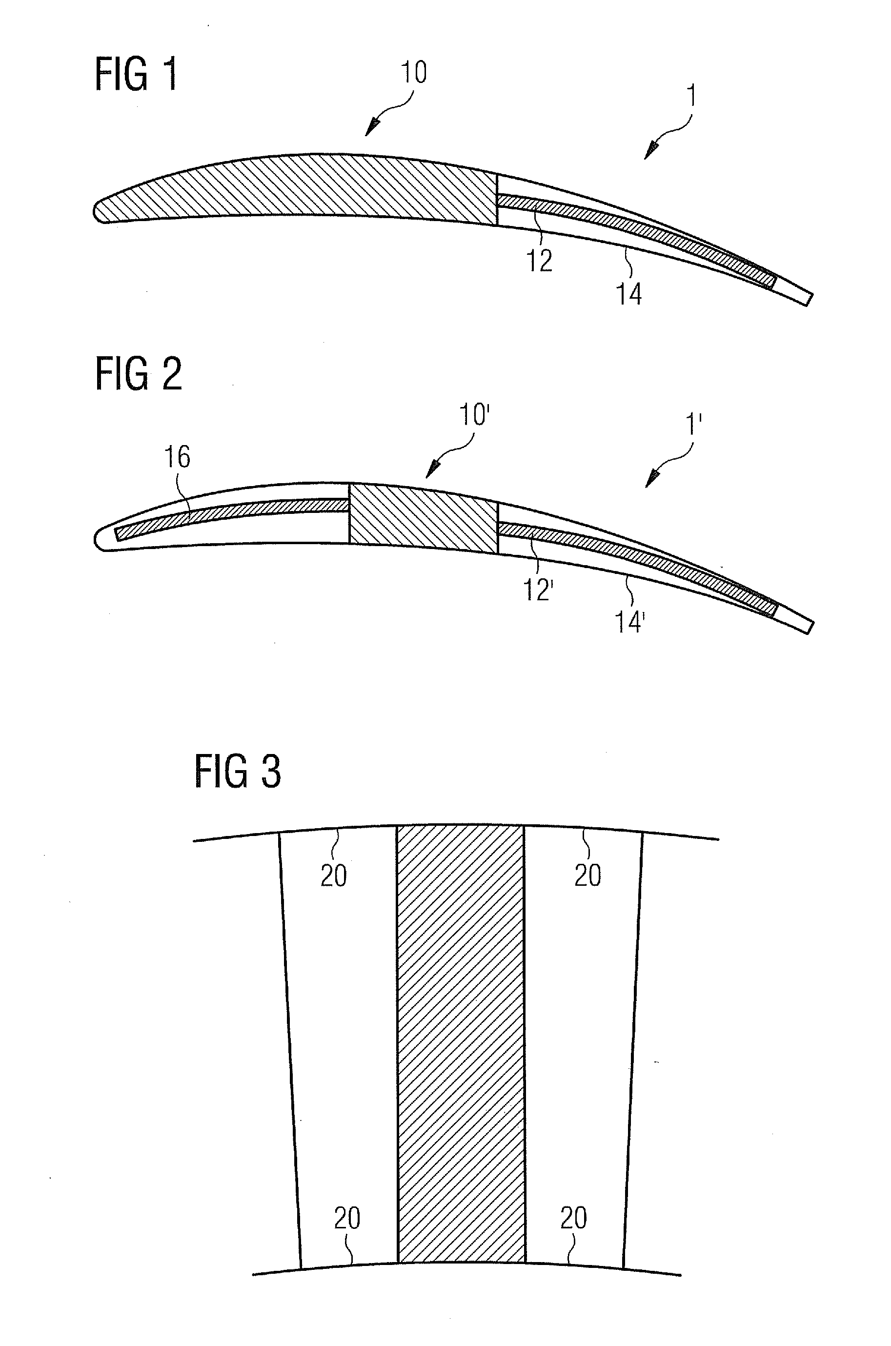
[0030] FIG. 1 shows a schematic longitudinal section of a first embodiment of the invention;
[0031] FIG. 2 shows a schematic longitudinal section of a second embodiment of the invention;
[0032] FIG. 3 shows a side view of the second embodiment, detailing the surface shaping of the vanes, and
[0033] FIG. 4 shows a schematic longitudinal section of a third embodiment of the invention;
[0034] FIG. 5 shows a schematic longitudinal section of a fourth embodiment of the invention:
DETAILED DESCRIPTION OF INVENTION
[0035] FIGS. 1 and 2 show a schematic longitudinal section of a first and a second embodiment of the invention, which may be used in a compressor, for instance in the compressor of a turbocharger.
[0036] Inlet vane 1 comprises a rigid, structurally fixed portion 10 which is coupled to an aft portion that comprises an electroactive polymer (EAP) member 12 and a flexible skin 14 of metal or polymer materials. In the present embodiment, EAP member 12 is laminated to skin 14, and is supplied with voltage using electrical leads (not shown). The electrical leads can be led through the structural fixed portion 10. Alternatively, the structural fixed portion 10 itself can be electrically conductive so as to replace one or more of the leads. If it replaces more than one lead it would comprise a respective number of conductive portions which are electrically isolated against each other.
[0037] As the person skilled in the art will acknowledge, in the entire description and claims, fore and aft relate to the upstream edge and downstream edge, or leading edge and trailing edge, respectively, the streaming direction being from left to right in the drawings, fore being displayed as left, aft being displayed as right.
[0038] Likewise, inlet vane 1' of the second embodiment, which is shown in FIG. 2, comprises a rigid, structurally fixed portion 10' which is coupled to an aft portion that comprises an EAP member 12' and a flexible skin 14' of metal or polymer materials. Also in this embodiment, EAP member 12' is laminated to skin 14', and is supplied with voltage using electrical leads. Like in the first embodiment, the leads can be led through the structural fixed portion, or the structural fixed portion can replace one or more leads.
[0039] However, in vane 1', a further, fore, portion is coupled to the structurally fixed portion 10'. In this portion, an EAP member 16 is laminated to a flexible skin as well. This EAP member 16 is also supplied with voltage by leads and/or the structural fixed member 10'
[0040] EAP layers 12, 12', and 16 comprise, or consist of, EAP materials and are designed such that a specified shape is taken at specific voltages that can be applied to the EAP layer. In the present case, particular degrees of deflection are associated to input voltage. Flexible skins 14 and 14' surround the EAP member to protect it against external influence and mechanical wear.
[0041] In embodiments, the skin 14, 14' does not have to be in direct contact with EAP member 12, 12' (EAP member 16 likewise) along the entire member length. If EAP member and skin are in direct contact only in defined portions, the relative displacement due to the curvatures and varying thickness of the vane when changing shape (i.e., bending) is being allowed for. Further, by having such a contact in defined portions of the EAP member, the force that the EAP member must provide in order to effect the bending of the vane is reduced. If, instead of one monolithic EAP member, a number of stripes, for instance up to 12 stripes, is mechanically coupled, such that they can slide relative to each other, the force or power required for a specified bending of the vane is further reduced.
[0042] FIG. 3 shows a side view of the plane of the vane according to the second embodiment. As can be seen, the edges of the vane are of spherical shape, so that leakage between a vane and the wall of a spherical compressor channel is minimized. Where indicated by 20, the shape-adapting portions of the vane are configured such that the spherical shape is kept while increasing vane stagger/camber.
[0043] FIGS. 4 and 5 shows a schematic longitudinal section of a third and a fourth embodiment of the invention, respectively, which may be used in a silencer of a turbocharger.
[0044] The configuration of these embodiments generally corresponds to the configuration of the embodiments described with respect to FIGS. 1 and 2. In particular, what has been said about supplying the EAPs with voltage with respect to the first and second embodiment is also true for the third and fourth embodiment.
[0045] In the silencer vane 3 shown in FIG. 4, a rigid portion 30 is located between and coupled to a fore portion that comprises an EAP layer 36 laminated to covering layer 34, and an aft portion, also comprising an EAP layer 32 laminated to covering layer 34.
[0046] Regarding the contact area between the EAP layers and covering layers of the third and fourth embodiment, the details given with regard to the first and second embodiment of the invention apply respectively.
[0047] In the silencer vane 3' shown in FIG. 5, the rigid portion 30' forms a voltage-invariant fore portion of the vane, and is coupled to an aft portion that is equivalent to the aft portion of vane 3.
[0048] In the vanes 3 and 3' of the third and fourth embodiments the materials of covering layers 34 and 34' are selected to both provide sound absorbing properties to the vane and to be flexible, so that, while the noise level is being reduced, the EAP member, upon changing its own shape, can influence the overall shape of the vane. Further, the structurally fixed parts 30 and 30' can be provided with sound-absorbing qualities by proper material selection.
[0049] Thus, the system presently shown provides an effective and reliable way of varying the vane shape in an electronic manner, and thus significantly enhances the reliability of operation and simplifies its practical application in turbochargers.
[0050] As the person skilled in the art will acknowledge, the inlet guide vane of the present invention and its embodiments is not limited to turbochargers. It may be applied in a profitable manner in various types of centrifugal compressors for compression of different gases, such as natural gas, oxygen, nitrogen, and the like. Further, it can be applied to axial compressors, in which case the first rows of variable guide vanes can be equipped with the technology of present invention, where the compressor operating temperature is within the range of the operating temperature of the EAP material.
* * * * *
D00000
D00001
D00002
XML
uspto.report is an independent third-party trademark research tool that is not affiliated, endorsed, or sponsored by the United States Patent and Trademark Office (USPTO) or any other governmental organization. The information provided by uspto.report is based on publicly available data at the time of writing and is intended for informational purposes only.
While we strive to provide accurate and up-to-date information, we do not guarantee the accuracy, completeness, reliability, or suitability of the information displayed on this site. The use of this site is at your own risk. Any reliance you place on such information is therefore strictly at your own risk.
All official trademark data, including owner information, should be verified by visiting the official USPTO website at www.uspto.gov. This site is not intended to replace professional legal advice and should not be used as a substitute for consulting with a legal professional who is knowledgeable about trademark law.