Air-Cushioning Material and Bag For Transporting Packaging Object
Taira; Toshiaki ; et al.
U.S. patent application number 12/087889 was filed with the patent office on 2010-12-30 for air-cushioning material and bag for transporting packaging object. This patent application is currently assigned to Japan Network Co., Ltd. Invention is credited to Hideaki Hashimoto, Toshiaki Taira.
| Application Number | 20100329589 12/087889 |
| Document ID | / |
| Family ID | 40506415 |
| Filed Date | 2010-12-30 |


| United States Patent Application | 20100329589 |
| Kind Code | A1 |
| Taira; Toshiaki ; et al. | December 30, 2010 |
Air-Cushioning Material and Bag For Transporting Packaging Object
Abstract
An air-cushioning material comprises a first air chamber that constitutes a bottom portion of a storage portion for storing a packaging object, and a second air chamber that constitutes a peripheral wall portion of the storage portion. The first air chamber comprises a valve capable of injecting and evacuating air, and an upper face portion in which a vent hole is formed, the first air chamber and the second air chamber are communicated each other via the vent hole. The second air chamber bulges into the storage portion, when the second air chamber is filled, via the vent hole, with air injected into the first air chamber via the valve. Thereby, sufficient air can fill the portion that constitutes the bottom portion of a storage portion where the packaging object is stored, and the cushioning effect of air can be effectively exerted, so that the packaging object can be effectively prevented from being damaged or the like on account of, for instance, external impacts.
| Inventors: | Taira; Toshiaki; (Saitama, JP) ; Hashimoto; Hideaki; (Chiba, JP) |
| Correspondence Address: |
    POSZ LAW GROUP, PLC
    12040 SOUTH LAKES DRIVE, SUITE 101
    RESTON
    VA
    20191
    US
|
| Assignee: | Japan Network Co., Ltd Saitama JP |
| Family ID: | 40506415 |
| Appl. No.: | 12/087889 |
| Filed: | February 29, 2008 |
| PCT Filed: | February 29, 2008 |
| PCT NO: | PCT/JP2008/053605 |
| 371 Date: | October 14, 2008 |
| Current U.S. Class: | 383/3 ; 206/521 |
| Current CPC Class: | B65D 81/052 20130101; B65D 81/03 20130101 |
| Class at Publication: | 383/3 ; 206/521 |
| International Class: | B65D 30/00 20060101 B65D030/00; B65D 81/02 20060101 B65D081/02 |
Claims
1. An air-cushioning material, comprising: a first air chamber that constitutes a bottom portion of a storage portion for storing a packaging object; and a second air chamber that constitutes a peripheral wall portion of the storage portion, wherein the first air chamber comprises a valve capable of injecting and evacuating air, and an upper face portion in which a vent hole is formed, the first air chamber and the second air chamber are communicated with each other via the vent hole, and the second air chamber bulges into the storage portion as the second air chamber is filled, via the vent hole, with air injected into the first air chamber via the valve.
2. The air-cushioning material according to claim 1, wherein the upper face portion of the first air chamber is supported by a support portion in the first air chamber so as to prevent the upper face portion of the first air chamber from bulging excessively into the storage portion.
3. The air-cushioning material according to claim 1, wherein an opening area of the vent hole of the upper face portion of the first air chamber is set in such a manner that air injected into the first air chamber via the valve flows into the second air chamber while filling up the first air chamber to such an extent that the packaging object stored in the storage portion can be supported.
4. The air-cushioning material according to claim 1, wherein the first air chamber has a substantially rectangular shape in a plan view, the valve is provided on one side face portion in a short side of the substantially rectangular shape in a plan view, and the vent hole is formed in the upper face portion, on a side of another side face portion opposing the one side face portion.
5. The air-cushioning material according to claim 1, wherein the support portion is a tubular member provided with at least one vent hole on a peripheral face thereof, and one end of the tubular member is bonded to the upper face portion and another end of the tubular member is bonded to a bottom face portion of the first air chamber.
6. The air-cushioning material according to claim 5, wherein an opening area of the vent hole of the tubular member is greater than an opening area of the vent hole of the upper face portion of the first air chamber.
7. The air-cushioning material according to claim 1, wherein a hard-elastic plate-like member is provided outside the bottom face portion of the first air chamber.
8. A bag for transporting a packaging object, comprising: the air-cushioning material according to claim 1; and a bag body capable of storing therein the air-cushioning material.
9. The bag for transporting a packaging object according to claim 8, wherein a hole is provided in the bag body in such a manner that the valve of the air-cushioning material can be exposed outside.
10. The bag for transporting a packaging object according to claim 9, wherein the bag body comprises a cover portion capable of covering the valve of the air-cushioning material.
11. The bag for transporting a packaging object according to claim 8, wherein mutually lockable locking members are provided in the air-cushioning material and the bag body.
Description
TECHNICAL FIELD
[0001] The present invention relates to an air-cushioning material capable of preventing damage or the like in a packaging object stored in a storage portion, and to a bag for transporting a packaging object using such an air-cushioning material.
BACKGROUND ART
[0002] Air-cushioning materials having an air chamber are widely used for packing and transporting packaging objects. In such air-cushioning materials, air is injected into an air chamber that is made to abut the entire surface or part of a packaging object, exploiting thereby the cushioning effect of the air in the air chamber to prevent the packaging object from being damaged on account of, for instance, external impacts.
[0003] Such conventional air-cushioning materials include, for instance, the air-cushioning material 200 proposed in Patent Document 1, comprising a first air chamber 201 that abuts a peripheral face portion and bottom portion of a packaging object 203, and a second air chamber 202, separate from the first air chamber 201, which abuts an upper face portion of the packaging object 203, as shown in FIG. 6.
Patent document 1: Japanese Patent Application Laid-open No. 2003-34363
DISCLOSURE OF THE INVENTION
Problem to be Solved by the Invention
[0004] The first air chamber 201 of the air-cushioning material 200 described in Patent Document 1 is made of a flexible material comprising, for instance, vinyl, rubber, a synthetic resin or the like. Accordingly, the air-cushioning material 200 is problematic in that although sufficient air fills the side face portions of the first air chamber 201 when air is injected into the first air chamber 201 where the packaging object 203 is stored, the bottom face portion of the first air chamber 201 fails to be sufficiently filled with air, depending on the weight of the packaging object 203. Such an air-cushioning material 200 is therefore problematic, as it fails to prevent effectively the packaging object 203 from being damaged or the like as a result of, for instance, external impacts.
[0005] With a view to filling the first air chamber 201 substantially uniformly with air, enough air can conceivably be injected so that the first air chamber 201 does not expand completely, followed by storing of the packaging object 203, after which air is injected again into the first air chamber 201. When the packaging object 203 is thus stored, however, the air in the bottom face portion of the first air chamber 201 may shift towards the side face portions, depending on the weight of the packaging object 203. Such a procedure is thus problematic in that the bottom face portion of the first air chamber 201 is not filled with sufficient air, and the packaging object 203 fails still to be effectively prevented from being damaged or the like as a result of, for instance, external impacts.
[0006] In the light of the above, it is an object of the present invention to provide an air-cushioning material, and a bag for transporting a packaging object using the air-cushioning material, in which sufficient air can fill the portions that constitute the bottom portion of a storage portion where the packaging object is stored, with less dependence on the weight of the packaging object, and in which the cushioning effect of air can be effectively exerted, so that the packaging object can be effectively prevented from being damaged or the like as a result of, for instance, external impacts.
Means for Solving the Problem
[0007] In order to solve the above problems, the present invention provides an air-cushioning material comprising a first air chamber that constitutes a bottom portion of a storage portion for storing a packaging object, and a second air chamber that constitutes a peripheral wall portion of the storage portion; wherein the first air chamber comprises a valve capable of injecting and evacuating air, and an upper face portion in which a vent hole is formed; the first air chamber and the second air chamber are communicated with each other via the vent hole; and the second air chamber bulges into the storage portion as the second air chamber is filled, via the vent hole, with air injected into the first air chamber via the valve (Invention 1).
[0008] According to the above invention (Invention 1), there are provided two air chambers, i.e. a first air chamber and a second air chamber, communicating with each other, so that air is injected first into the first air chamber that constitutes the bottom portion of the storage portion in which the packaging object is stored, and flows thereafter into the second air chamber. As a result, the packaging object can be supported by the air pressure of the first air chamber, while that same air can exert a sufficient cushioning effect. The packaging object can be effectively prevented thereby from being damaged or the like on account of, for instance, external impacts. Also, by providing just one valve capable of injecting and evacuating air into and from the first air chamber, the air-cushioning material according to the above invention (Invention 1) allows air to fill the first and second air chambers, so that air can be injected easily into the first and second air chambers. The air-cushioning material according to the above invention (Invention 1), furthermore, comprises a valve capable of injecting and evacuating air, and hence the storage space of the air-cushioning material can be shrunk after use by, for instance, evacuating the air and folding up the air-cushioning material, which can then be used again through renewed injection of air.
[0009] In the above invention (Invention 1), preferably, the upper face portion of the first air chamber is supported by a support portion in the first air chamber so as to prevent the upper face portion of the first air chamber from bulging excessively into the storage portion (Invention 2).
[0010] If the upper face portion of the first air chamber bulges excessively into the storage portion during injection of air into the first air chamber, the packaging object stored in the storage portion may jump out of the storage portion. According to the above invention (Invention 2), however, a support portion is provided in the first air chamber, whereby the upper face portion of the first air chamber can be prevented from bulging excessively, and the packaging object stored in the storage portion can be prevented from jumping out of the storage portion.
[0011] In the above inventions (Inventions 1, 2), preferably, the opening area of the vent hole of the upper face portion of the first air chamber is set in such a manner that air injected into the first air chamber via the valve flows into the second air chamber while filling up the first air chamber to such an extent that the packaging object stored in the storage portion can be supported (Invention 3).
[0012] According to the above invention (Invention 3), air injected into the first air chamber flows into the second air chamber while filling up the first air chamber to such an extent that the packaging object can be supported in the storage portion, whereby the packaging object stored in the storage portion is prevented from sagging into the first air chamber. The packaging object can be effectively prevented thereby from being damaged or the like on account of, for instance, external impacts.
[0013] In the above inventions (Inventions 1 to 3), preferably, the first air chamber has a substantially rectangular shape in a plan view; the valve is provided on one side face portion in a short side of the substantially rectangular shape in a plan view; and the vent hole is formed in the upper face portion, on the side of another side face portion opposing the one side face portion (Invention 4).
[0014] According to the above invention (Invention 4), a vent hole, as an air channel from the first air chamber to the second air chamber, is formed at a position removed from the valve through which air is injected into the first air chamber, and hence air can be injected into the second air chamber while spreading within the first air chamber. The packaging object can be effectively prevented thereby from being damaged or the like on account of, for instance, external impacts.
[0015] In the above inventions (Inventions 1 to 4), preferably, the support portion is a tubular member provided with at least one vent hole on the peripheral face thereof, one end of the tubular member is bonded to the upper face portion, and another end of the tubular member is bonded to the bottom face portion of the first air chamber (Invention 5).
[0016] According to the above invention (Invention 5), both ends of the support portion are respectively bonded to the upper face portion and the bottom face portion of the first air chamber, whereby the first air chamber can be prevented from bulging excessively into the storage portion when air is injected into the first air chamber. Also, a vent hole is formed on the peripheral face of the tubular member, and hence the tubular member can also be filled with air. The packaging object can be further effectively prevented thereby from being damaged or the like on account of, for instance, external impacts.
[0017] In the above invention (Invention 5), preferably, the opening area of the vent hole of the tubular member is greater than the opening area of the vent hole of the upper face portion of the first air chamber (Invention 6). According to such an invention (Invention 6), air fills first the interior of the tubular member, and then is injected into the second air chamber via the vent hole of the upper face portion of the first air chamber. As a result, air is injected into the second air chamber while spreading within the entire first air chamber. The packaging object on the bottom portion of the storage portion can be effectively prevented thereby from being damaged or the like on account of, for instance, external impacts.
[0018] In the above inventions (Inventions 1 to 6), preferably, a hard-elastic plate-like member is provided outside the bottom face portion of the first air chamber (Invention 7). According to such an invention (Invention 7), the bottom face portion of the first air chamber can be prevented from bulging out, preserving thus the substantially planar shape of the bottom face portion of the air-cushioning material. As a result, the air-cushioning material can be placed stably while air is being injected thereinto. Also, the first air chamber can be prevented thereby from being damaged on account of impacts from below the first air chamber.
[0019] When the above air-cushioning material is stored in a container such as a bag or the like for transporting a packaging object and used in that state, and a plate-like member is disposed on the bottom face portion of the bag, if air is injected into the first air chamber of the air-cushioning material, stored in the bag but not yet filled with air, the plate-like member may shift towards the side face portions of the air-cushioning material, or may push into the bottom face portion of the first air chamber, thereby deforming the first air chamber. According to the above invention (Invention 7), however, the plate-like member is provided outside the bottom face portion of the air-cushioning material, and hence the plate-like member is disposed between the bottom face portion of the bag and the bottom face portion of the air-cushioning material. This allows stabilizing the bottom face portion of the container for transporting a packaging object having stored therein the air-cushioning material.
[0020] Also, the present invention provides a bag for transporting a packaging object, comprising the air-cushioning material according to the above inventions (Inventions 1 to 7), and a bag body capable of storing therein the air-cushioning material (Invention 8).
[0021] The above invention (Invention 8) allows a packaging object to be transported while protected from external impacts or the like, thanks to the above air-cushioning material, so that the packaging object can be prevented from being damaged or the like during transport.
[0022] In the above invention (Invention 8), preferably, a hole is provided in the bag body in such a manner that the valve of the air-cushioning material can be exposed outside (Invention 9). Storing into the bag body an air-cushioning material that is expanded with injected air is troublesome, however, according to such an invention (Invention 9), the air-cushioning material can be stored in the bag body prior to injection of air into the air cushioning material, and air can be injected into the air-cushioning material in that state. The packaging object can be easily packed as a result.
[0023] In the above invention (Invention 9), preferably, the bag body comprises a cover portion capable of covering the valve of the air-cushioning material (Invention 10). According to such an invention (Invention 10), the valve is not exposed to the outside during transport, and hence the valve can thus be prevented from being damaged or the like on account of, for instance, external impacts. The cover portion, moreover, makes the bag design more attractive.
[0024] In the above inventions (Inventions 8 to 10), preferably, mutually lockable locking members are provided in the air-cushioning material and the bag body (Invention 11). According to such an invention (Invention 11), the air-cushioning material is firmly held in the bag body, so that the air-cushioning material does not shift inside the bag body during transport. The packaging object can be further effectively prevented thereby from being damaged or the like on account of, for instance, external impacts.
ADVANTAGEOUS EFFECT OF THE INVENTION
[0025] The present invention succeeds thus in providing an air-cushioning material, and a bag for transporting a packaging object using the air-cushioning material, in which sufficient air can fill the portions that constitute the bottom portion of a storage portion where the packaging object is stored, and in which the cushioning effect of air can be effectively exerted, so that the packaging object can be effectively prevented from being damaged or the like as a result of, for instance, external impacts.
BRIEF DESCRIPTION OF THE DRAWINGS
[0026] FIG. 1 is a perspective view showing an air-cushioning material according to an embodiment of the present invention.
[0027] FIG. 2 is an exploded perspective view showing the air-cushioning material according to an embodiment of the present invention.
[0028] FIG. 3 is a perspective view showing an air-cushioning material according to an embodiment of the present invention, viewed from a bottom face portion.
[0029] FIG. 4 is a perspective view showing a bag for transporting a packaging object using the air-cushioning material according to an embodiment of the present invention.
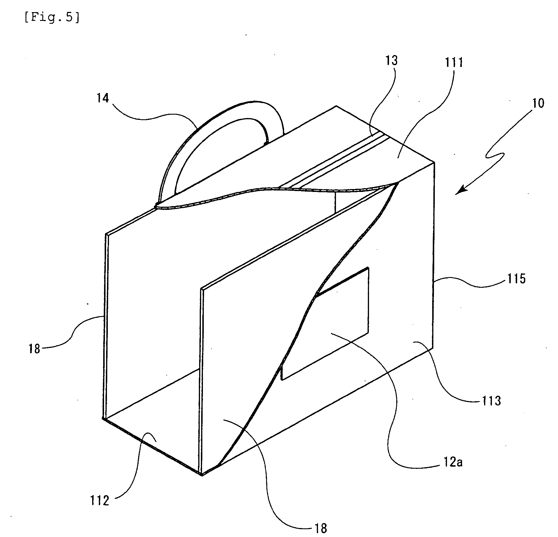
[0030] FIG. 5 is a partial cutaway perspective view showing the bag for transporting a packaging object in an embodiment of the present invention.
[0031] FIG. 6 is a perspective view showing a conventional air-cushioning material.
EXPLANATION OF REFERENCE NUMERALS
[0032] 1 . . . air-cushioning material [0033] 2 . . . first air chamber [0034] 21 . . . upper face portion [0035] 22 . . . bottom face portion [0036] 23 . . . first side face portion [0037] 24 . . . second side face portion [0038] 27 . . . vent hole [0039] 28 . . . support portion [0040] 283 . . . peripheral face portion [0041] 284 . . . vent hole [0042] 29 . . . bottom plate (plate-like member) [0043] 3 . . . second air chamber [0044] 34 . . . hook-and-loop fastener (locking member) [0045] 4 . . . storage portion [0046] 5 . . . valve [0047] 6 . . . packaging object [0048] 10 . . . bag for transporting a packaging object [0049] 11 . . . bag body [0050] 15 . . . hole [0051] 16 . . . cover portion
BEST MODE FOR CARRYING OUT THE INVENTION
[0052] The air-cushioning material according to an embodiment of the present invention and the bag for transporting a packaging object using the same are explained next with reference to accompanying drawings. FIG. 1 is a perspective view showing the air-cushioning material according to the present embodiment; FIG. 2 is an exploded perspective view showing the air-cushioning material according to the embodiment; FIG. 3 is a perspective view showing the air-cushioning material according to the embodiment, as viewed from a bottom face portion; FIG. 4 is a perspective view showing a bag for transporting a packaging object using the air-cushioning material according to the embodiment; and FIG. 5 is a partial cutaway perspective view showing the bag for transporting a packaging object in the embodiment.
[0053] As shown in FIG. 1, an air-cushioning material 1 according to the present embodiment comprises a first air chamber 2 that constitutes the bottom portion of a storage portion 4 in which a packaging object 6 is stored, and a second air chamber 3 that constitutes the peripheral wall portion of the storage portion 4.
[0054] As shown in FIG. 2, the first air chamber 2 is formed by bonding together a top face portion 21, a bottom face portion 22 and first to fourth side face portions 23 to 26, obtained by forming a resin sheet or the like to a substantially rectangular shape, in such a manner that the first air chamber 2 becomes a substantially rectangular parallelepiped shape (substantially rectangular shape in plan view).
[0055] The material of the first air chamber 2 is not particularly limited, provided that it has a certain flexibility. In terms of strength, for instance, there is preferably used a resin sheet or the like comprising polyurethane. When the material comprised in the first air chamber 2 is a heat-sealable material, the first air chamber 2 can be easily produced by heat-sealing the top face portion 21, the bottom face portion 22 and the first to fourth side face portions 23 to 26 in such a manner that the first air chamber 2 becomes a substantially rectangular parallelepiped shape (substantially rectangular shape in plan view). The top face portion 21, the bottom face portion 22 and the first to fourth side face portions 23 to 26 may also respectively be adhered by adhesive.
[0056] The first air chamber 2 is not limited to being formed as described above. The first air chamber 2 may be formed, for instance, through blow molding of a resin or the like, or by folding a flat unfolded resin sheet or the like comprising the top face portion 21, the bottom face portion 22 and the first to fourth side face portions 23 to 26, and bonding then together the sides that come into contact.
[0057] A valve 5, for injecting air into the first air chamber 2 and evacuating air from the first air chamber 2, is provided at substantially the central portion of the first side face portion 23 in one of the short sides of the plan-view substantially rectangular shape of the first air chamber 2.
[0058] The valve 5 has a substantially L-shaped tube portion and an opening/closing valve provided at one end of the tube portion. Air can be injected into the first air chamber 2, and can be evacuated from the first air chamber 2, by opening the opening/closing valve. The interior of the first air chamber 2 and the second air chamber 3 (air-cushioning material 1) can be sealed, and air can be prevented from leaking out of the air-cushioning material 1, by closing the opening/closing valve.
[0059] One vent hole 27 is formed on the top face portion 21 of the first air chamber 2. The vent hole 27 is formed at substantially the central portion of the end of the top face portion 21 on the side of the second side face portion 24 that opposes the first side face portion 23, where the valve 5 is provided. The first air chamber 2 and the second air chamber 3 communicate via the vent hole 27.
[0060] The opening area of the vent hole 27 of the top face portion 21 of the first air chamber 2 may be set in such a manner that the air injected into the first air chamber 2, via the valve 5, flows into the second air chamber while filling the first air chamber 2 to such an extent that the packaging object 6 can be supported in the storage portion 4. For instance, the opening area of the valve 5 may be appropriately set so as to be smaller than the opening area of the vent hole 27. When for instance the openings of the vent hole 27 and the valve 5 are circular, the opening diameter of the vent hole 27 may be set to be smaller than the opening diameter of the valve 5.
[0061] As shown in FIG. 3, pockets 221, 221 having openings are provided at both outer ends of the bottom face portion 22 of the first air chamber 2 in such a manner that the openings of the pockets 221, 221 oppose each other. The pocket 221 is obtained by bonding together three sides of a substantially rectangular resin sheet with the short side, and part of the long sides adjacent to the short side, of the bottom face portion 22. A bottom plate 29 is provided outside the bottom face portion 22 of the first air chamber 2, in such a manner that both ends of the bottom plate 29, in the longitudinal direction, are respectively inserted into the openings of the pockets 221, 221. As the bottom plate 29 there can be used, for instance, a plastic plate, cardboard or the like.
[0062] As shown in FIG. 2, a support portion 28 comprising a tubular member of substantially rectangular shape in plan view is provided in the first air chamber 2, such that an upper end 281 of the support portion 28 is bonded to the top face portion 21 of the first air chamber 2, and a lower end 282 of the support portion 28 is bonded to the bottom face portion 22 of the first air chamber 2. The upper end 281 and the lower end 282 of the support portion 28 may be respectively bonded to the top face portion 21 and the bottom face portion 22 by heat-sealing, or by adhesive or the like.
[0063] When the support portion 28 is shaped as, for instance, four bands or strings, attaching the support portion 28 in the first air chamber 2 requires eight bonding operations, which may complicate the production of the air-cushioning material 1. However, using a tubular member as the support portion 28 allows easily attaching the support portion 28 in the first air chamber 2 by way of just two bonding operations.
[0064] The surface area of the plan-view substantially rectangular shape of the support portion 28 (opening area of the tubular member) is set to be slightly smaller than the surface area of the bottom portion of the storage portion 4. This allows preventing the packaging object 6, stored in the storage portion 4, from sagging (downwards) into the first air chamber 2.
[0065] Two vent holes 284, 284 are formed, opposite each other, on the peripheral face portion 283 of the support portion 28, such that air flows into the support portion 28 via the vent holes 284, 284. The number of vent holes 284 formed on the peripheral face portion 283 is not particularly limited, provided that the strength of the support portion 28 can be preserved to certain degree, and thus there may be formed three or more vent holes 284.
[0066] The total opening area of the vent holes 284 formed on the peripheral face portion 283 of the support portion 28 is preferably larger than the opening area of the vent hole 27 formed on the top face portion 21. The air injected into the first air chamber 2 flows thereby more easily into the support portion 28 before flowing into the second air chamber 3, and the first air chamber 2 can be filled with enough air so that the packaging object 6 stored in the storage portion 4 can be supported.
[0067] The material used in the support portion 28 is not particularly limited, and may be, for instance, the same material used as in the first air chamber 2.
[0068] The second air chamber 3 comprises an inner wall portion 31 that constitutes a peripheral wall portion of the storage portion 4, an outer wall portion 32 provided outside the inner wall portion 31 so as to leave a gap with the inner wall portion 31, and a lid portion 33 that covers the gap between the inner wall portion 31 and the outer wall portion 32. The second air chamber 3 has substantially a rectangular ring shape in a plan view.
[0069] The inner wall portion 31 and the outer wall portion 32 of the second air chamber 3 are configured as a tubular portion having substantially a rectangular shape in a plan view, and are obtained by bonding four sheet-like members, from a resin sheet or the like formed to a substantially rectangular shape, or by folding, and then bonding, one sheet-like member from a resin sheet or the like formed to a substantially rectangular shape. The inner wall portion 31 and the outer wall portion 32 may each be formed through heat-sealing of sheet-like members, or through bonding of sheet-like members by adhesive or the like. The material used in the second air chamber 3 may be the same material as that of the first air chamber 2.
[0070] The lid portion 33 has a substantially rectangular ring shape, such that an inner edge 331 of the lid portion 33 is bonded to an upper end 311 of the inner wall portion 31, and an outer edge 332 of the lid portion 33 is bonded to an upper end 321 of the outer wall portion 32. The lid portion 33 may be bonded the inner wall portion 31 and the outer wall portion 32 by heat-sealing or by adhesive or the like.
[0071] A lower end 312 of the inner wall portion 31 of the second air chamber 3 is bonded to the top face portion 21 of the first air chamber 2. A lower end 322 of the outer wall portion 32 of the second air chamber 3 is bonded to the four sides of the top face portion 21 of the first air chamber 2. As a result there forms the second air chamber 3, having a substantially rectangular ring shape in a plan view, and there forms, in the second air chamber 3, the storage portion 4 for storing the packaging object 6.
[0072] Hook-and-loop fasteners 34, 34 are attached, opposite each other, to the outer top portion of the outer wall portion 32 (outer wall portion 32 constituting the long side of the substantially rectangular shape in a plan view) of the second air chamber 3, so as to extend along the longitudinal direction of the outer wall portion 32. As a result, when the air-cushioning material 1 is stored in a transport container (for instance, the below-described bag for transporting a packaging object), the air-cushioning material 1 and the transport container can lock with each other, and the air-cushioning material 1 can be easily fixed in the transport container by providing hook-and-loop fasteners (not shown) capable of catching with the hook-and-loop fasteners 34, 34, on the inner face of the transport container. When the packaging object 6 is stored in the storage portion 4, the storage opening of the storage portion 4 of the air-cushioning material 1 is widened through mutual locking of the hook-and-loop fasteners 34, 34 with the lockable hook-and-loop fasteners. This has the effect of facilitating storage of the packaging object 6 in the storage portion 4.
[0073] By being stored in a bag for transporting a packaging object 10 such as the one shown in FIG. 4, the air-cushioning material 1 according to the above-described present embodiment can be used as an air-cushioning material for transporting a packaging object.
[0074] As shown in FIG. 4, the bag for transporting a packaging object 10 comprises a bag body 11 of substantially rectangular parallelepiped shape having a top face portion 111, a bottom face portion 112, a front side face portion 113, a rear side face portion 114, a right side face portion 115 and a left side face portion 116; storage pockets 12a, 12b provided respectively on substantially the center of the front side face portion 113 and the rear side face portion 114 of the bag body 11; a fastener 13 provided on the top face portion 111 of the bag body 11; and handles 14, 14 provided respectively on the front side face portion 113 and the rear side face portion 114 of the bag body 11.
[0075] The top face portion 111, bottom face portion 112, front side face portion 113, rear side face portion 114, right side face portion 115 and left side face portion 116 of the bag body 11 comprise each a flexible material. Examples of such a material include, but not limited to, cloth materials such as woven cloth of synthetic fibers, canvas or the like, leather materials such as natural leather, artificial leather or the like, or vinyl materials and the like.
[0076] The size of the bag body 11 is such so as to allow the air-cushioning material 1 to be tightly stored in the bag body 11. The air-cushioning material 1 is prevented thereby from bulging out excessively when air is injected into the air-cushioning material 1, while allowing the air-cushioning material 1 to expand outwards somewhat. The air-cushioning material 1 becomes thereby firmly held in the bag body 11, and as a result the air-cushioning material 1 can be prevented from shifting in the bag body 11 during transport of the packaging object.
[0077] A hole 15, through which the valve 5 of the air-cushioning material 1 stored in the bag body 11 can be exposed to the outside, is formed at substantially the center of the lower portion of the left side face portion 116 of the bag body 11. Below the hole 15 there is attached an end of a cover portion 16 that can cover the valve 5 exposed through the hole 15. A hook-and-loop fastener 172 is attached above the hole 15.
[0078] A hook-and-loop fastener 171 is attached on the surface of the other end of the cover portion 16, on the side of the left side face portion 116. Thus, the hook-and-loop fastener 172 and the hook-and-loop fastener 171 attached above the hole 15 of the left side face portion 116 can fasten with each other when the valve 5, exposed through the hole 15 of the left side face portion 116, is covered by the cover portion 16.
[0079] The fastener 13 is provided so as to extend continuously in the longitudinal direction of the top face portion 111, from the upper portion of the left side face portion 116 of the bag body 11 up to the upper portion of the right side face portion 115 of the bag body 11. The top face portion 111, the upper portion of the right side face portion 115 and the upper portion of the left side face portion 116 of the bag body 11 can be opened and closed by opening and closing the fastener 13. When the fastener 13 is opened, an opening can form in the bag body 11 such that the air-cushioning material 1 can be stored in the bag body 11 via the opening.
[0080] As shown in FIG. 5, on the inner faces of the front side face portion 113 and the rear side face portion 114 of the bag body 11 there are respectively provided hard-elastic plate-like members 18, 18 having substantially the same size, or being slightly smaller than, the front side face portion 113 (rear side face portion 114). The air-cushioning material 1 (bag body 11) is prevented thereby from expanding excessively at the front side face portion 113 and the rear side face portion 114 when air is injected into the air-cushioning material 1. Also, external forces derived from outside impacts onto the front side face portion 113 and/or the rear side face portion 114 are dispersed over the surface of the plate-like members 18, thereby preventing impacts on the air-cushioning material 1 from concentrating at one point. The packaging object 6 can be held and protected, as a result, with a substantially uniform air pressure at all times.
[0081] The front side face portion 113 and the rear side face portion 114 are supported on the plate-like members 18, 18, and hence, in case of an impact on the top face portion 111, the right side face portion 115 or the left side face portion 116 of the bag body 11, the bag body 11 caves inward only by the length of the top face portion 111, the right side face portion 115 or the left side face portion 116, in the transversal direction. Therefore, outside impacts on the top face portion 111, the right side face portion 115 and the left side face portion 116 are less likely to reach the packaging object 6, and thus the packaging object 6 can be effectively prevented from being damaged and the like.
[0082] Moreover, the shape of the bag for transporting a packaging object 10 can be preserved by supporting the front side face portion 113 and the rear side face portion 114 on the plate-like members 18, 18. The same material of the bottom plate 29 can be used in the plate-like members 18.
[0083] The storage pockets 12a, 12b are respectively attached on substantially the center of the front side face portion 113 and of the rear side face portion 114 of the bag body 11. The storage pockets 12a, 12b are substantially rectangular and have a size that allows placing therein a label or the like indicating the type of packaging object 6, or a tag with a shipping address for package delivery or the like. Except the upper side, three sides of the storage pockets 12a, 12b among the four sides thereof are attached to the front side face portion 113 and the rear side face portion 114 of the bag body 11.
[0084] Attaching thus two storage pockets 12a, 12b allows placing a tag in one storage pocket 12a and a label indicating the type of packaging object 6 in the other storage pocket 12b. Doing so allows easily identifying the type of packaging object 6 without opening the bag for transporting a packaging object 10.
[0085] A pair of handles 14, 14 is sewn onto the respective upper portions of the front side face portion 113 and the rear side face portion 114 of the bag body 11. The bag for transporting a packaging object 10 can be hand-carried more handily as a result.
[0086] Hook-and-loop fasteners (not shown), capable of locking with the hook-and-loop fasteners 34 attached to the outer wall portion 32 of the second air chamber 3 of the air-cushioning material 1, are respectively attached at the inward upper portion of the front side face portion 113 and the inward upper portion of the rear side face portion 114 of the bag body 11.
[0087] In the air-cushioning material 1 and the bag for transporting a packaging object 10 having the above constitutions, the air-cushioning material 1 is stored in the bag body 11 of the bag for transporting a packaging object 10, the packaging object 6 is stored in the storage portion 4, and air is injected into the first air chamber 2, via the valve 5, when the opening/closing valve of the valve 5 is open.
[0088] The vent hole 27 formed on the top face portion 21 of the first air chamber 2 is set in such a manner that air injected into the first air chamber 2 flows into the second air chamber 3 while filling up the first air chamber 2 to such an extent that the packaging object 6 can be supported. Therefore, when air is injected via the valve 5, with the packaging object 6 stored in the storage portion 4, air flows into the second air chamber 3 while spreading within the first air chamber 2.
[0089] Thereupon, air becomes injected also into the support portion 28, via the vent holes 284, 284 formed on the peripheral face portion 283 of the support portion 28 provided in the first air chamber 2. The packaging object 6 becomes supported as a result by the first air chamber 2 into which air is injected.
[0090] Herein, the upper end 281 and the lower end 282 of the support portion 28 are respectively bonded to the top face portion 21 and the bottom face portion 22 of the first air chamber 2, and hence air can be injected into the first air chamber 2 without the top face portion 21 bulging excessively into the storage portion 4. The packaging object 6 stored in the storage portion 4 is prevented thereby from jumping out of the storage portion 4.
[0091] Thereafter, continued injection of air via the valve 5 causes air to flow into the second air chamber 3, via the vent hole 27 formed on the top face portion 21, while the first air chamber 2 is kept filled with enough air so that the packaging object 6 stored in the storage portion 4 can be supported. As air flows into the second air chamber 3, the inner wall portion 31 of the second air chamber 3 bulges into the storage portion 4, allowing thereby the packaging object 6 to be firmly held while preventing the packaging object from shifting or collapsing.
[0092] When the height of the packaging object 6 is smaller than that of the storage portion 4, the portion that is not in contact with the packaging object 6, in the inner wall portion 31 of the second air chamber 3 that constitutes the peripheral wall portion of the storage portion 4, bulges into of the storage portion 4. The air in the bulging part exerts as a result a cushioning effect on the upper face portion of the packaging object 6, so that the packaging object 6 can be protected, over the entire surface thereof, from outer impacts or the like.
[0093] Once enough air is injected into the first air chamber 2 and the second air chamber 3 so as to allow firmly holding the packaging object 6, air injection is discontinued and the opening/closing valve of the valve 5 is closed. As a result, the packaging object 6 can be firmly held in the storage portion 4, without air leaking out of the first air chamber 2 or the second air chamber 3. At the same time, the cushioning effect of the air that fills the first air chamber 2 and the second air chamber 3 allows preventing the packaging object 6 from being damaged or the like on account of, for instance, external impacts.
[0094] Lastly, the fastener 13 of the bag body 11 is fastened. The packaging object 6 can be packaged as a result in a convenient way for hand carrying, while firmly held by the air-cushioning material 1. The packaging object 6 can be thus prevented from being damaged on account of, for instance, external impacts, and from shifting or collapsing in the storage portion 4, during transport.
[0095] In the above explanation, air is injected first into the first air chamber 2 of the air-cushioning material 1 according to the present embodiment, with air flowing thereafter into the second air chamber 3. This allows, as a result, sufficient air to fill the first air chamber 2, whereupon the packaging object 6 can be supported by the air pressure of the first air chamber 2, and allows the cushioning effect of the air to be sufficiently brought out. The packaging object 6 can be thus effectively prevented from being damaged or the like on account of, for instance, external impacts.
[0096] Also, the bag for transporting a packaging object 10 having such an air-cushioning material 1 stored therein allows transporting the packaging object 6 while protected from external impacts or the like, and allows effectively preventing the packaging object 6 from being damaged or the like during transport.
[0097] The above embodiment has been described for facilitating understanding of the present invention, and not for limiting the present invention. The various elements described in the above embodiment are thus deemed to also include all design modifications and equivalents falling under the technical scope of the present invention.
[0098] In the above embodiment, for instance, one vent hole 27 is formed in the top face portion 21 of the first air chamber 2 at a position removed from the valve 5. However, there may be formed two or more vent holes, at any position in the in the top face portion 21, provided that the air injected into the first air chamber flows into the second air chamber while filling up the first air chamber to such an extent that the packaging object stored in the storage portion can be supported.
[0099] In the above embodiment, the support portion 28 comprises a tubular member. However, the support portion 28 is not particularly limited thereto, and may comprise, for instance plural band-like members or the like, provided that the top face portion 21 of the first air chamber 2 can be prevented from bulging excessively into the storage portion.
[0100] In the above embodiment, the air-cushioning material 1 has a substantially rectangular shape in a plan view (substantially rectangular parallelepiped shape), but the air-cushioning material 1 may be appropriately deformed corresponding to the outer shape of the packaging object 6, and may hence have an oval shape, circular shape, square shape or the like in a plan view. In this case, the bag for transporting a packaging object 10 is preferably shaped corresponding to the shape of the air-cushioning material 1.
[0101] In the above embodiment, a protective sheet comprising nylon or the like may also be provided on the inner wall portion 31 of the second air chamber 3, and on the top face portion 21 of the first air chamber 2, on the side of the storage portion 4. The first air chamber 2 and/or the second air chamber 3 become thereby less likely to be punctured, damaged or the like when packing a packaging object 6 having protrusions.
[0102] In the above embodiment, the air-cushioning material 1 is stored in the bag for transporting a packaging object 10 and used in that state. The state of the air-cushioning material 1, however, is not limited thereto, and may also be stored in, for instance, a box such as a cardboard box, a container or the like, and used.
EXAMPLES
[0103] Following is a more detailed description of the present invention through examples; however, the scope of the present invention is not limited by these examples.
[0104] Polyurethane resin sheets having a thickness of 0.3 mm (by Nihon Matai Co., Ltd.) were prepared, the first air chamber 2, the second air chamber 3 and the support portion 28 were produced by heat-sealing there sheets, and an L-shaped valve 5 was attached to the first side face portion 23 of the first air chamber 2. Thereby, the air-cushioning material 1 shown in FIG. 1 was produced.
[0105] The sizes of the first air chamber 2, the second air chamber 3 and the support portion 28 were set as follows.
First air chamber 2 . . . height: 90 mm, longitudinal-direction length 420 mm, short-side-direction length: 180 mm Opening diameter (opening area) of the vent hole 27 of the top face portion 21 . . . 8 mm (16 .pi. mm.sup.2) Second air chamber 3 . . . height: 210 mm, width between the inner wall portion 31 and the outer wall portion 32: 40 mm Support portion 28 . . . height: 90 mm, longitudinal-direction length 320 mm, short-side-direction length: 80 mm Opening diameter (opening area) of the vent holes 284 of the support portion 28 . . . 8 mm (16 .pi. mm.sup.2) Opening diameter (opening area) of the L-shaped valve 5 . . . 10 mm (25 .pi. mm.sup.2)
[0106] A ceramic cup weighing 380g and a glass vase weighing 1560g were respectively stored, as packaging objects 6, in the storage portion 4 of the above air-cushioning material 1, and then air was injected through the L-shaped valve 5. Thereupon, air flowed firstly into the first air chamber 2, expanding the first air chamber 2 enough so that the packaging objects 6 were successfully supported by the air that had flowed into the first air chamber 2. The second air chamber 3 expands then into the storage portion 4, thereby causing the packaging object 6 to be firmly held in the storage portion 4. With the cup or the vase stored in the storage portion 4, the air-cushioning material 1 was dropped from a height of 1.7 m, whereupon neither the cup nor the vase were damaged. The air-cushioning material 1 according to the present example proved thus to have an excellent cushioning effect on the packaging object 6.
INDUSTRIAL APPLICABILITY
[0107] The air-cushioning material and the bag for transporting a packaging object using the air-cushioning material can be appropriately used, for instance, in package delivery, transport of parts between factories and other applications.
* * * * *
D00000
D00001
D00002
D00003
D00004
D00005
D00006
XML
uspto.report is an independent third-party trademark research tool that is not affiliated, endorsed, or sponsored by the United States Patent and Trademark Office (USPTO) or any other governmental organization. The information provided by uspto.report is based on publicly available data at the time of writing and is intended for informational purposes only.
While we strive to provide accurate and up-to-date information, we do not guarantee the accuracy, completeness, reliability, or suitability of the information displayed on this site. The use of this site is at your own risk. Any reliance you place on such information is therefore strictly at your own risk.
All official trademark data, including owner information, should be verified by visiting the official USPTO website at www.uspto.gov. This site is not intended to replace professional legal advice and should not be used as a substitute for consulting with a legal professional who is knowledgeable about trademark law.