Image Processing Apparatus and Associated Method
Chen; Mei-Ju ; et al.
U.S. patent application number 12/783699 was filed with the patent office on 2010-12-30 for image processing apparatus and associated method. This patent application is currently assigned to MSTAR SEMICONDUCTOR, INC.. Invention is credited to Mei-Ju Chen, Jen-Shi Wu.
| Application Number | 20100329356 12/783699 |
| Document ID | / |
| Family ID | 43380715 |
| Filed Date | 2010-12-30 |


| United States Patent Application | 20100329356 |
| Kind Code | A1 |
| Chen; Mei-Ju ; et al. | December 30, 2010 |
Image Processing Apparatus and Associated Method
Abstract
An image processing apparatus includes an image decoding unit and an image adjusting unit. The image decoding unit decodes a data stream to generate a first image and a second image respectively having a first pixel and a second pixel at the same target position. The image adjusting unit generates a luminance motion parameter and a chrominance motion parameter according to initial luminance values and initial chrominance values of the first pixel and the second pixel, and generates an adjusted chrominance value of the first pixel by weighted averaging the initial chrominance values of the first pixel according to the luminance motion parameter and the chrominance motion parameter.
| Inventors: | Chen; Mei-Ju; (Hsinchu Hsien, TW) ; Wu; Jen-Shi; (Hsinchu Hsien, TW) |
| Correspondence Address: |
    EDELL, SHAPIRO & FINNAN, LLC
    1901 RESEARCH BOULEVARD, SUITE 400
    ROCKVILLE
    MD
    20850
    US
|
| Assignee: | MSTAR SEMICONDUCTOR, INC. Hsinchu Hsien TW |
| Family ID: | 43380715 |
| Appl. No.: | 12/783699 |
| Filed: | May 20, 2010 |
| Current U.S. Class: | 375/240.25 ; 348/663; 348/E9.035; 375/E7.026 |
| Current CPC Class: | H04N 9/78 20130101; H04N 9/646 20130101 |
| Class at Publication: | 375/240.25 ; 348/663; 375/E07.026; 348/E09.035 |
| International Class: | H04N 9/77 20060101 H04N009/77; H04N 7/12 20060101 H04N007/12 |
Foreign Application Data
| Date | Code | Application Number |
|---|---|---|
| Jun 26, 2009 | TW | 098121607 |
Claims
1. An image processing apparatus, comprising: an image decoding unit, for decoding a data stream to generate at least a first image and a second image, the first image and the second image respectively having a first pixel and a second pixel at the same position; and an image adjusting unit, coupled to the image decoding unit, comprising: a luminance motion calculating module, for calculating a luminance motion parameter according to an initial luminance value of the first pixel and an initial luminance value of the second pixel; a chrominance motion calculating module, for calculating a chrominance motion parameter according to an initial chrominance value of the first pixel and an initial chrominance value of the second pixel; and a chrominance adjusting module, for generating an adjusted chrominance value of the first pixel according to a weighted average of the initial chrominance value of the first pixel and the initial chrominance value of the second pixel with reference to the luminance motion parameter and the chrominance motion parameter.
2. The image processing apparatus as claimed in claim 1, wherein the luminance motion calculating module calculates the luminance motion parameter further according to a plurality of initial luminance values of pixels neighboring to the first pixel and a plurality of initial luminance values of pixels neighboring to the second pixel.
3. The image processing apparatus as claimed in claim 2, wherein the chrominance motion calculating module further calculates the chrominance motion parameter according to a plurality of initial chrominance values of pixels neighboring to the first pixel and a plurality of initial chrominance values of pixels neighboring to the second pixel.
4. The image processing apparatus as claimed in claim 1, wherein the first image and the second image are fields or frames, the first image is a current image, and the second image is a previous image or a next image.
5. The image processing apparatus as claimed in claim 1, wherein the chrominance motion calculating module comprises a chrominance motion parameter adjusting module, for generating a cross-color edge value according to the initial chrominance value of the first pixel and the initial chrominance values of pixels neighboring to the first pixel; generating a real-color edge value according to the initial chrominance value of the first pixel, the initial chrominance values of pixels neighboring to the first pixel, the initial chrominance value of the second pixel, and the initial chrominance values of pixels neighboring to the second pixel; and generating an adjusted chrominance motion parameter according to the chrominance motion parameter, the cross-color edge value and the real-color edge value to replace the chrominance motion parameter.
6. The image processing apparatus as claimed in claim 5, wherein the chrominance motion parameter adjusting module generates the cross-color edge value by calculating differences between the initial chrominance value of the first pixel and the initial chrominance values of pixels neighboring to the first pixel.
7. The image processing apparatus as claimed in claim 5, wherein the chrominance motion parameter adjusting module generates the real-color edge value by weighted averaging a plurality of differences of a plurality of average chrominance values of the first pixel and pixels neighboring to the first pixel, wherein the average chrominance values are the averages of the initial chrominance values of the first pixel and the second pixel and the pixels neighboring to the first pixel and the second pixel.
8. The image processing apparatus as claimed in claim 1, wherein the chrominance adjusting module further generates a motion parameter according to the luminance motion parameter and the chrominance motion parameter, determines two weights for the first pixel and the second pixel according to the motion parameter, and generates the adjusted chrominance value of the first pixel by weighted averaging the initial chrominance values of the first pixel and the second pixel, wherein the motion parameter being positively correlated with the initial chrominance value of the first pixel.
9. An image processing apparatus, for processing a plurality of images comprising a first image and a second image, the first image and the second image respectively having a first pixel and a second pixel at the same target position, the image processing apparatus comprising: a chrominance averaging module, for averaging two initial chrominance values of the first pixel and the second pixel to generate an average chrominance value of the first pixel; a luminance motion parameter calculating module, for calculating a luminance motion parameter according to two initial luminance values of the first pixel and the second pixel; a chrominance motion calculating module, for calculating a chrominance motion parameter according to the initial chrominance values of the first pixel and the second pixel; and a chrominance adjusting module, for generating an adjusted chrominance value of the first pixel by weighted averaging the average chrominance value of the first pixel and the initial chrominance value of the first pixel according to the luminance motion parameter and the chrominance motion parameter.
10. The image processing apparatus as claimed in claim 9, wherein the luminance motion calculating module calculates the luminance motion parameter further according to a plurality of initial luminance values of pixels neighboring to the first pixel and the second pixel.
11. The image processing apparatus as claimed in claim 10, wherein the chrominance motion calculating module calculates the chrominance motion parameter further according to a plurality of initial chrominance values of pixels neighboring to the first pixel and the second pixel.
12. The image processing apparatus as claimed in claims 9, wherein the chrominance motion calculating module comprises a chrominance motion parameter adjusting module, for generating a cross-color edge value according to the initial chrominance value of the first pixel and the initial chrominance values of pixels neighboring to the first pixel; generating a real-color edge value according to the initial chrominance value of the first pixel, the initial chrominance values of pixels neighboring to the first pixel, the initial chrominance value of the second pixel, and the initial chrominance values of pixels neighboring to the second pixel; and generating an adjusted chrominance motion parameter according to the chrominance motion parameter, the cross-color edge value and the real-color edge value to replace the chrominance motion parameter.
13. An image processing method, comprising: decoding a data stream to generate a plurality of images comprising a first image and a second image, the first image and the second image respectively having a first pixel and a second pixel at the same target position; calculating a luminance motion parameter according to an initial luminance value of the first pixel and an initial luminance value of the second pixel; calculating a chrominance motion parameter according to a chrominance value of the first pixel and a chrominance value of the second pixel; and generating an adjusted chrominance value of the first pixel by weighted averaging the initial chrominance value of the first pixel and the initial chrominance value of the second pixel according to the luminance motion parameter and the chrominance motion parameter.
14. The image processing method as claimed in claim 13, wherein the step of calculating the luminance motion parameter further comprises calculating the luminance motion parameter according to a plurality of initial luminance values of pixels neighboring to the first pixel and the second pixel.
15. The image processing method as claimed in claim 14, wherein the step of calculating the chrominance motion parameter further comprises calculating the chrominance motion parameter according to a plurality of initial chrominance values of pixels neighboring to the first pixel and the second pixel.
16. The image processing method as claimed in claim 13, wherein the plurality of images are fields or frame, the first image is a current image, and the second image is a previous image or a next image.
17. The image processing method as claimed in claims 13, further comprising: generating a cross-color edge value according to the initial chrominance value of the first pixel and the initial chrominance values of pixels neighboring to the first pixel; generating a real-color edge value according to the initial chrominance value of the first pixel, the initial chrominance values of pixels neighboring to the first pixel, the initial chrominance value of the second pixel, and the initial chrominance values of pixels neighboring to the second pixel; and generating an adjusted chrominance motion parameter according to the chrominance motion parameter; wherein the chrominance motion parameter is replaced by the adjusted chrominance motion parameter.
18. The image processing method as claimed in claim 17, wherein the step of generating the cross-color edge value comprises: calculating differences between the initial chrominance value of the first pixel and the initial chrominance values of pixels neighboring to the first pixel.
19. The image processing method as claimed in claim 17, wherein the step of generating the real-color edge value comprises: weighted averaging a plurality of differences of a plurality average chrominance values of the first pixel and pixels neighboring to the first pixel, wherein the average chrominance values are the averages of the initial chrominance values of the first pixel and the second pixel and the pixels neighboring to the first pixel and the second pixel.
Description
CROSS REFERENCE TO RELATED PATENT APPLICATION
[0001] This patent application is based on Taiwan, R.O.C. patent application No. 098121607 filed on Jun. 26, 2009.
FIELD OF THE INVENTION
[0002] The present invention relates to an image processing apparatus, and more particularly, to an image processing apparatus and an associated method that perform cross-color processing of an image frame according to a degree of motion or variation of the image frame.
BACKGROUND OF THE INVENTION
[0003] In a conventional television (TV) system, a TV signal comprises a luminance component and a chrominance component. Upon receiving the TV signal, the TV system separates the luminance component and the chrominance component (i.e., a Y/C separation) via a filter. However, when a part of an image frame 110 in FIG. 1 comprises high frequency luminance in the spatial domain (i.e., the luminance varies very frequently in spatial domain), luminance and chrominance data of a partial TV signal cannot be accurately restored, e.g., the high frequency luminance components may be treated as chrominance components to result in rainbow-like chrominance on the image frame. The rainbow-like chrominance is also referred to as a cross-color phenomenon that causes defects on the image frame.
[0004] When cross-color occurs, for a pixel at a position on consecutive static frames, chrominance values of the pixel at the same position of two associated frames (e.g., two frames of a two-frame interval in a National Television System Committee (NTSC) system, or two frames of a four-frame interval in a Phase Alternation Line (PAL) system) are respectively C+.DELTA.C and C-.DELTA.C, where C is an ideal chrominance value of the pixel at the position, .DELTA.C is a chrominance deviation caused by the high frequency luminance. Therefore, in order to overcome the issue of cross-color, an average chrominance value of the pixel at the same position of the two associated frames is calculated, and the calculated average chrominance value is regarded as the chrominance value of the pixel at the same position of the two associated frames. However, the foregoing method for overcoming the issue of cross-color is only suitable for consecutive static frames. More specifically, when a moving object contains high frequency luminance in spatial domain of an image frame, not only does the foregoing method not overcome the issue of cross-color, but a greater error in chrominance of the image frame may also result.
SUMMARY OF THE INVENTION
[0005] Therefore, one object of the present invention is to provide an image processing apparatus and an associated method to compensate chrominance of an image frame according to a degree of motion or variation of the image frame, thereby solving the foregoing problem.
[0006] The present invention provides an image processing apparatus comprising an image decoding unit, and an image adjusting unit. The image adjusting unit comprises a luminance motion calculating module, a chrominance motion calculating module, and a chrominance adjusting module. The image decoding unit decodes a data stream to generate a plurality of images comprising a first image and a second image respectively comprising a first pixel and a second pixel at the same position. The luminance motion calculating module calculates a luminance motion parameter according to initial luminance values of the first pixel and the second pixel. The chrominance motion calculating module calculates a chrominance motion parameter according to initial chrominance values of the first pixel and the second pixel. The chrominance adjusting module generates an adjusted chrominance value of the first pixel by weight averaging the initial chrominance values of the first pixel and the second pixel according to the luminance motion parameter and the chrominance motion parameter.
[0007] The present invention further provides an image processing apparatus for processing a plurality of images comprising a first image and a second image respectively having a first pixel and a second pixel at the same position. The image processing apparatus comprises a chrominance averaging module, a luminance motion calculating module, a chrominance motion calculating module and a chrominance adjusting module. The chrominance averaging module averages two initial chrominance values of the first pixel and the second pixel to generate an average chrominance value of the first pixel. The luminance motion parameter calculating module calculates a luminance motion parameter according to two initial luminance values of the first pixel and the second pixel. The chrominance motion calculating module calculates a chrominance motion parameter according to the initial chrominance values of the first pixel and the second pixel. The chrominance adjusting module generates an adjusted chrominance value of the first pixel by weighted averaging the average chrominance value of the first pixel and the initial chrominance value of the first pixel according to the luminance motion parameter and the chrominance motion parameter.
[0008] The present invention further provides an image processing method comprising: decoding a data stream to generate a plurality of images comprising a first image and a second image respectively having a first pixel and a second pixel at the same target position; calculating a luminance motion parameter according to an initial luminance value of the first pixel and the second pixel; calculating a chrominance motion parameter according to an initial chrominance value of the first pixel and an initial chrominance value of the second pixel; and according to the luminance motion parameter and the chrominance motion parameter, by weighted averaging the initial chrominance value of the first pixel and the initial chrominance value of the second pixel generating an adjusted chrominance value of the first pixel.
[0009] According to an image processing apparatus and an image processing method provided by the invention, an adjusted chrominance value of the first pixel is determined according to a luminance motion parameter and a chrominance motion parameter, i.e., compensation of an image is determined according to a degree of motion or variation of the image, so as to prevent the problem of cross-color previously caused by compensation.
BRIEF DESCRIPTION OF THE DRAWINGS
[0010] FIG. 1 is a schematic diagram of high frequency luminance in spatial domain of a partial image frame.
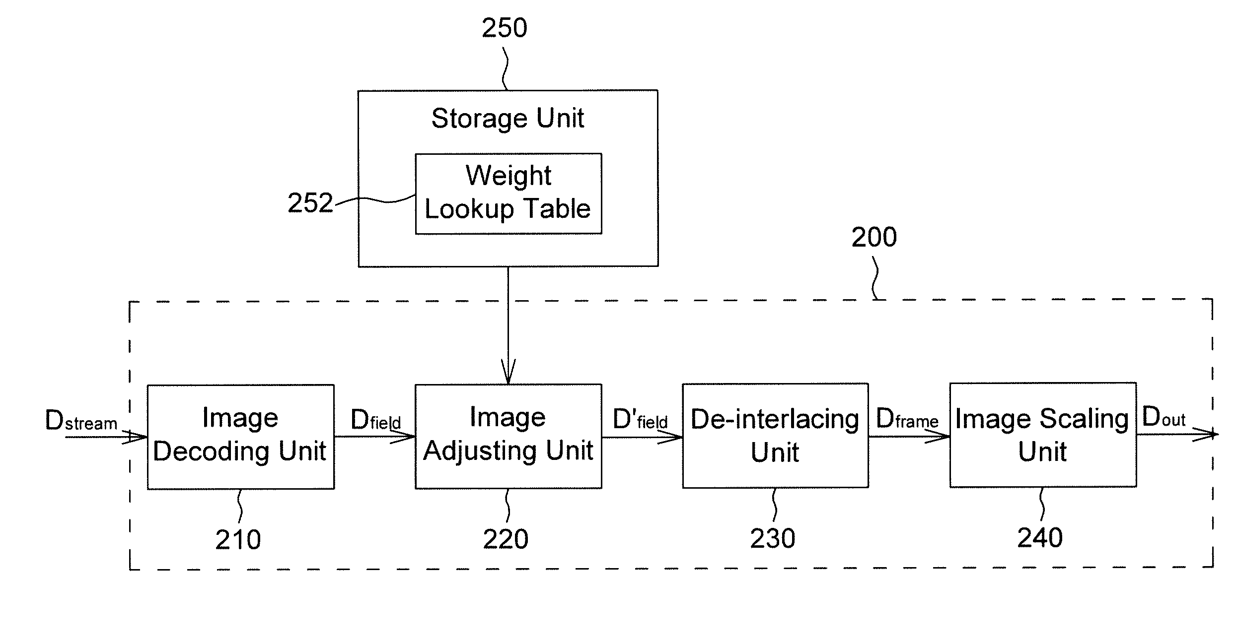
[0011] FIG. 2A is a schematic diagram of an image processing apparatus in accordance with a first embodiment of the present invention.
[0012] FIG. 2B is a schematic diagram of an image adjusting module shown in FIG. 2A.
[0013] FIG. 3 is a flow chart of an image processing method performed by the image processing apparatus in FIG. 2A and FIG. 2B on a data stream.
[0014] FIG. 4 is a schematic diagram of a plurality of fields.
[0015] FIG. 5 is a schematic diagram for illustrating a cross-color edge value and a real-color edge value of an image frame.
[0016] FIG. 6 is a diagram of a curve showing characteristics of a motion parameter value and a weight.
[0017] FIG. 7 is a schematic diagram of an image processing apparatus in accordance with a second embodiment of the present invention.
DETAILED DESCRIPTION OF THE PREFERRED EMBODIMENT
[0018] FIG. 2A and FIG. 2B show schematic diagrams of an image processing apparatus 200 in accordance with a first embodiment of the present invention. The image processing apparatus 200 comprises an image decoding unit 210, an image adjusting unit 220, a de-interlacing unit 230, and an image scaling unit 240. The image adjusting unit 220, coupled to a storage unit 250, comprises a luminance motion calculating module 221, a chrominance motion calculating module 222, a chrominance adjusting module 224, and a chrominance averaging module 225. The chrominance motion calculating module 222 comprises a chrominance motion parameter adjusting module 223. It is to be noted that, the chrominance averaging module 225 is an optional component, and is not used in all embodiments of the present invention. The storage unit 250 comprises a weight lookup table 252. In addition, the image processing apparatus 200 could be realized by hardware or software.
[0019] The description below is given with reference to FIG. 2A, FIG. 2B and FIG. 3. FIG. 3 is a flow chart of performing image processing by the image processing apparatus 200 on a data stream D.sub.stream. In Step 300, the image decoding unit 210 decodes the data stream D.sub.stream to generate a plurality of fields D.sub.field in FIG. 4. The fields D.sub.field comprise a previous even field F.sub.0.sub.--.sub.even, a previous odd field F.sub.0.sub.--.sub.odd, a current even field F.sub.1.sub.--.sub.even, and a current odd field F.sub.1.sub.--.sub.odd. Each of the fields F.sub.0.sub.--.sub.even, F.sub.0.sub.--.sub.odd, F.sub.1.sub.--.sub.even and F.sub.1.sub.--.sub.odd comprises an initial luminance value and an initial chrominance value of each pixel (i.e., P.sub.11, P.sub.12, P.sub.13 . . . ). For example, the initial luminance value is a directly decoded original luminance value or is a noise-processed luminance value; likewise, the initial chrominance value is a directly decoded original chrominance value or is a noise-processed chrominance value. In addition, the fields F.sub.0.sub.--.sub.even and F.sub.1.sub.--.sub.even have a pixel at a same position on an image, i.e., positions of the pixels P.sub.11, P.sub.12, P.sub.13, . . . , of the fields F.sub.0.sub.--.sub.even and F.sub.1.sub.--.sub.even are the same on the image.
[0020] In Step 302, for a pixel at a target position of the current field F.sub.1.sub.--.sub.even, the luminance motion calculating module 221 calculates a luminance difference between luminance values of the pixel at the target position of the current field F.sub.1.sub.--.sub.even and the previous field F.sub.0.sub.--.sub.even, and generates a luminance motion parameter Ymv according to at least the luminance difference. Taking the pixel P.sub.13 in the current field F.sub.1.sub.--.sub.even as an example, i.e., supposing that the pixel P.sub.13 is the pixel at the target position, the luminance motion parameter Ymvp.sub.13 of the pixel P.sub.13 is calculated using one of the formulae below.
Ymv.sub.P13=|Y.sub.13.sub.--.sub.1-Y.sub.13.sub.--.sub.0| (1)
Ymv.sub.P13=a.sub.1*|Y.sub.11.sub.--.sub.1-Y.sub.11.sub.--.sub.0|+a.sub.- 2*|Y.sub.12.sub.--.sub.1-Y.sub.12.sub.--.sub.0|+a.sub.3*|Y.sub.13.sub.--.s- ub.1-Y.sub.13.sub.--.sub.0|+a.sub.4*|Y.sub.14.sub.--.sub.1-Y.sub.14.sub.--- .sub.0|+a.sub.5*|Y.sub.15.sub.--.sub.1-Y.sub.15.sub.--.sub.0| (2)
Wherein, Y.sub.11.sub.--.sub.1, Y.sub.12.sub.--.sub.1, Y.sub.13.sub.--.sub.1, Y.sub.14.sub.--.sub.1 and Y.sub.15.sub.--.sub.1 are respectively initial luminance values of the pixels P.sub.11, P.sub.12, P.sub.13, P.sub.14 and P.sub.15 in the current field F.sub.1.sub.--.sub.even, Y.sub.11.sub.--.sub.0, Y.sub.12.sub.--.sub.0, Y.sub.13.sub.--.sub.0, Y.sub.14.sub.--.sub.0 and Y.sub.15.sub.--.sub.0 are respectively initial luminance values of the pixels P.sub.11, P.sub.12, P.sub.13, P.sub.14 and P.sub.15 in the previous field F.sub.0.sub.--.sub.even, and a.sub.1 to a.sub.5 are constants (e.g., a.sub.1, a.sub.2, a.sub.3, a.sub.4 and a.sub.5 respectively equal to (1/8, 1/4, 1/4, 1/4, 1/8)).
[0021] It is to be noted that, the foregoing formulae for calculating the luminance motion parameter Ymvp.sub.13 are disclosed for illustration purposes, and other approaches may also be applied to calculate the luminance motion parameter Ymvp.sub.13, e.g., a luminance motion parameter is calculated according to a luminance difference between two neighboring pixels in a two-dimensional spatial domain. Taking a pixel P.sub.22 in the current field F.sub.1.sub.--.sub.even as an example, a luminance motion parameter Ymvp.sub.22 of the pixel P.sub.22 is calculated as:
Ymv.sub.P22=a.sub.11*|Y.sub.11.sub.--.sub.1-Y.sub.11.sub.--.sub.0|+a.sub- .12*|Y.sub.12.sub.--.sub.1-Y.sub.12.sub.--.sub.0|+a.sub.13*|Y.sub.13.sub.-- -.sub.1-Y.sub.13.sub.--.sub.0|+a.sub.21*|Y.sub.21.sub.--.sub.1-Y.sub.21.su- b.--.sub.0|+a.sub.22*|Y.sub.22.sub.--.sub.1-Y.sub.22.sub.--.sub.0|+a.sub.2- 3*|Y.sub.23.sub.--.sub.1-Y.sub.23.sub.--.sub.0|+a.sub.31*|Y.sub.31.sub.--.- sub.1-Y.sub.31.sub.--.sub.0|+a.sub.32*|Y.sub.32.sub.--.sub.1-Y.sub.32.sub.- --.sub.0|+a.sub.33*|Y.sub.33.sub.--.sub.1-Y.sub.33.sub.--.sub.0| (3)
Wherein, Y.sub.11.sub.--.sub.1 to Y.sub.33.sub.--.sub.1 are respectively initial chrominance values of pixels P.sub.11 to P.sub.33 in the current field F.sub.1.sub.--.sub.even, Y.sub.11.sub.--.sub.0 to Y.sub.33.sub.--.sub.0 are respectively initial luminance values of the pixels P.sub.11 to P.sub.33, and a.sub.11 to a.sub.33 are constants. It is to be noted that a luminance motion parameter of a pixel P.sub.xy is determined according to a luminance difference between luminance values of the pixel P.sub.xy at the current field F.sub.1.sub.--.sub.even and at the previous field F.sub.0.sub.--.sub.even. In practice, a designer can obtain the luminance motion parameter of the pixel P.sub.xy via other calculation formulae according to different design considerations.
[0022] After that, in Step 304, for the pixel at the target position of the current field F.sub.1.sub.--.sub.even, the chrominance motion calculating module 222 calculates a chrominance difference between chrominance values of the pixel at the target position of the current field F.sub.1.sub.--.sub.even and the previous field F.sub.0.sub.--.sub.even, and generates a chrominance motion parameter Cmv according to at least the luminance difference. Taking the pixel P.sub.13 in the current field F.sub.1.sub.--.sub.even as an example, i.e., supposing that the pixel P.sub.13 is the pixel at the target position, the luminance motion parameter Cmvp.sub.13 of the pixel P.sub.13 is calculated using one of the formulae below.
Cmv.sub.P13=|C.sub.13.sub.--.sub.1-C.sub.13.sub.--.sub.0 (4)
Cmv.sub.P13a.sub.1*|C.sub.11.sub.--.sub.1-C.sub.11.sub.--.sub.0|+a.sub.2- *|C.sub.12.sub.--.sub.1-C.sub.12.sub.--.sub.0|+a.sub.3*|C.sub.13.sub.--.su- b.1-C.sub.13.sub.--.sub.0|+a.sub.4*|C.sub.14.sub.--.sub.1-C.sub.14.sub.--.- sub.0|+a.sub.5*|C.sub.15.sub.--.sub.1-C.sub.15.sub.--.sub.1| (5)
Wherein, C.sub.11.sub.--.sub.1, C.sub.12.sub.--.sub.1, C.sub.13.sub.--.sub.1, C.sub.14.sub.--.sub.1 and C.sub.15.sub.--.sub.1 are respectively initial chrominance values of the pixels P.sub.11, P.sub.12, P.sub.13, P.sub.14 and P.sub.15 in the current field F.sub.1.sub.--.sub.even, C.sub.11.sub.--.sub.0, C.sub.12.sub.--.sub.0, C.sub.13.sub.--.sub.0, C.sub.14.sub.--.sub.0 and C.sub.15.sub.--.sub.0 are respectively initial chrominance values of the pixels P.sub.11, P.sub.12, P.sub.13, P.sub.14 and P.sub.15 in the previous field F.sub.0.sub.--.sub.even, and a.sub.1 to a.sub.5 are constants. It is to be noted that, either the chrominance component U (or Cb) and or the chrominance component V (or Cr), or both of the chrominance components U (or Cb) and V (or Cr) can be regarded as the initial chrominance values for calculating the foregoing chrominance motion parameter. In addition, the chrominance motion parameter Cmv is calculated according to a chrominance difference between two neighboring pixels in a two-dimensional spatial domain, and the approach for calculating the chrominance motion parameter Cmv are similar to that for calculating the luminance motion parameter Ymv, such that details thereof shall not be described for brevity. Provided that the chrominance motion parameter of a pixel P.sub.xy is determined according to a chrominance difference between chrominance values of the pixel P.sub.xy at the current field F.sub.1.sub.--.sub.even and the previous field F.sub.0.sub.--.sub.even, a designer can obtain the chrominance motion parameter of the pixel P.sub.xy via other calculation formulae according to different design considerations.
[0023] An objective of calculating the luminance motion parameter Ymv and the chrominance motion parameter Cmv is to represent a degree of motion of an object on an image (i.e., the current field F.sub.1.sub.--.sub.even). More specifically, when one of the luminance motion parameter Ymv and the chrominance motion parameter Cmv of a pixel is large, it means that an object corresponding to the pixel on an image is in motion or a variation exists. When both of the luminance motion parameter Ymv and the chrominance motion parameter Cmv of the pixel are small, it means that an object corresponding to the pixel on the image is substantially static.
[0024] However, when cross-color accompanies static image, for a pixel at a target position within an area in which cross-color occurs, chrominance values of the pixel at the target position of two corresponding successive images (i.e. the current field F.sub.1.sub.--.sub.even and the previous field F.sub.0.sub.--.sub.even) are respectively C+.DELTA.C and C-.DELTA.C, where C is an ideal chrominance value of the pixel at the target pixel, and .DELTA.C is a chrominance deviation caused by high frequency luminance effect. It is to be noted that, the initial chrominance values of the fields D.sub.field decoded by the image decoding unit 210 are already undesirably affected by cross-color, i.e., the initial chrominance values of the fields D.sub.field are in fact C+.DELTA.C and C-.DELTA.C. Therefore, since the image is static, a chrominance motion parameter Cmv is calculated as 2*.DELTA.C (Cmv=|(C+.DELTA.C)-(C-.DELTA.C|) using the foregoing Formula 1 for calculating the chrominance motion parameter Cmv; however, in theory, the chrominance motion parameter Cmv should be zero since the chrominance values of the pixel at the target position of two corresponding successive images are the same for that the images are static. Accordingly, the static images are mistakenly determined as motion images to thereby create errors in the subsequent image processing.
[0025] In order to solve the foregoing problem that a chrominance motion parameter Cmv fails to truly represent a degree of motion of an image, in Step 306, the chrominance parameter adjusting module 223 of the chrominance motion calculating module 222 generates a cross-color edge value CCEV according to the initial chrominance value of the pixel at the target position and an initial chrominance value of at least one pixel neighboring to the pixel at the target pixel. The cross-color edge value CCEV is for solving the problem that a chrominance motion parameter Cmv fails to truly represent a degree of motion of an image frame due to cross-color. Taking the pixel P.sub.13 in the current field F.sub.1.sub.--.sub.even as an example, when the image frame is in a conventional YUV444 format, a cross-color edge value CCEVp.sub.13 of the pixel P.sub.13 is calculated as:
CCEV.sub.P13=b.sub.1*|C.sub.12.sub.--.sub.1-C.sub.11.sub.--.sub.1|+b.sub- .2*|C.sub.13.sub.--.sub.1-C.sub.12.sub.--.sub.1|+b.sub.3*|C.sub.14.sub.--.- sub.1-C.sub.13.sub.--.sub.1|+b.sub.4*|C.sub.15.sub.--.sub.1-C.sub.14.sub.-- -.sub.1| (6)
Wherein, C.sub.11.sub.--.sub.1, C.sub.12.sub.--.sub.1, C.sub.13.sub.--.sub.1, C.sub.14.sub.--.sub.1 and C.sub.15.sub.--.sub.1 are respectively initial chrominance values of the pixels P.sub.11, P.sub.12, P.sub.13, P.sub.14 and P.sub.15 in the current field F.sub.1.sub.--.sub.even, and b.sub.1 to b.sub.5 are constants. In addition, either the chrominance component U or chrominance component V, or both of the chrominance components U and V can be regarded as the initial chrominance values for calculating the foregoing cross-color edge value CCEV. When the image frame is in a conventional YUV422 format, the cross-color edge value CCEVp.sub.13 of the pixel P.sub.13 is calculated as:
CCEV.sub.P13=c.sub.1*|C.sub.13.sub.--.sub.1-C.sub.11.sub.--.sub.1|+c.sub- .2*|C.sub.14.sub.--.sub.1-C.sub.12.sub.--.sub.1|+c.sub.3*|C.sub.15.sub.--.- sub.1-C.sub.13.sub.--.sub.1| (7)
Wherein, C.sub.1, C.sub.2 and C.sub.3 are constants.
[0026] It is to be noted that, other calculation approaches can be applied to calculate a cross-color edge value CCEV, provided that a cross-color edge value CCEV of a pixel P.sub.xy is determined according to a an initial chrominance value of the pixel P.sub.xy and an initial chrominance value of at least one pixel neighboring to the pixel P.sub.xy, and a designer can obtain the cross-color edge value CCEV of the pixel P.sub.xy using other formulae according to the YUV format (e.g., 444 or 422) or different design considerations.
[0027] A reason for adjusting a chrominance motion parameter Cmv with a cross-color edge value CCEV is described below. Under two situations, the chrominance motion parameter Cmv may be rather large--a first situation is that an object having a significant color difference from a background of an image frame moves (e.g., a red ball rolls across green lawns) and a second situation that cross-color occurs in a static image frame. Under the first situation, the chrominance motion parameter Cmv does truly reflect that there is a moving object in the image; however, under the second situation, the chrominance motion parameter Cmv may mistakenly determine that there is a moving object in the image (i.e., the chrominance motion parameter Cmv calculated by the chrominance motion calculating module 222 is large (e.g., 2*.DELTA.C) when in fact the image frame is static.) Therefore, the cross-color edge value CCEV is a parameter indicating whether cross-color occurs in an image, whereas the significance for calculating the cross-color edge value CCEV is to be described below. Generally speaking, when cross-color occurs in an area of an image, the chrominance of the area in spatial domain may drastically change, which is referred to as high frequency chrominance (i.e., the variance of chrominance in spatial domain is high). However, in a normal image frame, the spatial changes in chrominance are mild (i.e., the spatial frequency of chrominance space is relatively low). Therefore, when a cross-color edge value CCEV at a target position is large, it means that the target position is within an area in which cross-color occurs; when the cross-color edge value CCEV at the target position is small, it means that the area comprising the target position is free of cross-color.
[0028] Therefore, a chrominance motion parameter Cmv may be adjusted via a cross-color edge value CCEV, such that an adjusted chrominance motion parameter C'mv can accurately reflect a degree of motion of a pixel at a target position of an image. Taking the pixel P.sub.13 of the current field F.sub.1.sub.--.sub.even as an example, the adjusted chrominance motion parameter C'mv is calculated as:
C'mv.sub.P13=Cmv.sub.P13-CCEV.sub.P13 (8)
Wherein, Cmvp.sub.13 is a chrominance motion parameter of the pixel P.sub.13 calculated in Step 304, and CCEVp.sub.13 is a cross-color edge value CCEV of the pixel P.sub.13 calculated in Step 306.
[0029] As mentioned above, when an image frame is static, the chrominance motion parameter Cmv and the cross-color edge value CCEV may be large. The adjusted chrominance motion parameter C'mv generated from subtracting the chrominance motion parameter Cmv from the cross-color edge value CCEV using the foregoing Formula (8) may be small and can truly reflect the static image.
[0030] Therefore, the implementation of the cross-color edge value CCEV is capable of adjusting the chrominance motion parameter Cmv to avoid cross-color from being considered as a moving object in the image. However, under a special situation below, adjustment performed by adding the cross-color edge value CCEV still cannot solve the issue of cross-color occurring at motion edges of the object. Referring to FIG. 5 showing two successive frames F.sub.0 and F.sub.1, the frame F.sub.0 is a previous image comprising the fields F.sub.0.sub.--.sub.even and F.sub.0.sub.--.sub.dd in FIG. 4, and the frame F.sub.1 is a current image comprising the fields F.sub.1.sub.--.sub.even and F.sub.1.sub.--.sub.dd in FIG. 4. The frames F.sub.0 and F.sub.1 display that a red ball 510 rolls across a green lawn, i.e., backgrounds of the frames F.sub.0 and F.sub.1 are green. Accordingly, an adjusted chrominance motion parameter C'mv of a pixel P.sub.tar at a target position of the frame F.sub.1 is underestimated (e.g., the pixel P.sub.tar at a same position of the frame F.sub.0 and the frame F.sub.1 in FIG. 5). More specifically, since the pixel P.sub.tar at the target position is located at the green background (corresponding to edges of the red ball 510 in the previous frame F.sub.0) of the frame F.sub.1, a chrominance motion parameter Cmv of the pixel P.sub.tar is supposedly large (i.e., the green part of the image frame F.sub.1 and the red part of the image frame F.sub.0). However, the chrominance motion parameter Cmv of the pixel P.sub.tar calculated according to Formula (5) is smaller than an actual value since an average chrominance value of neighboring pixels is added in Formula (5). Therefore, the adjusted chrominance motion parameter C'mv calculated according to Formula (8) is smaller than an actual value, such that chrominance of the pixel P.sub.tar cannot be accurately adjusted.
[0031] Therefore, in order to solve the abovementioned problem, in Step 308, the chrominance motion parameter adjusting module 223 generates a real-color edge value RCEV according to at least a plurality of initial chrominance values of a plurality of neighboring pixels of the pixel at the target pixel at the field F.sub.0.sub.--.sub.even and a plurality of initial chrominance values of the plurality of neighboring pixels of the pixel at the target pixel at the field F.sub.1.sub.--.sub.even, and further adjusts the cross-color edge value CCEV with the real-color edge value RCEV. Taking the pixel P.sub.13 at the current fields F.sub.1.sub.--.sub.even as an example, a real-color edge value RCEV of the pixel P.sub.13 is calculated as:
C'.sub.11=(C.sub.11.sub.--.sub.1+C.sub.11.sub.--.sub.0)/2;
C'.sub.12=(C.sub.12.sub.--.sub.1+C.sub.12.sub.--.sub.0)/2;
C'.sub.13=(C.sub.13.sub.--.sub.1+C.sub.13.sub.--.sub.0)/2;
C'.sub.14=(C.sub.14.sub.--.sub.1+C.sub.14.sub.--.sub.0)/2;
C'.sub.15=(C.sub.15.sub.--.sub.1+C.sub.15.sub.--.sub.0)/2;
RCEV.sub.P13h.sub.1*|C'.sub.12-C'.sub.11|+h.sub.2*|C'.sub.13-C'.sub.12|+- h.sub.3*|C'.sub.14-C'.sub.13|+h.sub.4*|C'.sub.15-C'.sub.14| (9)
Wherein, C.sub.11.sub.--.sub.1 to C.sub.15.sub.--.sub.1 are respectively chrominance values of the pixels P.sub.11 to P.sub.15 at the field F.sub.1.sub.--.sub.even, C.sub.11.sub.--.sub.0 to C.sub.15.sub.--.sub.0 are respectively chrominance values of the pixels P.sub.11 to P.sub.15 at the field F.sub.0.sub.--.sub.even, and h.sub.1 to h.sub.4 are constants. In addition, either the chrominance component U or the chrominance component V, or both of the chrominance components U and V can be regarded as the initial chrominance values for calculating the real-color edge value RCEV. Provided that the real-color edge value RCEV of the pixel P.sub.xy is determined according to a chrominance difference between chrominance values of the pixel P.sub.xy at the current field F.sub.1.sub.--.sub.even and the previous field F.sub.0.sub.--.sub.even, a designer can obtain the real-color edge value RCEV of the pixel P.sub.xy using different formulae according to other design considerations.
[0032] When the calculated real-color edge value RCEV of the pixel P.sub.xy is large, it means that the pixel P.sub.xy is at the edge of the moving object in FIG. 5; when the calculated real-color edge value RCEV of the pixel P.sub.xy is small, it means that the pixel P.sub.xy may be within an area having a small chrominance variation.
[0033] In Step 310, the chrominance motion parameter Cmv may be adjusted via the cross-color edge value CCEV and the real-color edge value RCEV, so that the adjusted chrominance motion parameter C'mv can truly represent a degree of motion of the pixel at the target position of the image frame. Taking the pixel P.sub.13 at the current field F.sub.1.sub.--.sub.even as an example, an adjusted chrominance motion parameter C'mvp.sub.13 is calculated as:
C'mv.sub.P13=Cmv.sub.P13-CCEV.sub.P13+RCEV.sub.P13 (10)
Wherein, Cmvp.sub.13 is the chrominance motion parameter of the pixel P.sub.13, calculated in Step 304, CCEVp.sub.13 is the cross-color edge value of the pixel P.sub.13 calculated in Step 306, and RCEVp.sub.13 is the real-color edge value of the pixel P.sub.13 calculated in Step 308.
[0034] After that, in Step 312, the chrominance adjusting module 224 generates a motion parameter MV according to the luminance motion parameter Ymv and the adjusted chrominance motion parameter C'mv. Taking the pixel P.sub.13 at the current field F.sub.1.sub.--.sub.even as an example, an motion parameter MVp.sub.13 is calculated as (but not limited to):
MV.sub.P13=Max{Ymv.sub.P13,C'mv.sub.P13} (11)
MV.sub.P13=d.sub.1*Ymv.sub.P13+d.sub.2*C'mv.sub.P13 (12)
Wherein, Max { } is a maximum operator, Ymvp.sub.13 is a luminance motion parameter of the pixel P13, C'mvp.sub.13 is an adjusted chrominance motion parameter of the pixel P.sub.13, and d.sub.1 and d.sub.2 are constants.
[0035] In Step 314, the chrominance module 224 calculates a weight W according to the motion parameter MV, and the weight W is determined according to the characteristic curve in FIG. 6 or the weight lookup table 252 stored in the storage unit 250 in FIG. 2A.
[0036] In Step 316, the chrominance adjusting module 224 by weighted averaging an initial chrominance value C of the pixel at the target position of the current field F.sub.1.sub.--.sub.even and an initial chrominance value of the pixel at the target position of the previous field F.sub.0.sub.--.sub.even to generate an adjusted chrominance value C'. Taking the pixel P.sub.13 at the current field F.sub.1.sub.--.sub.even as an example, an adjusted chrominance value C'.sub.13.sub.--.sub.1 is calculated as:
C'.sub.13.sub.--.sub.1=W*C.sub.13.sub.--.sub.0+(1-W)*C.sub.13.sub.--.sub- .1 (13)
Wherein, C.sub.13.sub.--.sub.0 is an initial chrominance value of the pixel P.sub.13 at the previous field F.sub.0.sub.--.sub.even, and C.sub.13.sub.--.sub.1 is an initial chrominance value of the pixel P.sub.13 at the current field F.sub.1.sub.--.sub.even.
[0037] Inferred from Step 314 and Step 316, when an object in an image moves (or the image varies), a motion parameter MV of the pixel corresponding to the object is large, and the weight W calculated in Step 314 is accordingly small. Taking the P.sub.13 at the current field F.sub.1.sub.--.sub.even as an example, supposing that the weight W is 0.1, an adjusted chrominance value C'.sub.13 of the pixel P.sub.13 is calculated as:
C'.sub.13.sub.--.sub.1=0.1*C.sub.13.sub.--.sub.0+0.9*C.sub.13.sub.--.sub- .1 (14)
Accordingly, the adjusted chrominance value C'.sub.13.sub.--.sub.1 approximates the initial chrominance value C.sub.13.sub.--.sub.1, i.e, only a little cross-color compensation is performed on the pixel P.sub.13. When the image frame is static, the motion parameter MV of the pixel is equal to zero (or smaller than zero). Therefore, the weight W calculated in Step 314 is equal to 0.5. Taking the P.sub.13 at the current field F.sub.1.sub.--.sub.even as an example, the adjusted chrominance value C'.sub.13 is calculated as:
C'.sub.13.sub.--.sub.1=0.5*C.sub.13.sub.--.sub.0+0.5*C.sub.13.sub.--.sub- .1 (15)
That is, complete cross-color compensation is performed on the pixel P.sub.13.
[0038] In another embodiment of the present invention, the chrominance averaging module 225 averages the initial chrominance value C of the pixel at the target position of the current field F.sub.1.sub.--.sub.even and the initial chrominance value of the pixel at the target position of the previous field F.sub.0.sub.--.sub.even to generate an average chrominance value C'' of the pixel at the target pixel of the current field F.sub.1.sub.--.sub.even. In Step 314 to Step 316, a weight W.sub.1 is calculated according to the motion parameter MV and an adjusted chrominance value C' is calculated according to W.sub.1 by weighted averaging the initial chrominance value C of the pixel at the target position of the current field F.sub.1.sub.--.sub.even and the average chrominance value C'' of the pixel at the target pixel of the current field F.sub.1.sub.--.sub.even. Taking the P.sub.13 at the current field F.sub.1.sub.--.sub.even as an example, an average chrominance value C''.sub.13.sub.--.sub.1 and an adjusted chrominance value C'.sub.13 are calculated as:
C''.sub.13.sub.--.sub.1=0.5*C.sub.13.sub.--.sub.0+0.5*C.sub.13.sub.--.su- b.1; and
C'.sub.13.sub.--.sub.1=W.sub.1*C''.sub.13.sub.--.sub.1+(1''W.sub.1)*C.su- b.13.sub.--.sub.1.
Wherein, a relationship between the weight W.sub.1 and the motion parameter MV is almost the same as that of the weight W and the motion parameter MV. More specifically, the weight W.sub.1 ranges from 0 to 1, i.e., when the pixel at the target position of the image frame moves (when the motion parameter MV is large), the weight W.sub.1 approximates 0, and the adjusted chrominance value C'.sub.13.sub.--.sub.1 approximates C.sub.13.sub.--.sub.1; in contrast, when the image is static (when the motion parameter MV of the pixel is equal to 0 or 1), the weight W.sub.1 approximates 1, and the adjusted chrominance value C'.sub.13.sub.--.sub.1 is equal to C''.sub.13.sub.--.sub.1, i.e., a complete cross-color compensation is performed on the pixel P.sub.13.
[0039] In conclusion, the foregoing Step 312 to Step 316 merely describe an embodiment of the present invention and are not construed as limiting the present invention, i.e., provided that the chrominance adjusting unit 224 determines a weight of an initial chrominance value of a pixel at a target position of the previous field F.sub.0.sub.--.sub.even and a weight of an initial chrominance value of the pixel at the target position of the current field F.sub.1.sub.--.sub.even according to a luminance motion parameter Ymv of the pixel at the target pixel and an adjusted chrominance motion parameter C'mv, and at least one of the luminance motion parameter Ymv and the adjusted chrominance motion parameter C'mv is inversely associated with the weight of the initial chrominance value of the pixel at the target position of the previous field F.sub.0.sub.--.sub.even) proper modifications made are within the scope and spirit of the present invention.
[0040] The abovementioned chrominance adjusting operation is performed on all pixels at the field F.sub.1.sub.--.sub.even, and a plurality of chrominance-adjusted fields D.sub.field' are generated and provided to the de-interlacing unit 230.
[0041] In Step 318, the de-interlacing unit 230 performs de-interlacing on the plurality of chrominance-adjusted fields D.sub.field' to generate a plurality of frames D.sub.frame. In Step 320, the image scaling unit 240 performs scaling on the plurality of frames D.sub.frame to generate a display images D.sub.out to a display.
[0042] It is to be noted that, in the foregoing description of the image processing apparatus 200 in FIG. 2 to FIG. 6, the field F.sub.0.sub.--.sub.even is a previous even field before the field F.sub.1.sub.--.sub.even. As for a pixel at a same target position of the fields F.sub.0.sub.--.sub.even and F.sub.1.sub.--.sub.even an a chrominance value of the pixel at the target position of the field F.sub.1.sub.--.sub.even is adjusted according to pixels of the fields F.sub.0.sub.--.sub.even and F.sub.1.sub.--.sub.even. However, in other embodiments of the present invention, the field F.sub.0.sub.--.sub.even may be a next even field of the field F.sub.1.sub.--.sub.even, and a chrominance value of the pixel at the target of the field F.sub.1.sub.--.sub.even is also adjusted according to pixel of the fields F.sub.0.sub.--.sub.even and F.sub.1.sub.--.sub.even. A related calculation approach is the same as described in the flow of FIG. 3, i.e., the next even field of the field F.sub.1.sub.--.sub.even is regarded as the field F.sub.0.sub.--.sub.even. Such modifications of the embodiments are apparent to a person having ordinary skill in the art, and details thereof shall not be described for brevity.
[0043] It is to be noted that, in the embodiment shown in FIG. 3, the chrominance adjusting unit 224 generates a motion parameter MV according to a luminance motion parameter Ymv, and an adjusted chrominance motion parameter C'mv that is generated according to a chrominance motion parameter Cmv, a cross-color edge value CCEV and a real-color edge value RCEV. However, in other embodiments of the present invention, the adjusted chrominance motion parameter C'mv is generated according to the cross-color edge value CCEV (i.e., the adjusted chrominance motion parameter C'mv is calculated using Formula (8)). After that, the image adjusting unit 220 generates the motion parameter MV according to the luminance motion parameter Ymv and the adjusted chrominance motion parameter C'mv calculated using Formula (8). In addition, the image adjusting unit 220 can even generate the motion parameter MV according to the luminance motion parameter Ymv and the chrominance motion parameter Cmv, and such design modifications are also within the scope and spirit of the present invention.
[0044] FIG. 7 shows a schematic diagram of an image processing apparatus 700 in accordance with a second embodiment of the present invention. The image processing apparatus comprises an image decoding unit 710, a de-interlacing unit 720, an image adjusting unit 730, and an image scaling unit 740, wherein the image adjusting unit 730 is coupled to a storage unit 750 comprising a weight lookup table 752. In addition, the image processing apparatus 700 is realized by hardware or software.
[0045] A difference between the image processing apparatus 700 and the image processing apparatus 200 in FIG. 2A is that the image adjusting unit 220 of the image processing apparatus 200 performs image adjusting with respect to fields, and the image adjusting unit 730 of the image processing apparatus 700 performs image adjusting with respect to frames. In addition, operations of the image adjusting unit 730 are similar to those of the image adjusting unit 220, and a person having ordinary skill in the art can easily infer an operation flow of the image processing apparatus 700 with reference to the description associated with the image processing apparatus 200, such that details thereof shall not be described for brevity.
[0046] In conclusion, an image processing apparatus provided by the present invention determines a degree of cross-color compensation according to whether an image moves, and provides conceptions of determining whether the image moves according to a luminance motion parameter, a chrominance motion parameter, a cross-color edge value and a real-color edge value, so that the image processing apparatus can accurately determine whether the image moves or varies to further perform an optimal cross-color compensation according to a degree of motion or variation of the image, thereby improving quality of the image.
[0047] While the invention has been described in terms of what is presently considered to be the most practical and preferred embodiments, it is to be understood that the invention needs not to be limited to the above embodiments. On the contrary, it is intended to cover various modifications and similar arrangements included within the spirit and scope of the appended claims which are to be accorded with the broadest interpretation so as to encompass all such modifications and similar structures.
* * * * *
D00000
D00001
D00002
D00003
D00004
D00005
D00006
D00007
D00008
XML
uspto.report is an independent third-party trademark research tool that is not affiliated, endorsed, or sponsored by the United States Patent and Trademark Office (USPTO) or any other governmental organization. The information provided by uspto.report is based on publicly available data at the time of writing and is intended for informational purposes only.
While we strive to provide accurate and up-to-date information, we do not guarantee the accuracy, completeness, reliability, or suitability of the information displayed on this site. The use of this site is at your own risk. Any reliance you place on such information is therefore strictly at your own risk.
All official trademark data, including owner information, should be verified by visiting the official USPTO website at www.uspto.gov. This site is not intended to replace professional legal advice and should not be used as a substitute for consulting with a legal professional who is knowledgeable about trademark law.