Ap-local Dynamic Switching
Murphy; James ; et al.
U.S. patent application number 12/304100 was filed with the patent office on 2010-12-30 for ap-local dynamic switching. Invention is credited to Stan Chestnut, Gary Eugene Morain, James Murphy.
| Application Number | 20100329177 12/304100 |
| Document ID | / |
| Family ID | 43380630 |
| Filed Date | 2010-12-30 |


| United States Patent Application | 20100329177 |
| Kind Code | A1 |
| Murphy; James ; et al. | December 30, 2010 |
AP-LOCAL DYNAMIC SWITCHING
Abstract
A technique for implementing AP-local dynamic switching involves Layer 2 switching. This may be accomplished by providing data associated with wireless stations to an AP sufficient to enable the AP to determine whether traffic from a particular wireless station should be locally switched. Alternatively, the wireless station may be able to determine whether to locally switch traffic based upon the traffic itself. For example, it may be desirable to AP-locally switch voice traffic to avoid latency, which is particularly detrimental to voice transmissions such as voice-over-IP. Traffic that is not to be switched locally is Layer 2 tunneled upstream.
| Inventors: | Murphy; James; (San Jose, CA) ; Morain; Gary Eugene; (San Jose, CA) ; Chestnut; Stan; (Berkeley, CA) |
| Correspondence Address: |
    PERKINS COIE LLP
    P.O. BOX 1208
    SEATTLE
    WA
    98111-1208
    US
|
| Family ID: | 43380630 |
| Appl. No.: | 12/304100 |
| Filed: | June 11, 2007 |
| PCT Filed: | June 11, 2007 |
| PCT NO: | PCT/US07/13757 |
| 371 Date: | August 6, 2010 |
Related U.S. Patent Documents
| Application Number | Filing Date | Patent Number | ||
|---|---|---|---|---|
| 11801964 | May 11, 2007 | |||
| 12304100 | ||||
| 60812403 | Jun 9, 2006 | |||
| Current U.S. Class: | 370/328 |
| Current CPC Class: | H04W 40/02 20130101; H04W 84/22 20130101; H04W 88/14 20130101; H04W 76/12 20180201; H04W 84/18 20130101; H04W 12/06 20130101; H04W 8/082 20130101; H04W 80/02 20130101 |
| Class at Publication: | 370/328 |
| International Class: | H04W 88/08 20090101 H04W088/08 |
Claims
1. An access point (AP) apparatus comprising: a radio; a processor; a dynamic switching module implemented in a computer readable medium coupled to the radio and the processor; a station switching record (SSR) database, coupled to the dynamic switching module, including an SSR associated with a wireless station; wherein, in operation: traffic is received on the radio from the wireless station; the processor executes the dynamic switching module; the dynamic switching module determines whether to switch the traffic locally at the AP or pass the traffic upstream; the traffic is sent in accordance with the determination.
2. The apparatus of claim 1, wherein, in operation, the SSR is received over the radio from an upstream source.
3. The apparatus of claim 1, wherein, the SSR includes data selected from one or more of the group consisting of station MAC, SSID, VLAN name, AAA data, and user data.
4. The apparatus of claim 1, wherein, in operation, if the dynamic switching module determines to switch the traffic locally at the AP, the traffic is sent over the radio to a downstream destination.
5. The apparatus of claim 1, wherein, in operation, if the dynamic switching module determines to switch the traffic locally at the AP, the traffic is sent over the radio to an upstream destination.
6. The apparatus of claim 1, wherein, in operation, if the dynamic switching module determines to pass the traffic upstream, the traffic is sent over the radio for switching at an upstream switch.
7. The apparatus of claim 1, further comprising an Ethernet interface.
8. The apparatus of claim 7, wherein, in operation, the SSR is received over the Ethernet interface from an upstream source.
9. The apparatus of claim 7, wherein, in operation, the traffic is sent in accordance with the determination over the Ethernet interface.
10. The apparatus of claim 7, wherein, in operation, if the dynamic switching module determines to switch the traffic locally at the AP, the traffic is sent over the Ethernet interface to an upstream destination.
11. The apparatus of claim 7, wherein, in operation, if the dynamic switching module determines to pass the traffic upstream, the traffic is sent over the Ethernet interface for switching at an upstream switch.
12. A system comprising: a wireless switch; an access point (AP) coupled to the wireless switch via a Layer 2 tunnel; a dynamic switching engine capable of determining whether to switch traffic locally at the AP or send the traffic upstream via the Layer 2 tunnel toward the wireless switch for upstream switching.
13. The system of claim 12, wherein, in operation, the dynamic switching engine switches traffic locally at the AP based upon characteristics associated with a sender of the traffic.
14. The system of claim 12, wherein, in operation, the dynamic switching engine switches traffic locally at the AP based upon characteristics of a target of the traffic.
15. The system of claim 12, wherein, in operation, the dynamic switching engine switches traffic locally at the AP based upon characteristics of the traffic.
16. The system of claim 15, wherein, in operation, the dynamic switching engine switches traffic locally at the AP if the traffic includes voice data.
17. A method comprising: receiving Layer 2 traffic from a wireless station; determining whether to switch the traffic AP-locally; if it is determined that the traffic is not to be AP-locally switched, Layer 2 tunneling the traffic upstream; if it is determined that the traffic is to be AP-locally switched, Layer 2 switching the traffic AP-locally and sending the Layer 2 switched traffic toward a destination associated with the traffic.
18. The method of claim 17, further comprising: receiving data associated with the wireless station; determining whether to switch the traffic AP-locally using the data associated with the wireless station.
19. The method of claim 17, further comprising determining whether to switch the traffic AP-locally based upon characteristics of the traffic.
20. The method of claim 17, wherein the Layer 2 switched traffic is sent toward a downstream destination.
Description
BACKGROUND
[0001] An access point (AP) is a device used by wireless clients to connect to a network. An AP functions as a standalone entity in some implementations and functions in cooperation with distribution hardware in other implementations. Distribution hardware may include a wireless switch used to manage APs and provide network-connectivity to wireless clients. A wireless domain may refer to a group of wireless switches that are configured to exchange relevant information, and using this information make informed decisions. A known device is a station (e.g., a wireless AP or client device) that is part of a network wireless installation.
[0002] Trapeze Networks, Inc. (Trapeze), uses a MOBILITY POINT.RTM. (MP.RTM.) APs in a MOBILITY DOMAIN.TM. wireless domain. An MP.RTM. AP is coupled to a MOBILITY EXCHANGE.RTM. (MX.RTM.) wireless switch. Trapeze uses MOBILITY DOMAIN.TM. to refer to a collection of MX.RTM. switches. This collection of MX.RTM. switches shares RF environment and station association information. This information is used by the MX.RTM. switches to support features including by way of example but not limitation roaming, auto channel selection, rogue AP detection, intrusion detection and/or the launching of countermeasures. Some additional details regarding the Trapeze-specific implementation is provided by way of example but not limitation, including novel features that are discussed later in this application, in the provisional application to which this application claims priority.
[0003] In a typical implementation, switching is performed, as may be expected, by the switch. However, it is also possible to perform native switching at an AP. It is a non-trivial problem to coordinate AP-local switching with centralized control. It is also a non-trivial problem to provide hybrid switching, that is, AP-local switching combined with switching at the switch.
[0004] These are but a subset of the problems and issues associated with wireless access point authentication, and are intended to characterize weaknesses in the prior art by way of example. The foregoing examples of the related art and limitations related therewith are intended to be illustrative and not exclusive. Other limitations of the related art will become apparent to those of skill in the art upon a reading of the specification and a study of the drawings.
SUMMARY
[0005] This Summary is provided to introduce a selection of concepts in a simplified form that are further described below in the Detailed Description. This Summary is not intended to identify key features or essential features of the claimed subject matter, nor is it intended to be used to limit the scope of the claimed subject matter.
[0006] A technique for implementing AP-local dynamic switching involves Layer 2 switching. This may be accomplished by providing data associated with wireless stations to an AP sufficient to enable the AP to determine whether traffic from a particular wireless station should be locally switched. Alternatively, the wireless station may be able to determine whether to locally switch traffic based upon the traffic itself. For example, it may be desirable to AP-locally switch voice traffic to avoid latency, which is particularly detrimental to voice transmissions such as voice-over-IP. Traffic that is not to be switched locally is Layer 2 tunneled upstream.
[0007] The proposed system can offer, among other advantages, efficient utilization of bandwidth, reduced latency, network efficiency, reliability. This and other advantages of the techniques described herein will become apparent to those skilled in the art upon a reading of the following descriptions and a study of the several figures of the drawings.
BRIEF DESCRIPTION OF THE DRAWINGS
[0008] Embodiments of the claimed subject matter are illustrated in the figures. However, the embodiments and figures are illustrative rather than limiting; they provide examples of the claimed subject matter.
[0009] FIG. 1 depicts an example of a system including an untethered access point (UAP) mesh.
[0010] FIG. 2 depicts an example of a AP-local dynamic switching system.
[0011] FIGS. 3A to 3D depict by way of example but not limitation various factors that could be considered when determining whether to switch locally at an AP or at a switch.
[0012] FIG. 4 depicts an example of an AP capable of AP-local dynamic switching.
[0013] FIG. 5 depicts a flowchart of an example of a method for AP-local dynamic switching.
DETAILED DESCRIPTION
[0014] In the following description, several specific details are presented to provide a thorough understanding of embodiments of the claimed subject matter. One skilled in the relevant art will recognize, however, that the claimed subject matter can be practiced without one or more of the specific details, or in combination with other components, etc. In other instances, well-known implementations or operations are not shown or described in detail to avoid obscuring aspects of various embodiments, of the claimed subject matter.
[0015] FIG. 1 depicts an example of a system 100 including an untethered access point (UAP) mesh. In the example of FIG. 1, the system 100 includes a network 102, a wireless switch 104, one or more APs 106-1 to 106-N (referred to collectively as APs 106), and a UAP mesh 108. It should be noted that while an overlay switching model is in some ways replaced by the techniques described herein, it may be desirable to prevent the implementation of local switching from removing any functionality of the overlay model.
[0016] An overlay switch model includes APs that tunnel to an upstream switch (e.g., an MX.RTM.), allowing the switch to perform complex policy and forwarding decisions locally. Centralizing switching to an upstream switch has allowed AP switching code to remain relatively simple (supporting the Thin-AP model). The AP at least knows it is on a subnet from which the upstream switch is reachable. The advantages of the overlay model include keeping the AP code and configuration simple; allowing a wireless network to be deployed over an arbitrary access network connecting the AP to the upstream switch (since client traffic is tunneled, it does not see the access network, so stations on the AP can be on completely different LANs than those available to the AP); and switches can form tunnels between themselves and send client traffic in those tunnels to further extend the choice of VLANs any given client on any AP may join. However, the overlay network suffers from the following: all traffic must pass through the upstream switch, which might be very far from the AP; complications involving MTU and other middle box issues when tunneling traffic; and not taking advantage of the distributed forwarding computational power available at the APs (in general, designs that push forwarding issues to the edge scale better).
[0017] The network 102 may include an Internet protocol (IP) network. In an embodiment, the network 102 is a wired backbone to which the wireless switch 104 is coupled. However, the network 102 may alternatively represent the network, or any other network, to which a backbone network is coupled or which acts as an alternative to a backbone network. Thus, the network 102 could include, for example, the Internet.
[0018] The wireless switch 104 is typically wire connected to the APs 106. Thus, the "wireless" switch could be thought of, depending upon the implementation, as a switch for wireless traffic to and/or from a wired network. The wireless switch 104 is not necessarily wirelessly connected to anything. Each of the APs 106 could be wire coupled to respective switches such that each switch is wire coupled to only a single AP. So, although the one or more APs 106 is depicted as a plurality in the example of FIG. 1, it should be understood that the number of APs per switch is implementation- and/or embodiment-specific. An AP and the wireless switch 104 could be combined into a single device. However, in this description, the functionality of an AP is differentiated from the functionality of a switch by acting as if the APs and the wireless switches are distinct devices.
[0019] The wireless switch 104 may or may not have all of the tools to manage wireless stations and the UAP mesh locally. For example, there may be additional management (e.g., AAA servers) further upstream from the wireless switch 104. Since it is not critical where these services take place beyond the wireless switch 104, for illustrative simplicity, it is assumed that the wireless switch 104 handles all of these functions, either locally or by utilizing upstream components. For this reasons, the figures (other than FIG. 1) do not depict components further upstream from the wireless switch 104.
[0020] Wireless data may include, by way of example but not limitation, station association data and RF environment data. The station and RF data is used by the wireless switches 104 to support features including, by way of example but not limitation, roaming, auto channel selection, rogue AP detection, intrusion detection and the launching of countermeasures. The wireless switch 104 may share wireless data with other wireless switches (not shown).
[0021] The wireless switch 104 controls the APs 106 (and the APs in the UAP mesh 108). In an embodiment, the APs 106 include radio transmitters and receivers (e.g., transceivers) that are used to provide wireless network connectivity for users and station access to the functions of the wireless switch 104. Within an IEEE 802.11 context, a station is any IEEE 802.11 entity or the equivalent in other related standards, and it may be roaming or stationary. It should be noted that this definition may include APs.
[0022] In the example of FIG. 1, each of the APs 106 anchors at least a portion of the UAP mesh 108 to the wired network. The APs 106 may be treated as border devices between the wireless switch 104 (or other upstream components of the system 100) and the UAP mesh 108. This enables more efficient use of wireless resources because proxy address resolution protocol (proxy ARP) may be used to enable the APs 106 to answer ARP requests on behalf of a remote device (e.g., a UAP for which an AP serves as an anchor to the wireless switch 104).
[0023] In a non-limiting 802.11 implementation, each of the APs 106 supports switching packets from a radio interface to a wired interface as a standard 802.3 frame. The AP switching path may or may not support 802.1q tagged packets and may or may not support MAC or user-based ACLs. (Port, VLAN, or VPORT based ACLs may or may not be required.) It may be desirable for an AP to support local switching and overlay simultaneously. However, even if it does, it is not a requirement that packets should be switched locally and in overlay mode simultaneously. For example, a given VLAN on an AP may be switched either locally or in overlay mode.
[0024] In the example of FIG. 1, the UAP mesh 108 is intended to depict a plurality of potentially discrete APs that do not have a wired connection to the wireless switch 104 or to the APs 106. That is why the APs in the wireless mesh are referred to as "untethered." Any station in the UAP mesh 108, whether a UAP or some other wireless station, is anchored to the wireless switch 104 by the AP 106 and zero or more UAPs that make up a chain of nodes from the station to the AP 106. An AP that is closer to the wireless switch 104 in the chain may be referred to as anchoring downstream stations. For any given station, the path from the station to the wireless switch 104 may be referred to as a spanning tree because the UAP mesh 108 should not allow loops for traffic passing between a station and the wireless switch 104.
[0025] When a UAP in the UAP mesh 108 is brought online, it will attempt to reach the wireless switch 104 through a path that is optimal. (Note: Although an optimal path is desired, it may or may not be accomplished in practice, depending upon the implemented algorithm and/or environmental factors). There are multiple metrics for measuring the distance of a UAP from one of the APs 106. For example, the metric may be time. That is, the amount of time it takes for a packet to travel between the UAP and the AP anchoring the UAP. Although such a metric may work fine, it will typically vary depending upon environmental factors, such as traffic congestion or degraded received signal strength. For simplicity, the metric used herein is the number of hops between the UAP and the anchoring AP (AAP), with the understanding that this is but one of many potential metrics. Thus, if a UAP is one hop away from the AAP, the UAP may be referred to as a one-hop UAP. In general, a UAP may be referred to as an N-hop UAP where the UAP is N hops from the AAP.
[0026] Advantageously, UAPs of the UAP mesh 108 may include an AP-local switching engine embodied in a computer-readable medium. An AP-local switching engine may make use of a station switching record (SSR) to determine how to switch a given message unit (e.g., a packet, frame, datagram, etc.). This enables at least some traffic to be efficiently switched within the UAP mesh 108. Moreover, advantageously, some traffic may be tunneled back to a switch, while other traffic is locally switched. Which traffic is tunneled back, and which traffic is locally switched, is an implementation-specific decision that becomes available by using the teachings described herein.
[0027] The SSR may include any information available at an upstream switch. In a non-limiting embodiment, the data available to the switch following station association and authentication includes station MAC, VLAN number, VLAN name, a local switch flag, a tagging flag, radio port, radio tag (used to map the radio port to the VLAN), ACLs (e.g., ingress and egress ACLs to be mapped to the station MAC), and/or a proxy-ARP flag. (Note: the proxy-ARP might only be honored if local switching is enabled.) In an illustrative embodiment that enables local switching for a particular VLAN (other examples are described later with reference to FIGS. 3A to 3D), the local switch flag is set to TRUE if local switching is enabled for the AP and the AP is connected to the VLAN specified by VLAN name. The tagging flag is set to TRUE if the station's VLAN is reachable through a .1q tag. When this flag is TRUE, the VLAN-number may be taken as the .1q tag value. With this information, the AP can create a VLAN and add the specified radio ports and wired ports to the VLAN with the specified tag values. The AP then sends the packet of learning from its network port to potentially update any intermediate switches.
[0028] It will be appreciated in light of the description provided herein that although aspects of the claimed subject matter are described relative to IEEE 802.11 standards, and that certain embodiments have particular features that are implemented within the 802.11 context, the claimed subject matter itself is not limited to 802.11 networks and may generally be applied to any applicable wireless network; and to the extent that future technological enhancements might obscure the distinctions between wireless switches, APs, and/or stations, the claimed subject matter is understood to include components providing the features of such switches, APs, and stations independently of how they are packaged, combined, or labeled.
[0029] In an illustrative embodiment, the UAP mesh 108 is created from a spanning tree. Each station in the UAP mesh 108 attempts to reach the wireless switch 104 along an optimal path. Assuming the optimal path is measured in the number of hops to the wire, if a first station's traffic passes through a UAP and along a path from there to the wire, a second station's traffic that passes through the UAP will take the same path from there to the wire. Since all stations take the optimal path, the stations may be represented as edge nodes of a tree where the AP at the wire is the root node. Thus, the AP mesh acts as a spanning tree for each station. It may be noted that the spanning tree is greedy at each node, which naturally results in an efficient (perhaps even optimized) tree flow.
[0030] Reducing the amount of data that passes through a wireless node, such as a UAP, to a wired switch is advantageous at least in part because wireless resources are relatively scarce. There is less need to conserve wired resources. However, conservation of wired resources is nevertheless of value in many cases. Accordingly, the teachings described herein with reference to an AP may be applicable to a wired AP, such as the APs 106 (FIG. 1) or to a wireless AP, such the UAPs of the UAP mesh 108 (FIG. 1). For this reason, in subsequent figures, an AP may refer to a wired or wireless AP, unless specifically identified as a UAP, which is wireless by definition (i.e., a UAP is an "untethered" AP).
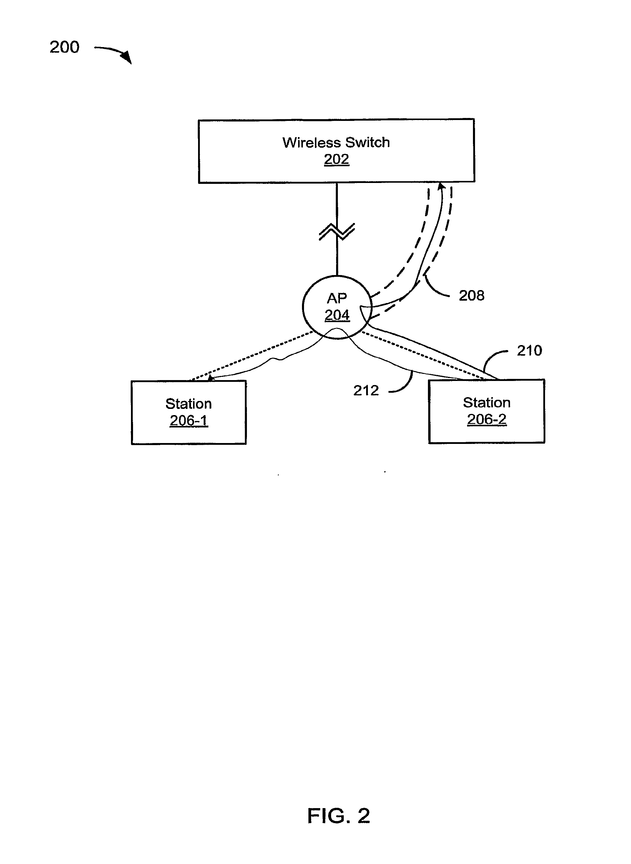
[0031] FIG. 2 depicts an example of a AP-local dynamic switching system 200. The system 200 includes a wireless switch 202, an AP 204 coupled to the switch 202, and two stations 206-1 and 206-2 (referred to collectively as wireless stations 206) wirelessly coupled to the AP 204. In an illustrative embodiment, the switch 202 provides the AP 204 with data in the form of an SSR, which may include various data about the wireless stations 206 (or, more generally, about wireless stations coupled to the switch 202 through the AP 204). The SSR may be any data structure that includes data sufficient to facilitate native switching at the AP 204 or switching at the wireless switch 202. The AP 204 decides whether to natively switch using, by way of example but not limitation, SSID, the class of data associated with the message, a VLAN associated with the station sending the message, authentication data associated with the user of the station sending the message, or some other factor.
[0032] In an illustrative embodiment, the wireless switch 202 knows that the AP 204 is to perform local switching and to which VLANs (if applicable) the AP is connected. However, this is not an absolute requirement.
[0033] In an illustrative embodiment, the AP 204 is a layer 2 switch. In an illustrative embodiment, the AP 204 is coupled to the wireless switch 202 via a tunnel 208. Thus, a message can be tunneled to the wireless switch 202 for layer 2 switching at the wireless switch 202. It should be noted that it may be difficult to support multiple layer 3 protocols. So, by keeping the switching at layer 2, the system 200 need not have a specific layer 3 protocol (e.g., IP). Moreover, if you have a layer 3 backbone with policy in the routers, switching may defeat the policy. Advantageously, layer 2 switching at least reduces or eliminates these problems.
[0034] Since the AP 204 is a switching device, in an illustrative embodiment, the wireless switch 202 does not need to perform packet replication for multicast. Hence, a single multicast packet is transmitted from the wireless switch 202 to the AP 204 where it is replicated by the AP 204 as needed.
[0035] In the example of FIG. 2, the station 206-2 sends messages 210, 212 to the AP 204. The AP 204 treats the messages differently according to data available to the AP 204. In the example of FIG. 2, the AP 204 sends the message 210 to the switch 202 via the tunnel 208. In the example of FIG. 2, the AP 204 performs AP-local switching on the message 212 and sends the message 212 to the station 206-1. It should be noted that the message 210 could be switched at the switch 202 and sent to the station 206-1. Some examples of the various factors that could be considered when the AP 204 determines whether to switch locally or at the switch 202 (e.g., by tunneling) are explored by way of example but not limitation in the FIGS. 3A to 3D.
[0036] FIG. 3A depicts an example of a system 300A performing AP-local dynamic switching per SSID. The system 300A includes an AP 302 and stations 304-1 to 304-3 (referred to collectively as the stations 304). For illustrative purposes only, the AP 302 includes two virtual APs (VAPs) 306-1 and 306-2 (referred to collectively as VAPs 306). As one of skill in the relevant arts would know, an AP can broadcast or otherwise handle multiple SSIDs. If the AP broadcasts or otherwise handles more than one SSID, the AP may be logically treated as multiple APs; each of the logical APs, associated with respective SSIDs, may be referred to as a VAP. In the example of FIG. 3A, the AP 302 switches traffic through VAP 306-1 locally, if possible, and passes traffic through VAP 306-2 upstream for upstream switching. It may be noted that, in a non-limiting embodiment, the AP 302 may perform AP-local dynamic switching per SSID, even if the AP 302 handles a single SSID; the determination is still dynamic even if only one outcome is possible.
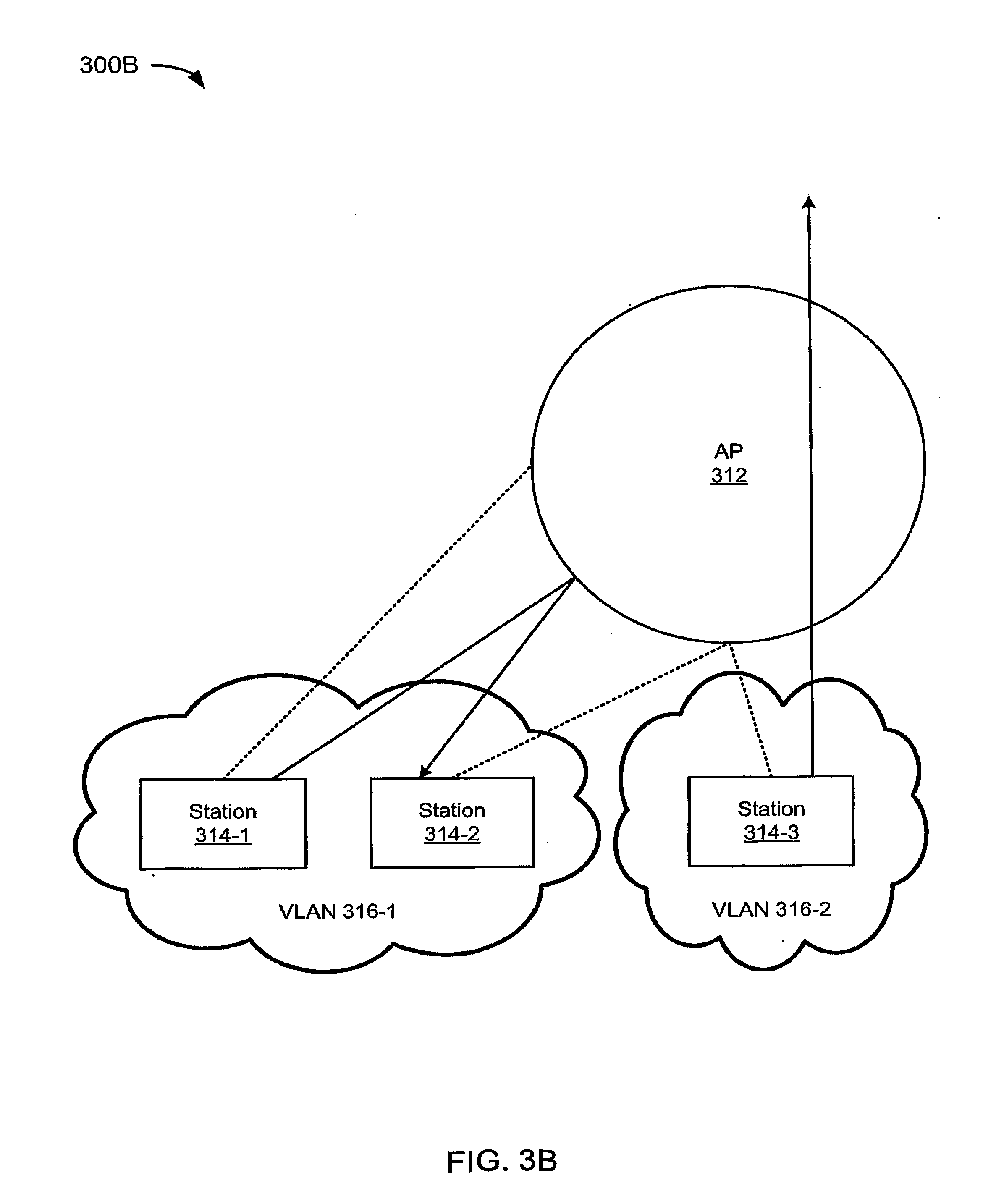
[0037] FIG. 3B depicts an example of a system 300B performing AP-local dynamic switching per VLAN. The system 300B includes an AP 312 and stations 314-1 to 314-3 (referred to collectively as the stations 314). The stations are divided into VLANs 316-1 and 316-2 (referred to collectively as the VLANs 316). For illustrative purposes only, the stations 314-1 and 314-2 are part of the VLAN 316-1 and the station 314-3 is part of the VLAN 316-2. In the example of FIG. 3B, the AP 312 switches traffic from VLAN 316-1 locally, if possible, and passes traffic from VLAN 316-2 upstream for upstream switching.
[0038] FIG. 3C depicts an example of a system 300C performing AP-local dynamic switching per class. The system 300C includes an AP 322 and stations 324-1 to 324-2 (referred to collectively as the stations 324). For illustrative purposes only, the station 324-1 sends data traffic 326 and voice traffic 328 to the station 324-2. In the example of FIG. 3C, the AP 322 switches voice traffic 328 locally, if possible, and passes data traffic 326 upstream for upstream switching. Advantageously, this may enable faster transmission times for voice traffic, which tends to be more time-sensitive than data traffic, while maintaining centralized control of data traffic.
[0039] FIG. 3D depicts an example of a system 300D performing AP-local dynamic switching per user. The system 300D includes an AP 332 and stations 334-1 to 334-2 (referred to collectively as the stations 334). Each of the stations 334 has a respective associated user 336-1 to 336-3 (referred to collectively as the users 336). The users 336 and an AAA engine 338 are depicted for illustrative purposes only, to represent AP-local dynamic switching based on user authentication (e.g., AAA-driven switching). In the example of FIG. 3D, the AP 332 switches traffic from the station 334-1 locally, if possible, because the user 336-1 is allowed to do AP-local switching. However, the AP 332 passes traffic from the station 334-3 upstream for upstream switching because the user 336-3 is not allowed to do AP-local switching. Advantageously, this may enable faster transmission times for certain users, while maintaining centralized control of other users. By way of example but not limitation, the users allowed to do AP-local switching could be employees, while those not allowed to do AP-local switching could be guests. As another example, the users allowed to do AP-local switching could be employees of a first company, while those not allowed to do AP-local switching could be employees of a second company where the first company has superior (or at least different access rights.
[0040] The examples of FIGS. 3A to 3D are intended to provide only a subset of the possible techniques for implementing AP-local dynamic switching. The techniques, whether illustrated in FIGS. 3A to 3D or not, could be used alone or in combination with other techniques, whether illustrated in FIGS. 3A to 3D or not.
[0041] FIG. 4 depicts an example of an AP 400 capable of AP-local dynamic switching. The AP 400 includes a processor 402, an optional Ethernet interface 404, a radio 406, a dynamic switching module 408, and a station switching record (SSR) database 410 coupled together via a bus 412. It may be noted that the various components could be coupled via some means other than the bus 412 without deviating from the scope of the teachings provided herein. The Ethernet interface 404 is optional because, for example, the AP 400 does not use Ethernet, the AP is a UAP that does not have a wired interface, or for some other reason. The radio may be an 802.11 radio, or some other wireless radio.
[0042] In an illustrative embodiment, the dynamic switching module 408 is implemented in a computer-readable medium, such as non-volatile storage and/or memory. The SSR database 410 is also implemented in a computer-readable medium, such as non-volatile storage and/or memory. In operation, portions of the dynamic switching module 408 may be loaded from non-volatile storage into memory, and executed by the processor 402. In an alternative embodiment, the dynamic switching module 408 may have a dedicated processor (not shown). Whether the processor is shared or dedicated, the dynamic switching module 408 and the processor may be referred to collectively as a dynamic switching engine.
[0043] In the example of FIG. 4, in operation, the AP 400 receives from an upstream switch an SSR associated with a downstream station. The SSR is stored in the SSR database 410. The downstream station may be operationally connected to the AP 400 through a wireless link, either directly or indirectly through intervening nodes of a wireless mesh. The dynamic switching engine uses the SSR to determine whether to perform AP-local switching for traffic received from the downstream station at the AP 400, or to send the traffic upstream toward the upstream switch.
[0044] FIG. 5 depicts a flowchart 500 of an example of a method for AP-local dynamic switching. In the example of FIG. 5, the flowchart 500 starts at optional module 502 where data associated with a wireless station is received. The data may be received at, for example, an AP. The module 502 is optional because instead (or in addition), it may be possible to use data associated with traffic to make determinations regarding whether to AP-locally switch the traffic, as is described shortly.
[0045] In the example of FIG. 5, the flowchart 500 continues to module 504 where Layer 2 traffic is received from the wireless station. Advantageously, since the traffic is Layer 2, the system may operate using any Layer 3 protocols (e.g., IP), or even multiple Layer 3 protocols.
[0046] In the example of FIG. 5, the flowchart 500 continues to decision point 506 where it is determined whether to Layer 2 switch the traffic locally. The determination as to whether to switch the traffic locally may be made using data associated with the wireless station (see, e.g., module 502 or data associated with the traffic itself. For example, the wireless station may be authorized for AP-local switching because the wireless station is associated with a particular VLAN. As a second example, the traffic may have a relatively high priority, such as voice traffic often has. If the traffic has a relatively high priority, the determination may be made to switch locally to get the traffic to its destination more quickly. It may be noted that in the second example, the module 502 is optional.
[0047] In the example of FIG. 5, if it is determined that the traffic is to be Layer 2 switched locally (506-Y), the flowchart 500 continues to module 508 where the traffic is Layer 2 switched locally, and to module 510 where the traffic is sent toward its destination. Having switched and sent the traffic, the flowchart 500 ends.
[0048] In the example of FIG. 5, if it is determined that the traffic is not to be Layer 2 switched locally (506-N), the flowchart 500 continues to module 512 where the traffic is Layer 2 tunneled upstream. Presumably, the traffic is switched further upstream. Having Layer 2 tunneled traffic upstream that is not to be switched locally, the flowchart 500 ends.
[0049] As used herein, an AP may refer to a standard (tethered) AP or to a UAP. Where a distinction should be drawn, an AP may be referred to as a "(tethered) AP" or a "UAP," as appropriate. As used herein, the term "embodiment" means an embodiment that serves to illustrate by way of example but not limitation.
[0050] Although the subject matter has been described in language specific to structural features and/or methodological acts, it is to be understood that the subject matter defined in the appended claims is not necessarily limited to the specific features or acts described above. Rather, the specific features and acts described above are disclosed as example forms of implementing the claims.
* * * * *
D00000
D00001
D00002
D00003
D00004
D00005
D00006
D00007
D00008
XML
uspto.report is an independent third-party trademark research tool that is not affiliated, endorsed, or sponsored by the United States Patent and Trademark Office (USPTO) or any other governmental organization. The information provided by uspto.report is based on publicly available data at the time of writing and is intended for informational purposes only.
While we strive to provide accurate and up-to-date information, we do not guarantee the accuracy, completeness, reliability, or suitability of the information displayed on this site. The use of this site is at your own risk. Any reliance you place on such information is therefore strictly at your own risk.
All official trademark data, including owner information, should be verified by visiting the official USPTO website at www.uspto.gov. This site is not intended to replace professional legal advice and should not be used as a substitute for consulting with a legal professional who is knowledgeable about trademark law.