Method And Apparatus For 3-dimensional Vision And Inspection Of Ball And Like Protrusions Of Electronic Components
Puah; Yong Joo ; et al.
U.S. patent application number 12/305835 was filed with the patent office on 2010-12-30 for method and apparatus for 3-dimensional vision and inspection of ball and like protrusions of electronic components. Invention is credited to Yong Joo Puah, Hak Wee Tang, Soon Poo Teo.
| Application Number | 20100328435 12/305835 |
| Document ID | / |
| Family ID | 38833695 |
| Filed Date | 2010-12-30 |


View All Diagrams
| United States Patent Application | 20100328435 |
| Kind Code | A1 |
| Puah; Yong Joo ; et al. | December 30, 2010 |
METHOD AND APPARATUS FOR 3-DIMENSIONAL VISION AND INSPECTION OF BALL AND LIKE PROTRUSIONS OF ELECTRONIC COMPONENTS
Abstract
A method for 3-dimensional vision inspection of objects, such as microelectronic components, which have protrusions as features to be inspected, such as input/output contact balls, is disclosed. The method comprising the steps of determining interior and exterior parameters of a pair of cameras, forming a rectified coordinate system from the parameters of both cameras determined above with a relative pose of second image capturing means with respect to the first image capturing means. A pair of images of the object having a plurality of co-planar protrusions on one surface are captured by the cameras system wherein image coordinates of the images are transformed into coordinates of the rectified coordinate system. Conjugate points of each protrusion are then determined for the measurement of its co-planarity and height. Various configurations of the apparatus for capturing the images and processing the image data are also disclosed.
| Inventors: | Puah; Yong Joo; (Singapore, SG) ; Tang; Hak Wee; (Singapore, SG) ; Teo; Soon Poo; (Singapore, SG) |
| Correspondence Address: |
    OHLANDT, GREELEY, RUGGIERO & PERLE, LLP
    ONE LANDMARK SQUARE, 10TH FLOOR
    STAMFORD
    CT
    06901
    US
|
| Family ID: | 38833695 |
| Appl. No.: | 12/305835 |
| Filed: | March 29, 2007 |
| PCT Filed: | March 29, 2007 |
| PCT NO: | PCT/SG2007/000088 |
| 371 Date: | December 19, 2008 |
| Current U.S. Class: | 348/47 ; 348/E13.074 |
| Current CPC Class: | H05K 13/0818 20180801; G01N 21/8806 20130101; G06T 2207/10152 20130101; G06T 2207/30148 20130101; G06T 7/0004 20130101; G06T 7/70 20170101; H04N 13/246 20180501; G06T 2207/30152 20130101; G06T 2200/04 20130101; G06T 2207/10012 20130101; G06T 7/593 20170101; G01N 21/951 20130101; G06T 7/0006 20130101; G01N 21/95684 20130101; G06T 2207/30244 20130101; H04N 13/239 20180501; G06T 7/80 20170101; H04N 13/243 20180501; H04N 13/254 20180501; G01B 11/0608 20130101 |
| Class at Publication: | 348/47 ; 348/E13.074 |
| International Class: | H04N 13/02 20060101 H04N013/02 |
Foreign Application Data
| Date | Code | Application Number |
|---|---|---|
| Jun 21, 2006 | SG | 200604252-7 |
Claims
1. A method for 3-dimensional vision inspection of objects, including microelectronic components, having protrusions as features to be inspected, wherein said protrusions having surfaces that are non-planar and/or curvatures, said method comprising the steps of: (a) providing at least a pair of image capturing means with similar interior parameters arranged in a stereovision configuration; (b) calibrating each of said image capturing means to determine the interior and exterior parameters of said image capturing means; (c) forming a rectified coordinate system from the parameters of both image capturing means determined above with a relative pose of second image capturing means with respect to the first image capturing means; (d) capturing an image of an object to be inspected using each of said image-capturing means, wherein said object having a plurality of co-planar protrusions and said image captured is of at least one surface curvature of each of said protrusion; (e) rectifying coordinates of each image to produce a pair of rectified images in the said rectified coordinate system; (f) determining a conjugate point for the centre of each protrusion on each of the pair of images captured; and (g) measuring the distance of each protrusion from at least one of the image capturing means within the rectified coordinate system and the co-planarity of the protrusions.
2. A method for 3-dimensional vision according to claim 1 wherein step (g) measuring the distance of each protrusion from at least one of the image capturing means and calculation of co-planarity of the protrusions comprising: determining from the rectified coordinates using established mathematical functions the distance of each of the protrusions from at least one of the image capturing means.
3. A method for 3-dimensional vision according to claim 1 further including the step of: (h) calculating the co-planarity of the protrusions based on the distance of each protrusion to form a seating plane using standard best-fit plane algorithm.
4. A method for 3-dimensional vision according to claim 3 further including the step of: (i) calculating the height of the protrusions wherein: the substrate plane is determined with reference to the rectified coordinates; and perpendicular distance of protrusion to the substrate plane is taken as the protrusion height.
5. A method for 3-dimensional vision according to claim 4 wherein the protrusion height is calculated as follows: (i) approximating with a second plane, in addition to the first seating plane, that is constructed with protrusions having good co-planarity values; (ii) shifting said second plane by the amount of nominal protrusion height to form the substrate plane; and (iii) taking the height of the protrusion as the perpendicular distance of said protrusion to the substrate plane.
6. A method for 3-dimensional vision according to claim 1 wherein the calibration in step (b) is determined in relation to the measurement plane.
7. A method according to claim 6 wherein the measurement plane is provided in the form of a calibration grid.
8. A method for 3-dimensional vision according to claim 1 wherein the conjugate points of each protrusion being determined in step (f) includes (i) locating in each rectified image, the edges of the object to draw up the boundaries of the object; and (ii) performing standard blob analysis to locate the gross position of each protrusion.
9. A method for 3-dimensional vision according to claim 1 wherein step (f) further includes (iii) projecting two edge-detecting windows onto each protrusion to locate its top and bottom edges up to sub-pixel accuracy; (iv) projecting a third edge-detecting window from a central vertical position of the protrusion to detect the left edge of the protrusion in right image and the right edge of the protrusion in the left image up to sub-pixel accuracy; and (v) assigning conjugate points to be right and left edges of the protrusion.
10. A method for 3-dimensional vision according to claim 9 wherein step (g) further includes (vi) calculating disparity of the protrusion to be the difference between the positions of the said right and left edges; and (vii) determining the distance of the protrusion from the stereoscopic camera configuration utilizing the disparity and the relative pose computed during calibration.
11. A method for 3-dimensional vision according to any one of the preceding claims wherein the protrusion to be inspected has at least one of a round edge or ball tip, including pins of a pin grid array (PGA) package, balls of ball grid array (BGA), and like microelectronic packages.
12. An apparatus for 3-dimensional vision inspection of non-planar objects, including microelectronic components, wherein, for calibration and/or measurement purposes, said apparatus comprising: (a) at least a pair of image capturing devices with similar interior parameters arranged in a stereovision configuration; (b) a pair of reflective surfaces for reflecting an image of an object to be inspected to be captured by each of said image-capturing means; and (c) means for mounting said object to be inspected to enable said object's image to be so reflected and so captured; wherein said object has a plurality of co-planar protrusions on at least one surface or substrate.
13. An apparatus for 3-dimensional vision inspection according to claim 12 wherein the object to be inspected is placed within a ring of light source and is illuminated thereby.
14. An apparatus for 3-dimensional vision inspection according to claim 13 wherein the light source comprises a plurality of light-emitting diodes (LED) with their light beam positioned at about an inclination of 25.degree. towards the object to be inspected.
15. An apparatus for 3-dimensional vision inspection according to claim 14 wherein a background light source is further provided.
16. An apparatus for 3-dimensional vision inspection according to claim 12 wherein the image capturing device comprises a camera and a frame grabber.
17. An apparatus for 3-dimensional vision inspection according to claim 16 wherein the frame grabbers are connected to a data processing means via a high-speed data transfer bus including an IEEE-1394 bus (also known as "Firewire").
18. An apparatus for 3-dimensional vision inspection according to claim 17 wherein the data processing means is a computer capable of running at least a program for calibrating, rectifying and processing captured images.
19. An apparatus for 3-dimensional vision inspection according to any one of claims 12 to 18 further including a third image capturing device for another imaging process.
20. An apparatus for 3-dimensional vision inspection according to claim 19 wherein the third image capturing device is placed in between the pair of first two image capturing devices and is configured for inspecting another type of feature of the object, or another type of object.
21. An apparatus for 3-dimensional vision inspection according to claim 12 wherein a calibration reticle for having its image captured for calibration process is provided removably mounted.
22. An apparatus for 3-dimensional vision inspection according to claim 12 wherein the reflective surfaces are positioned at an inclination of about 22.5.degree. from parallel axis towards the object to be inspected so that images of said object are reflected at parallel into the image capturing devices.
23. An object which has been inspected according any one of the methods of claims 1-11 or with an apparatus according to any one of claims 12-22.
24. An object according to claim 23 which is any one of a microelectronic pin ball array (PGA) and ball grid array (BGA) packages.
25. A facility wherein an apparatus according to any one of claims 12 to 22 is installed.
Description
TECHNICAL FIELD
[0001] This invention relates to a method for inspecting objects in 3-dimensional vision, including inspecting electronic components which features' texture may require inspection that is detailed to a sub-pixel scale. An apparatus implementing such method is also disclosed.
BACKGROUND OF THE INVENTION
[0002] In a high-precision manufacturing environment where high volume of precision small objects are made, such as microelectronics fabrication and packaging of components, it is often necessary for each of the completed object such as a microelectronic package to be inspected for quality control purposes. Due to the large volume, such inspection has to be automated and due to the inspection involving examining specific critical feature of the package, such as co-planarity of the contact elements in the form of balls in a ball grid array (BGA) device, 3-dimensional vision is required.
[0003] Some vision systems uses a single axial camera with a plurality of reflective surfaces to pick up different views of the object to be integrated in a single image such as that disclosed in U.S. Pat. No. 6,055,054 (Beaty, et al.), WO01/04567 and US-2002/37098. Normally, an algorithm in the form of software is used to process the different reflected views of the object to be integrated into a single image to be inspected.
[0004] 3-dimensional view in true stereoscopic vision can only be achieved by having at least 2 cameras such as that disclosed in U.S. Pat. No. 6,778,282 (ICOS Vision Systems), U.S. Pat. No. 6,064,756 and U.S. Pat. No. 6,064,757 (both by Beaty, of al.). These vision systems generally employ a first camera to capture an incident view of the object and a second camera to take a second view from another angle whether directly or indirectly via reflective surfaces.
[0005] Our present method for stereoscopic vision of inspecting objects makes use of certain functions of Halcon.TM. Imaging Processing Library (version 7.1) by MVTec Software GmbH of Munchen, Germany. Some of Halcon.TM. references are available from its website at http://www.mvtec.com/download/documentation/documentation.html, including its user manual on 3-dimensional vision system entitled Machine Vision in World Coordinates available at http://www.mvtec.com/download/documentation/pdf-7.1/3DMachineVision.pdf which, along with other relevant Halcon.TM. publications, are incorporated herein by reference.
[0006] The stereoscopic camera system comprises two cameras trained on the same object from different positions. With a pair of cameras, a pair of image points from the projection of a point on the object may be captured. The image points are often referred to as "conjugate points" or "homologous points". By making use of interior parameters of both cameras and the relative pose of the second camera in respect of the first camera obtained during a prior calibration process, the distance of the said object point from the stereoscopic camera system can be determined.
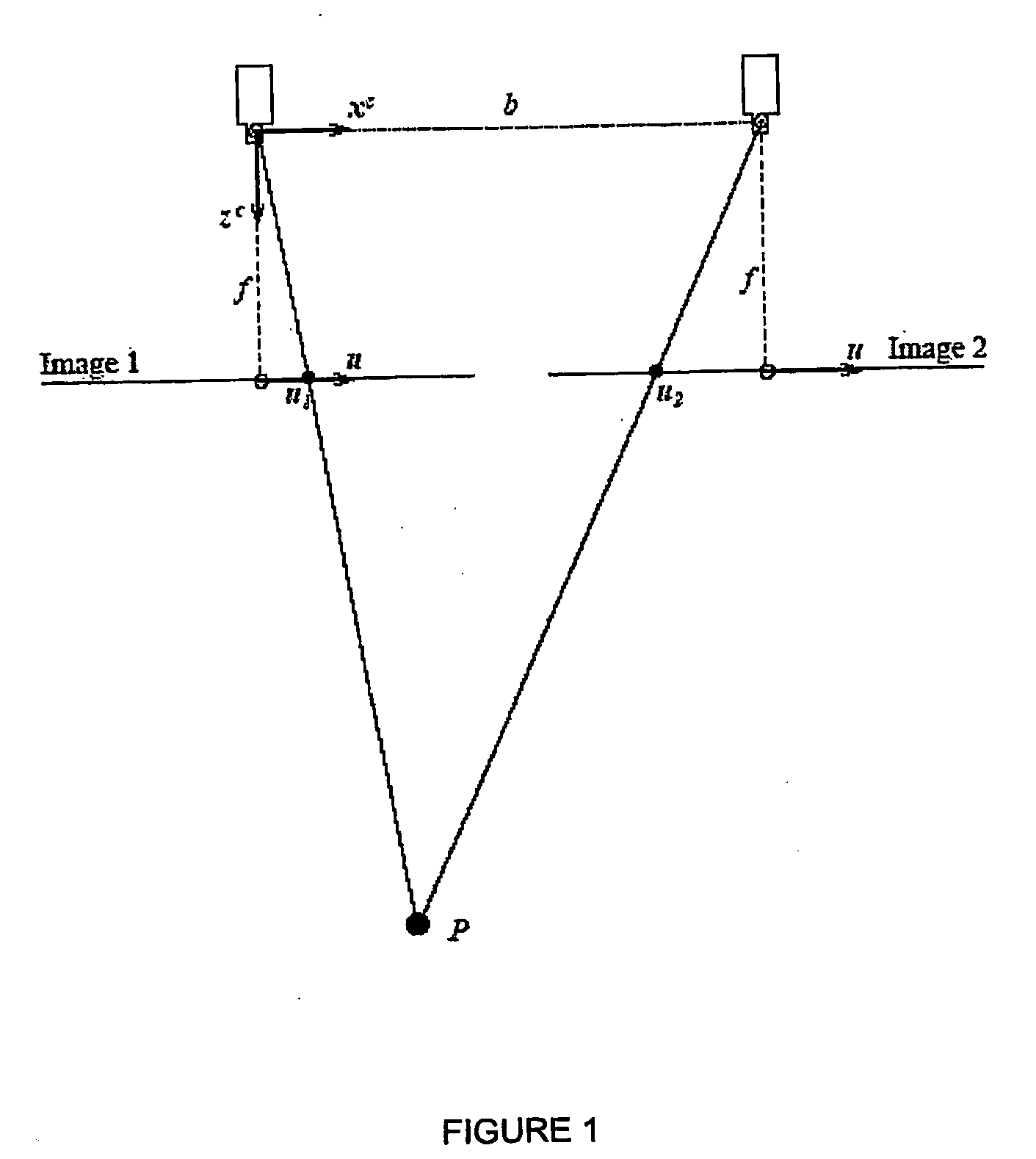
[0007] A simplified configuration of two parallel-trained single-dimension cameras with identical interior parameters may be shown in FIG. 1 (Prior Art). The basis, i.e. the straight line connecting the two optical centres of the two cameras, may be assumed to be coincident with the x-axis of the first camera. Then, the image plane coordinates of the projections of the point P (x.sup.c, z.sup.c) may be expressed into two images, u.sub.1 and u.sub.2, as follows:
u 1 = f x c z c ##EQU00001## u 2 = f x c - b z c ##EQU00001.2##
where f is the focal length and b the length of the basis. The difference between the two image locations of the conjugate points is called the disparity d, which may be calculated as follows:
d = ( u 1 - u 2 ) = f b z c ##EQU00002##
[0008] Given the camera parameters and the image coordinates of two conjugate points, the z.sup.c coordinate of the corresponding object point P, i.e. the distance from the stereo camera system, can be computed from the following equation:
z c = f b d ##EQU00003##
[0009] It should be noted that the interior camera parameters of both cameras and the relative pose of the second camera in relation to the first camera are necessary to determine the distance of P from the stereo camera system.
[0010] Two basic operations that need to be solved for conventional stereo vision are:
[0011] Step 1--Determination of the interior parameters of both cameras and the relative pose between them during initial set-up, and
[0012] Step 2--Determination of a pair of conjugate points for each object point of interest in stereo image pair captured during inspection to compute the said object points' distances from the stereoscopic camera system.
[0013] The first operation involves calibration of the stereoscopic camera system whereby a calibration plate is placed such that it lies completely within both the field of view of the stereo image pair. With Halcon.TM. Imaging Processing Library, the calibration of both images may be carried out simultaneously with the operator termed as "binocular calibration" [see section 7.3, page 94 of Machine Vision in World Coordinates, Edition 2, Halcon.TM. 7.1.0, published July 2005]. After a successful calibration, a virtual stereoscopic camera system called rectified stereoscopic camera system, of which the rectified coordinate system is with respect to 1.sup.st camera, will be constructed.
[0014] As the accuracy of the 3-dimensional image representation is influenced by the manner in which the cameras are placed, it is important that neither the interior camera parameters (e.g., the focal length) nor the relative pose (e.g., the distance and orientation between the two cameras) of the two cameras changes during the calibration process or between the calibration process, as well as during the ensuing application of the calibrated stereo camera system. It is therefore advisable to mount the two cameras on a stable platform.
[0015] The second operation involves what is called "stereo matching process", which in Halcon.TM. processing involves invoking the operators "binocular disparity" or "binocular distance" [see section 7.4, page 97, op. cit.]which process the necessary calculations to obtain world coordinates from the stereo images. In Halcon.TM. processing, two image points from a stereo image pair captured from the same object point are referred to as conjugate points. From the principle of stereovision, the difference between image locations of the conjugate points, which is called the "disparity", can be used to compute the distance of an object point from the rectified stereoscopic camera system.
[0016] The Halcon.TM. Library provides individual functions to compute disparity or distance of the entire overlapping region of the stereo image pair. These functions must first carry out matching operation to establish conjugate points for all image points within the overlapping region of stereo image pair before disparity or distance profile of the region can be computed. The stereo image pair must first be rectified, based on information gathered from calibration, to align their overall Y image coordinate. Thus the ensuing matching process is mainly to find out the difference of conjugate points in X image coordinate. There are 3 different methods, namely "summed absolute difference", "summed squared differences" and "normalized cross correlation", available for the matching function and all 3 are based on comparison of gray-level pattern within a small matching window. To obtain accurate results, the object's surface must have enough textural information to be captured.
[0017] Unfortunately, this approach is not useful when determining the distance to a small feature having varying surface curvature (hence varying distance) such as a contact solder ball tip of a ball grid array semiconductor package. Using Halcon.TM. matching methods would be cumbersome and inaccurate for the purpose of determining the distance to the centre point of each ball or ball-like protrusion's curved surface as ball surface is void of textural features and is therefore not suitable for Halcon.TM. matching methods.
[0018] Nevertheless, Halcon.TM. methodology also provides functions to compute distance from disparity of conjugate points or distance from the conjugate points directly whereby the conjugate points are to be determined by the user. It should be noted that conjugate points can be taken as rectified coordinates of original image coordinates.
[0019] We have now able to detect the conjugate point of ball tips using our own methodology and yet be able to compute the distance of every ball tip from rectified stereo cameras using Halcon functions. Our process may be more readily understood from the following disclosure.
SUMMARY OF DISCLOSURE
[0020] Our present invention concerns a method for 3-dimensional vision inspection of objects, including microelectronic components having protrusions as features to be inspected, wherein the protrusions have surfaces that are non-planar and/or curvatures such as the tips of pins or balls. In the general embodiment, our method comprises the steps of: [0021] (a) providing at least a pair of image capturing means with similar interior parameters arranged in a stereovision configuration; [0022] (b) calibrating each of said image capturing means to determine the interior and exterior parameters of said image capturing means; [0023] (c) forming a rectified coordinate system from the parameters of both image capturing means determined above with a relative pose of second image capturing means with respect to the first image capturing means; [0024] (d) capturing an image of an object to be inspected using each of said image-capturing means, wherein said object having a plurality of co-planar protrusions and said image captured is of at least one surface curvature of each of said protrusion; [0025] (e) rectifying coordinates of each image to produce a pair of rectified images in the said rectified coordinate system; [0026] (f) determining a conjugate point for the centre of each protrusion on each of the pair of images captured; and [0027] (g) measuring the distance of each protrusion from at least one of the image capturing means within the rectified coordinate system and the co-planarity of the protrusions.
[0028] In one preferred embodiment of our method, the aforesaid step (g) measuring the distance of each protrusion from at least one of the image capturing means and calculation of co-planarity of the protrusions comprises determining from the rectified coordinates using established mathematical functions the distance of each of the protrusions from at least one of the image capturing means.
[0029] Another preferred embodiment of our method further includes step (h), i.e. calculating the co-planarity of the protrusions based on the distance of each protrusion to form a seating plane using standard best-fit plane algorithm. Preferably, our method further still include step (i) i.e. calculating the height of the protrusions wherein the substrate plane is determined with reference to the rectified coordinates; and the perpendicular distance of protrusion to the substrate plane is taken as the protrusion height.
[0030] In one aspect of our invention, the protrusion height is calculated by (i) approximating with a second plane, in addition to the first seating plane, that is constructed with protrusions having good co-planarity values; (ii) shifting said second plane by the amount of nominal protrusion height to form the substrate plane; and (iii) taking the height of the protrusion as the perpendicular distance of said protrusion to the substrate plane.
[0031] In a preferred embodiment, the calibration in step (b) is determined in relation to the measurement plane. Preferably, the measurement plane is provided in the form of a calibration grid.
[0032] In another preferred embodiment, the conjugate points of each protrusion being determined in step (f) includes (i) locating in each rectified image, the edges of the object to draw up the boundaries of the object; and (ii) performing standard blob analysis to locate the gross position of each protrusion. Preferably, step (f) further includes (iii) projecting two edge-detecting windows onto each protrusion to locate its top and bottom edges up to sub-pixel accuracy; (iv) projecting a third edge-detecting window from a central vertical position of the protrusion to detect the left edge of the protrusion in right image and the right edge of the protrusion in the left image up to sub-pixel accuracy; and (v) assigning conjugate points to be right and left edges of the protrusion.
[0033] In yet another embodiment of our method, step (g) further includes (vi) calculating disparity of the protrusion to be the difference between the positions of the said right and left edges; and (vii) determining the distance of the protrusion from the stereoscopic camera configuration utilizing the disparity and the relative pose computed during calibration.
[0034] Preferably, the protrusion to be inspected in our method has at least one of a round edge or ball tip, including pins of a pin grid array (PGA) package, balls of ball grid array (BGA), and like microelectronic packages.
[0035] In another aspect of our invention, an apparatus is provided for 3-dimensional vision inspection of non-planar objects, including microelectronic components, wherein, for calibration and/or measurement purposes. Our apparatus comprises: [0036] (a) at least a pair of image capturing devices with similar interior parameters arranged in a stereovision configuration; [0037] (b) a pair of reflective surfaces for reflecting an image of an object to be inspected to be captured by each of said image-capturing means; and [0038] (c) means for mounting said object to be inspected to enable said object's image to be so reflected and so captured; [0039] wherein said object has a plurality of co-planar protrusions on at least one surface or substrate.
[0040] Preferably, the object to be inspected is placed within a ring of light source and is illuminated thereby. Preferably still, the light source comprises a plurality of light-emitting diodes (LED) with their light beam positioned at about an inclination of 25.degree. towards the object to be inspected. A background light source may preferably be further provided.
[0041] As a preferred embodiment, the image capturing device comprises a camera and a frame grabber, and the frame grabbers are further preferably connected to a data processing means via a high-speed data transfer bus including an IEEE-1394 bus (also known as "Firewire"). Preferably, the data processing means is a computer capable of running at least a program for calibrating, rectifying and processing captured images.
[0042] In an alternative embodiment, our apparatus may further including a third image capturing device for another imaging process. Preferably, the third image capturing device is placed in between the pair of first two image capturing devices and is configured for inspecting another type of feature of the object, or another type of object.
[0043] In another alternative embodiment, a calibration reticle for having its image captured for calibration process is provided removably mounted.
[0044] The reflective surfaces are preferably positioned at an inclination of about 22.5.degree. from parallel axis towards the object to be inspected so that images of said object are reflected at parallel into the image capturing devices.
[0045] These and other advantages of our invention may be better understood with reference to the accompanying drawings and the detailed description in the following.
LIST OF ACCOMPANYING DRAWINGS
[0046] The present invention will now be described in detail with reference to the accompanying drawings that follows, wherein specific embodiments are described as non-limiting examples or illustrations of the workings of the invention, in which:
[0047] FIG. 1 (Prior Art) shows a simplified configuration of two parallel-trained single-dimension cameras with identical interior parameters employed in a conventional imaging system such as Halcon.TM.;
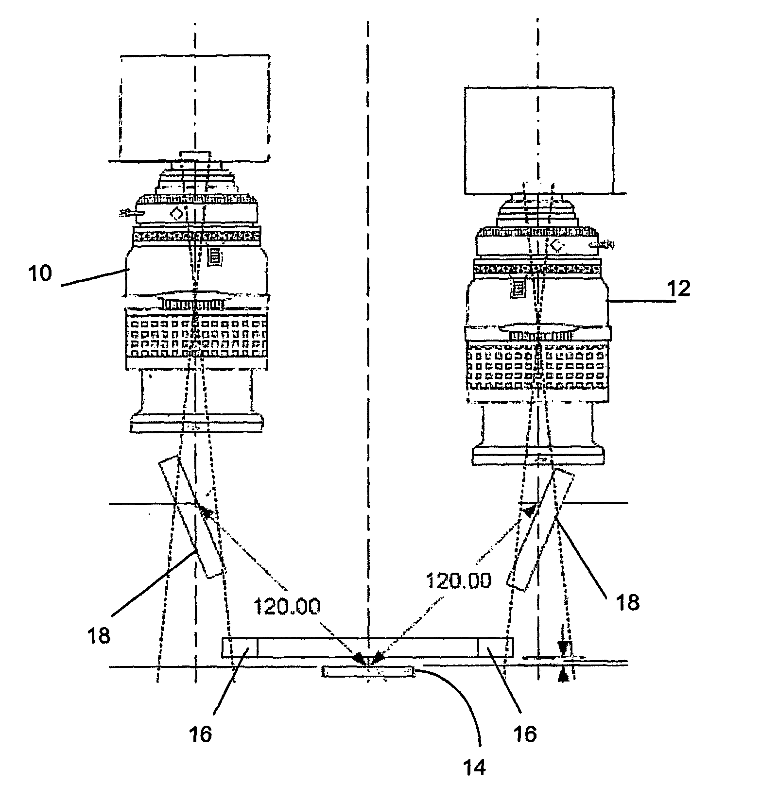
[0048] FIG. 2 shows a basic embodiment of an apparatus in elevation view which enables the method according to our invention;
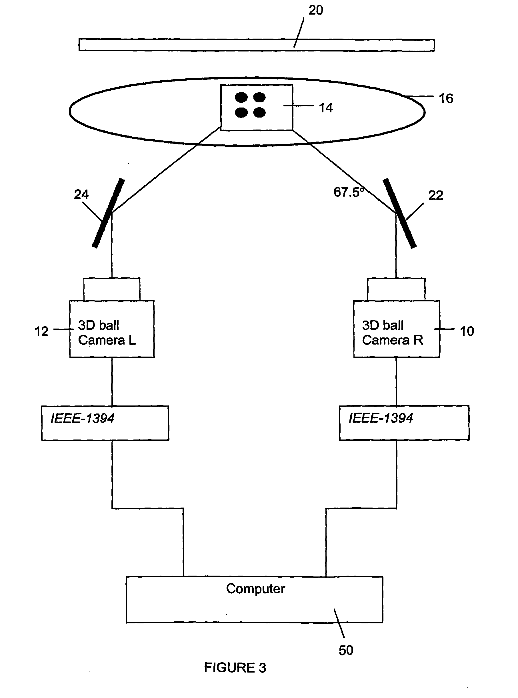
[0049] FIG. 3 shows an embodiment of an apparatus in schematic representation, which includes a back light source for calibration purposes;
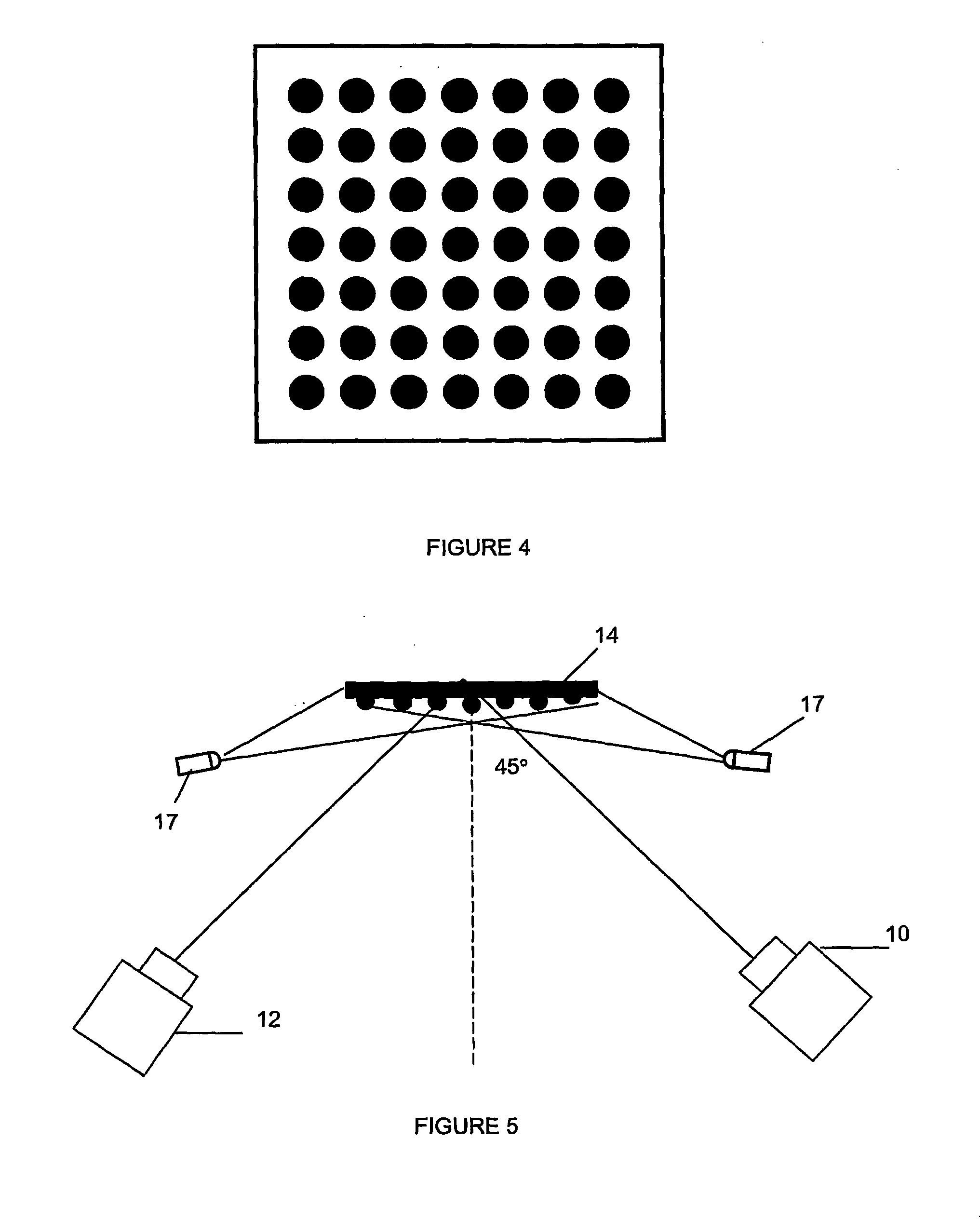
[0050] FIG. 4 shows a calibration grid in form of a square block for use in calibration steps of our invention;
[0051] FIG. 5 shows one embodiment of an apparatus in schematic representation, for inspection purposes;
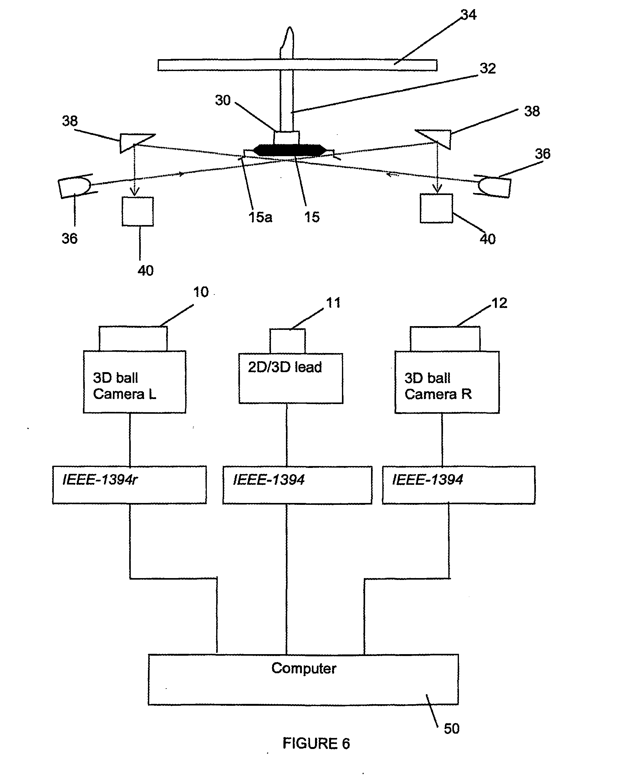
[0052] FIG. 6 shows a second embodiment of an apparatus in schematic representation, which includes a third camera, a light source and mirrors for 2-dimension/3-dimension lead imaging;
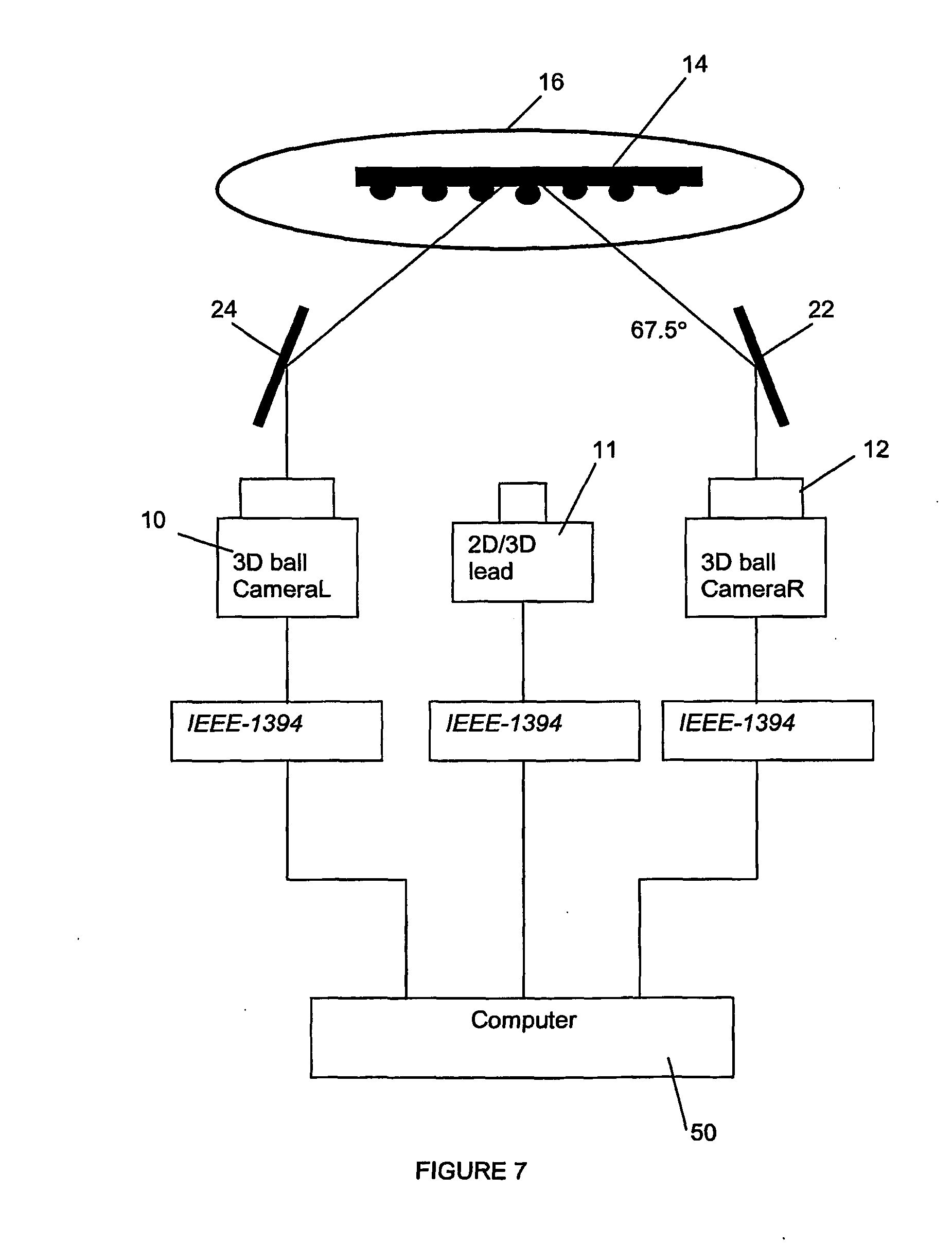
[0053] FIG. 7 shows a third embodiment of an apparatus in schematic representation, for inspection purposes;
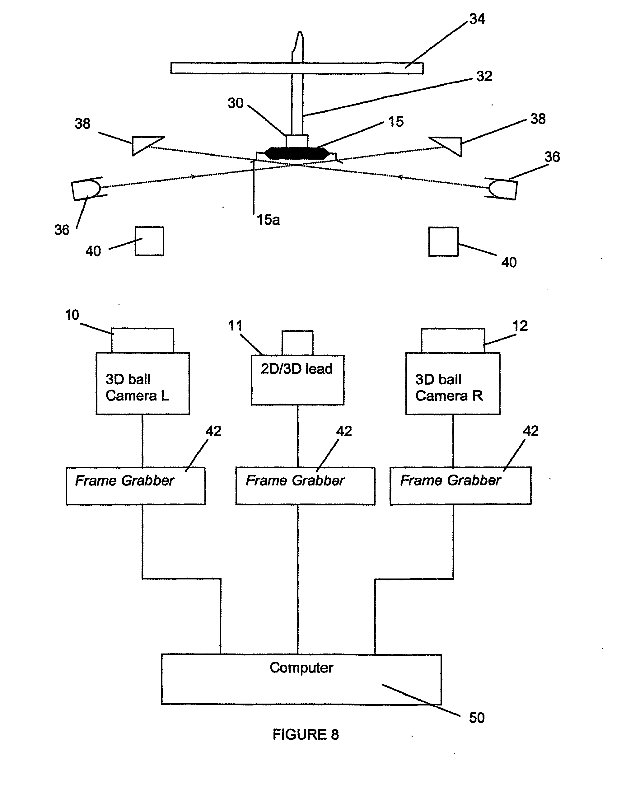
[0054] FIG. 8 shows a fourth embodiment of an apparatus in schematic representation, for inspection purposes; and
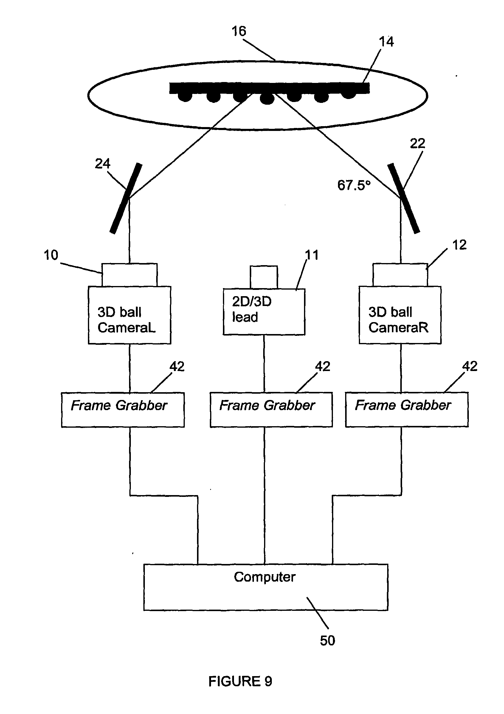
[0055] FIG. 9 shows a fifth embodiment of an apparatus in schematic representation, for inspection purposes.
DETAILED DESCRIPTION OF SPECIFIC EMBODIMENTS
[0056] In the general embodiment of our invention's method may be implemented by a configuration or arrangement of a pair of cameras (10, 12) and other elements such as lighting elements including ring light (16) and reflective surfaces or mirrors (18) as shown in FIG. 2 in an elevation view.
[0057] Our novel method for 3-dimensional vision inspection covers objects (14) such as micro-electronic components having features to be inspected which may include input-output contact points protruding from the package, such as pins and balls of microelectronic packages, including pin grid array (PGA) packages, ball grid array (BGA) and like packages.
[0058] Our method includes the steps of: [0059] (a) providing at least a pair of image capturing means with similar interior parameters arranged in a stereovision configuration; [0060] (b) calibrating each of said image capturing means to determine the interior and exterior parameters of said image capturing means; [0061] (c) forming a rectified coordinate system from the parameters of both image capturing means determined above with a relative pose of second image capturing means with respect to the first image capturing means; [0062] (d) capturing an image of an object to be inspected using each of said image-capturing means, wherein said object having a plurality of co-planar protrusions and said image captured is of at least one surface curvature of each of said protrusion; [0063] (e) rectifying coordinates of each image to produce a pair of rectified images in the said rectified coordinate system; [0064] (f) determining a conjugate point for the centre of each protrusion on each of the pair of images captured; and [0065] (g) measuring the distance of each protrusion from at least one of the image capturing means within the rectified coordinate system and the co-planarity of the protrusions.
[0066] Theoretically after binocular calibration, the distance of everything in front of the stereoscopic camera system can be determined. Even though the relative pose (exterior parameters) derived from binocular calibration has a so-called "measurement plane" in it (world coordinate of z=0), it is not important in 3D measurement. Practically, the distance of all object points falling within focusing range of the stereoscopic camera system can be measured properly. Measurement plane is more relevant for 2D measurement whereby the object is planar and always physically situated on the measurement plane.
[0067] The term "image capturing means" used herein is intended to include both the camera and frame grabber. The camera may cover still camera or video camera. The term "at least a pair" covers two or more camera wherein at least two of the cameras are for stereoscopic vision while the third and subsequent cameras are optional and may or may not relate to inspecting ball-like protrusions from an object to be inspected. "Exterior parameters" includes the parameters defining the spatial arrangement of second camera with respect to the first camera in world coordinate.
[0068] As shown in FIG. 2, the configuration of an apparatus which enables the calibration and/or measurement step outlined above may comprise of: [0069] (a) at least a pair of image capturing devices with similar interior parameters arranged in a stereovision configuration; [0070] (b) a pair of reflective surfaces for reflecting an image of an object to be inspected to be captured by each of said image-capturing means; [0071] (c) means for mounting said object to be inspected to enable said object's image to be so reflected and so captured; [0072] wherein said object has a plurality of co-planar protrusions on at least one surface or substrate.
[0073] In one preferred embodiment of our method, step (g) concerning measuring the distance of each protrusion from at least one of the image capturing means and the calculation of co-planarity of the protrusions may comprise of determining from the rectified coordinates using established mathematical functions the distance of each of the protrusions from at least one of the image capturing means.
[0074] Preferably, the method further includes the step of calculating the co-planarity of the protrusions based on the distance of each protrusion to form a seating plane using standard best-fit plane algorithm.
[0075] Our method for 3-dimensional vision as described above may preferably further include the calculation of the height of protrusion by the following steps: [0076] (i) approximating with a second plane, in addition to the first seating plane, that is constructed with protrusions having good co-planarity values; [0077] (ii) shifting said second plane by the amount of nominal protrusion height to form the substrate plane; and [0078] (iii) taking the height of a protrusion as the perpendicular distance of said protrusion to the substrate plane.
[0079] The calibration step (b) above may preferably be determined in relation to a measurement plane which may preferably be provided in the form of a calibration grid.
[0080] The determination of conjugate points of each protrusion of step (f) may preferably include (i) locating in each rectified image, the edges of the object to draw up the boundaries of the object; and (ii) performing standard blob analysis to locate the gross position of each protrusion. Preferably, step (f) further includes (iii) projecting two edge-detecting windows onto each protrusion to locate its top and bottom edges up to sub-pixel accuracy; (iv) projecting a third edge-detecting window from a central vertical position of the protrusion to detect the left edge of the protrusion in right image and the right edge of the protrusion in the left image up to sub-pixel accuracy; and
step (f) may preferably further includes (v) assigning conjugate points to be the right and left edges of the protrusion.
[0081] As another preferred embodiment, step (g) may preferably further includes the steps of (vi) calculating disparity of the protrusion to be the difference between the positions of the said right and left edges; and (vii) determining the distance of the protrusion from the stereoscopic camera configuration utilizing the disparity and the relative pose computed during calibration.
[0082] The measuring of distance of each protrusion of step (g) may preferably include (i) calculating disparity of the protrusion to be the difference between the positions of the conjugate points. (ii) determining the distance of the protrusion from the stereoscopic camera system utilizing the disparity and the relative pose computed during calibration.
[0083] It should be explained here that the term "relative pose" is used in this specification to mean "exterior parameters" of the image capturing means or 3D camera's positions relative to one another as well as to the object to be examined. The "relative pose" term may also be taken to mean "3D poses" employed in Halcon.TM. methodology. In Halcon.TM., 3D poses means representation of a rigid transformation with 6 parameters, i.e. 3 for rotation and 3 for translation (Rot1, Rot2, Rot3, TransX, TransY, TransZ). The principle of poses is that transformation around even an arbitrary axis can still be represented by a sequence of 3 rotations around the X, Y and Z axes of a coordinate system.
[0084] As shown in FIG. 2, the object to be inspected is preferably placed within and is illuminated by a ring of light source. The light source ring comprises a plurality of light-emitting diodes (LED) with their light beam positioned at about an inclination of 25.degree. towards the object to be inspected. Preferably, a background light source is further provided.
[0085] In one preferred embodiment, as shown in FIG. 3, the cameras are connected to a data processing means via a high-speed data transfer bus including an IEEE-1394 bus (also known as "Firewire"). Data processing means in the form of a computer capable of running at least a program for calibrating, rectifying and processing captured images is provided. Reflective surfaces may be provided at an inclination of about 22.5.degree. from parallel axis towards the object to be inspected so that images of said object are reflected at parallel into the image capturing devices.
[0086] For the purpose of calibration in steps (b) and/or (c), a "calibration grid", also called a "calibration reticle", may be provided as a removably mountable block to have its image captured by the stereoscopic camera system for the calibration process. The block is preferably a rectangular board provided with an array of precision dots within a rectangular border, as shown in FIG. 4, may be used. As an exemplary calibration process, 20 positions of the dots may be captured within the field of vision of each of the cameras. At least 10 of these positions may then be selected for the calibration process.
[0087] During the calibration process, the image pairs are read in sequence to obtain the locations of the dots within the border. As the precise spatial relationship among the dots are known, Halcon.TM. functions may be used to compute the interior camera parameters and the spatial relationship between the two cameras. With these information, a virtual stereo camera system called "rectified stereo camera system" in which the "rectified coordinate system" is determined with respect to the first camera, can be established according to the Halcon.TM. method.
[0088] The spatial arrangement of the cameras and lighting means may be varied according to the features of the object to be captured and processed. For example, as shown in FIG. 3, the object (14) which image is to be captured, may be placed within ring light (16) to provide peripheral illumination to the object (14). A backlight (20) may additionally be provided to provide background illumination.
[0089] The images reflected from the object (14) need not be captured directly by the cameras (10, 12). In fact, as the object size is likely to be a small microchip as is the common form factor of microelectronic packages today, it would be difficult to mount the cameras (10, 12) in parallel to capture the images directly. It would be more practical to have the images captured by the cameras (10, 12) indirectly, i.e. via reflective surfaces or mirrors (22, 24) so that the cameras (10, 12) may be placed apart but still parallel to each other. Preferably, the mirrors (22, 24) are placed at about 22.5.degree. inclination from the parallel axis to the object (or 67.5.degree. inclination from the plane or field of vision upon which the object to be captured is placed).
[0090] FIG. 5 shows an alternative arrangement wherein the object to be inspected (14) is still placed within a ring light comprising LED elements (17). In this arrangement, the cameras are positioned at about 45.degree. on each side from the incidental axis of the object (14).
[0091] FIG. 6 shows another alternative embodiment wherein the object to be examined is a leaded microelectronic package (15) wherein is featured with leads (15a) protruding from the sides of the package. The package (15) is shown picked up by a vacuum wand comprising a pick head (30) and pick arm (32). A backlight or reflector (34) may be provided so that the package (15) may be illuminated from the background. Bar lights (36) are shown provided to illuminate the sides of the package (15), particularly at the peripheral parts where the leads protrude from the package body. Reflective surfaces or mirrors (38) may be provided at the same level as the leads to reflect the images to cameras (10, 12). Preferably, the images are transmitted through optical elements (40), including non-linear optical elements, filters, etc. to enhance the image's contrast.
[0092] It is to be noted that a third camera (11) may optionally be provided at the middle or between the two cameras (10, 12) to enable the images from the package's underside be captured as a whole to be compared or rectified against the separate peripheral images of the leads on each side of the package (15). As with the pair of cameras (10, 12), this third camera (11) may be connected via a high-speed data transfer bus such as Firewire connection (or IEEE-1394 bus). Data processing means in the form of a computer (50) running a program for calibrating, rectifying and processing captured images may be optionally provided.
[0093] FIG. 7 shows a modification of the arrangement of FIG. 3 wherein the third camera (11) is similarly provided as an optional configuration. Instead of using high speed date transfer bus and still cameras, video cameras may be used for fast throughput examination of the microelectronic packages or, other objects to be examined, wherein frame grabbers (42) (or other external devices) may be used in line with each of the video cameras so that the video images may be digitized for processing in the computer (50), as shown in FIGS. 8 and 9.
[0094] Certain parallelization processes or parallel processing of images in Halcon.TM. image functions and operators realized by multi-threaded programming and multi-core processing means may be used to speed up processing time. Other third party image processing algorithms, including frame grabber interfaces, may also be used integrally with Halcon.TM. in speeding up certain processes of our novel method described herein. Such modifications, extension or adaptations are not to be considered as departures from the scope of the present invention as defined in the following claims.
* * * * *
References
D00000
D00001
D00002
D00003
D00004
D00005
D00006
D00007
D00008
XML
uspto.report is an independent third-party trademark research tool that is not affiliated, endorsed, or sponsored by the United States Patent and Trademark Office (USPTO) or any other governmental organization. The information provided by uspto.report is based on publicly available data at the time of writing and is intended for informational purposes only.
While we strive to provide accurate and up-to-date information, we do not guarantee the accuracy, completeness, reliability, or suitability of the information displayed on this site. The use of this site is at your own risk. Any reliance you place on such information is therefore strictly at your own risk.
All official trademark data, including owner information, should be verified by visiting the official USPTO website at www.uspto.gov. This site is not intended to replace professional legal advice and should not be used as a substitute for consulting with a legal professional who is knowledgeable about trademark law.