Method For Signal-technology Safeguarding Of Rail Vehicles And Safeguarding Systems Related Thereto
Braband; Jens ; et al.
U.S. patent application number 12/919531 was filed with the patent office on 2010-12-30 for method for signal-technology safeguarding of rail vehicles and safeguarding systems related thereto. This patent application is currently assigned to SIEMENS AKTIENGESELLSCHAFT. Invention is credited to Jens Braband, Bernhard Evers, Stefan Gerken.
| Application Number | 20100327125 12/919531 |
| Document ID | / |
| Family ID | 40651450 |
| Filed Date | 2010-12-30 |

| United States Patent Application | 20100327125 |
| Kind Code | A1 |
| Braband; Jens ; et al. | December 30, 2010 |
METHOD FOR SIGNAL-TECHNOLOGY SAFEGUARDING OF RAIL VEHICLES AND SAFEGUARDING SYSTEMS RELATED THERETO
Abstract
A method and a protection system for signaling protection of rail vehicles connected to at least one central monitoring facility through a data radio system. In order to eliminate cost-intensive and highly complicated protection technology, the vehicles convey instantaneous position data through the data radio system to the monitoring facility. A safety area is defined around each of the vehicles. The safety area depends on a vehicle speed and a measured value scatter of the positional data collection method being used. A warning area surrounds the safety area and the monitoring facility determines movement-defining data through the vehicle-specific position data, safety areas and warning areas. In order to avoid collision-related overlaps of safety zones and to counteract collision-related overlaps of warning areas, the movement-defining data are transmitted to the affected vehicles by way of the data radio system in the event of collision-relevant overlaps.
| Inventors: | Braband; Jens; (Braunschweig, DE) ; Evers; Bernhard; (Braunschweig, DE) ; Gerken; Stefan; (Braunschweig, DE) |
| Correspondence Address: |
    LERNER GREENBERG STEMER LLP
    P O BOX 2480
    HOLLYWOOD
    FL
    33022-2480
    US
|
| Assignee: | SIEMENS AKTIENGESELLSCHAFT Muenchen DE |
| Family ID: | 40651450 |
| Appl. No.: | 12/919531 |
| Filed: | February 23, 2009 |
| PCT Filed: | February 23, 2009 |
| PCT NO: | PCT/EP09/52096 |
| 371 Date: | August 26, 2010 |
| Current U.S. Class: | 246/62 |
| Current CPC Class: | B61L 21/10 20130101; B61L 2205/04 20130101; B61L 23/24 20130101; B61L 25/025 20130101 |
| Class at Publication: | 246/62 |
| International Class: | B61L 25/02 20060101 B61L025/02 |
Foreign Application Data
| Date | Code | Application Number |
|---|---|---|
| Feb 29, 2008 | DE | 10 2008 012 416.8 |
Claims
1-7. (canceled)
8. A method for signaling protection of rail vehicles, the method comprising the following steps: linking the rail vehicles over a data radio system to at least one central monitoring facility; transmitting instantaneous vehicle-specific position data from the rail vehicles over the data radio system to the monitoring facility; defining a safety area around the rail vehicles in dependence on a vehicle speed and a measured value scatter of a position data recording method being used; defining a warning area surrounding the safety area around the rail vehicles; determining movement-defining data in the monitoring facility by using the vehicle-specific position data, the safety areas and the warning areas, to avoid collision-relevant overlaps of safety areas and to counteract collision-relevant overlaps of warning areas; and transmitting the movement-defining data, at least in an event of collision-relevant overlaps, over the data radio system to relevant rail vehicles.
9. The method according to claim 8, which further comprises evaluating the received position data by correlation with track data for collision relevance.
10. The method according to claim 8, which further comprises identifying overlaps which are not collision-relevant by a token method.
11. The method according to claim 8, which further comprises triggering at least one of audible or visual signaling at the vehicle, in an event of collision-relevant overlapping of warning areas.
12. The method according to claim 8, which further comprises triggering forced braking at the vehicle, in an event of collision-relevant overlapping of safety areas.
13. The method according to claim 8, which further comprises determining the position data with a satellite-assisted position-finding system.
14. A protection system for carrying out the method according to claim 8, the system comprising: a device for vehicle-specific position data recording; a transmitting/receiving appliance disposed in a rail vehicle and having a transmitting component connected to the device for vehicle-specific position data recording; a device for determining the safety area around the vehicle as a function of a vehicle speed and a measured value scatter of the device for vehicle-specific position data recording and for determining the warning area surrounding the safety area around the vehicle; and the monitoring facility having a device for determining movement-defining data based on the vehicle-specific position data, the safety areas and the warning areas to avoid collision-relevant overlaps of safety areas and to counteract collision-relevant overlaps of warning areas, and the monitoring facility transmitting the movement-defining data, at least in the event of collision-relevant overlaps, over the data radio system to the relevant rail vehicles.
15. A system for signaling protection of rail vehicles, the system comprising: a device for vehicle-specific position data recording; a transmitting/receiving appliance disposed in the rail vehicle and having a transmitting component connected to said device for vehicle-specific position data recording; a device for determining a safety area around the rail vehicle as a function of a vehicle speed and a measured value scatter of said device for position data recording and for determining a warning area surrounding the safety area around the rail vehicle; a monitoring facility having a device for determining movement-defining data based on the vehicle-specific position data, the safety areas and the warning areas to avoid collision-relevant overlaps of safety areas and to counteract collision-relevant overlaps of warning areas; and a data radio system for transmitting the movement-defining data, at least in an event of collision-relevant overlaps, from said monitoring facility to relevant rail vehicles.
Description
[0001] The invention relates to a method for signaling protection of rail vehicles which are linked via a data radio system to at least one central monitoring facility, and to a protection system for it. Known train protection systems are based on finding the position of the train by means of trackside position-finding devices, for example beacons or axial counting devices. These train protection systems are highly centralized, which means that even very minor changes, for example to the track plan, require considerable adaptation effort. A further disadvantage is that the installation, wiring and maintenance of external elements result in a major financial penalty. Satellite-based methods currently do not offer sufficient precision in order to be used for position finding in the conventional protection method.
[0002] Particularly on single-track lines and branch lines, highly complex track protection technology is normally not used, for cost reasons. Movement permission or permission to continue moving is transmitted by a movement service manager in a control center by radio to the locomotive engineer on the basis of a movement plan and the current track occupancy. Incorrect movement permissions or their misinterpretation by the locomotive engineer can lead to dangerous, collision-relevant situations. It is therefore frequently necessary to reserve major sections of little-used track areas exclusively for individual vehicles, as a result of which only a very low track flow rate can be achieved.
[0003] The invention is based on the object of providing a method for signaling protection of rail vehicles and a protection system for it, which allow technical assistance for identification and avoidance of a risk of collision using simple means, in particular without any track elements for position finding.
[0004] According to the method, the object is achieved in that the vehicles transmit their instantaneous position data via the data radio system to the monitoring facility in that a safety area, which is dependent on a vehicle speed and a measured value scatter of the position data recording method used, and a warning area which surrounds the safety area are in each case defined around the vehicles, and in that the monitoring facility uses the vehicle-specific position data, safety areas and warning areas to determine movement-defining data, such that collision-relevant overlaps of safety areas are avoided, and collision-relevant overlaps of warning areas are counteracted, wherein the movement-defining data is transmitted, at least in the event of collision-relevant overlaps, via the data radio system to the relevant vehicles. According to claim 7, a protection system is used for this purpose, in which a transmitting/receiving appliance is provided in the vehicle, whose transmitting component is connected to a device for position data recording, in which a device for determining a safety area as a function of a vehicle speed and a measured value scatter of the device for position data recording and a warning area, which surrounds the safety area, around the vehicle is provided, and in which the monitoring facility has a device for determining movement-defining data on the basis of the vehicle-specific position data, safety areas and warning areas such that collision-relevant overlaps of safety areas are avoided, and collision-relevant overlaps of warning areas are counteracted, wherein the movement-defining data can be transmitted, at least in the event of collision-relevant overlaps, via the data radio system to the relevant vehicles.
[0005] This makes it possible to achieve an increase in the safety level even without using conventional, costly protection technology. There is no need for any additional decentralized trackside devices as a result of which the investment costs are low, while it is nevertheless possible to achieve a higher safety level.
[0006] The vehicle is completely embedded, that is to say including wagons connected to it, in the safety area, wherein the extent, at least in the direction of travel, must correspond at least to the speed-dependent braking distance. The size of the safety area is also dependent on the measured value scatter, that is to say on the measurement inaccuracy, of the position data recording. It is desirable to ensure that this safety area can never overlap the safety area of another vehicle in a collision-relevant manner. For this purpose, a warning area is placed around the safety area and, if the warning area overlaps the warning area of another vehicle, a counter-reaction is introduced at this stage, if this is actually a collision-relevant overlap.
[0007] In order to make it possible to distinguish between a collision-relevant overlap and an overlap which is not collision-relevant, claim 2 provides that the received position data is evaluated by correlation with track data for collision relevance. Overlaps which are not safety-relevant are possible, in particular, when two vehicles are approaching on parallel tracks or can overtake without meeting. In addition, vehicles which are to be expected at the identified position on the basis of the timetable, and which are waiting for movement permission in the case of single-track sections on an adjacent station track or a bypass track, can thus be identified as not being critical. The monitoring facility can use the points position and the instantaneous position data of the vehicles to assess the danger of overlaps, without any further information, on the basis of the starting position of each vehicle.
[0008] In the case of railway tracks with a low operating density or predominantly single-track operation, it is possible, according to claim 3, for overlaps which are not collision-relevant to be identified by a token method. The token method, which is known per se, ensures that only one vehicle ever moves on the monitored track section, under the complete responsibility of the locomotive engineer, and all other vehicles in the overlapping warning area or, if appropriate, in the overlapping safety area as well, are stationary. In order to allow a worthwhile sequence of vehicle movements in this case, the sequence must be manually controllable, in which case, where necessary, a token can also be handed back again to the central monitoring facility. While the method restricts the movement of the vehicles on a token basis, the locomotive engineer of the moving vehicle is responsible for ensuring that no collision with a stationary vehicle occurs. The safety level which can be achieved in this way corresponds to the previous safety on branch lines.
[0009] Only those overlaps which are identified as collision-relevant indicate an increased potential danger and, according to claim 4, lead to a collision warning if the warning areas overlap, with this being signaled audibly and/or visually to the locomotive engineer. The locomotive engineer has the obligation to comply with measures, for example speed reduction, when implementing the movement-defining data which in this case is transmitted from the monitoring facility via the data radio system.
[0010] If an extreme danger situation occurs, in which not only the warning areas overlap but, in addition, at least one safety area of a vehicle is also involved, forced braking is envisaged according to claim 5.
[0011] The position data, to be determined within the vehicle, is determined with satellite assistance according to the embodiment to be preferred according to claim 6. If the position data information fails, for example when moving through tunnels or as a result of topographically dependent shadowing, the process of determining position data can be continued on the basis of the most recent position and the speed for a projectable time. Alternatively or additionally, it is also possible to use position data determined by an odometer. The relatively wide scatter width of the position-finding data, in particular satellite position-finding data, is used to define the safety area and the warning area, and therefore no longer represents a problem. Since the vehicles are moving objects, the safety area and warning area can be defined individually on a speed-dependent basis for each vehicle. If the speed is not transmitted together with the position-finding data to the central monitoring facility, the maximum permissible vehicle speed applicable on the respective track section can also be used as the basis for defining the safety area and the warning area. Different position-finding accuracy scatter widths occur depending on the position-finding system being used, and these are likewise included in the definition of the warning areas and safety areas. Furthermore, the stability of the data radio transmission should also be taken into account. Because of the use of radio technology, the data link between a vehicle and a monitoring facility can fail at any time. The maximum time for a link failure such as this can additionally be included in the definition of the warning area and safety area.
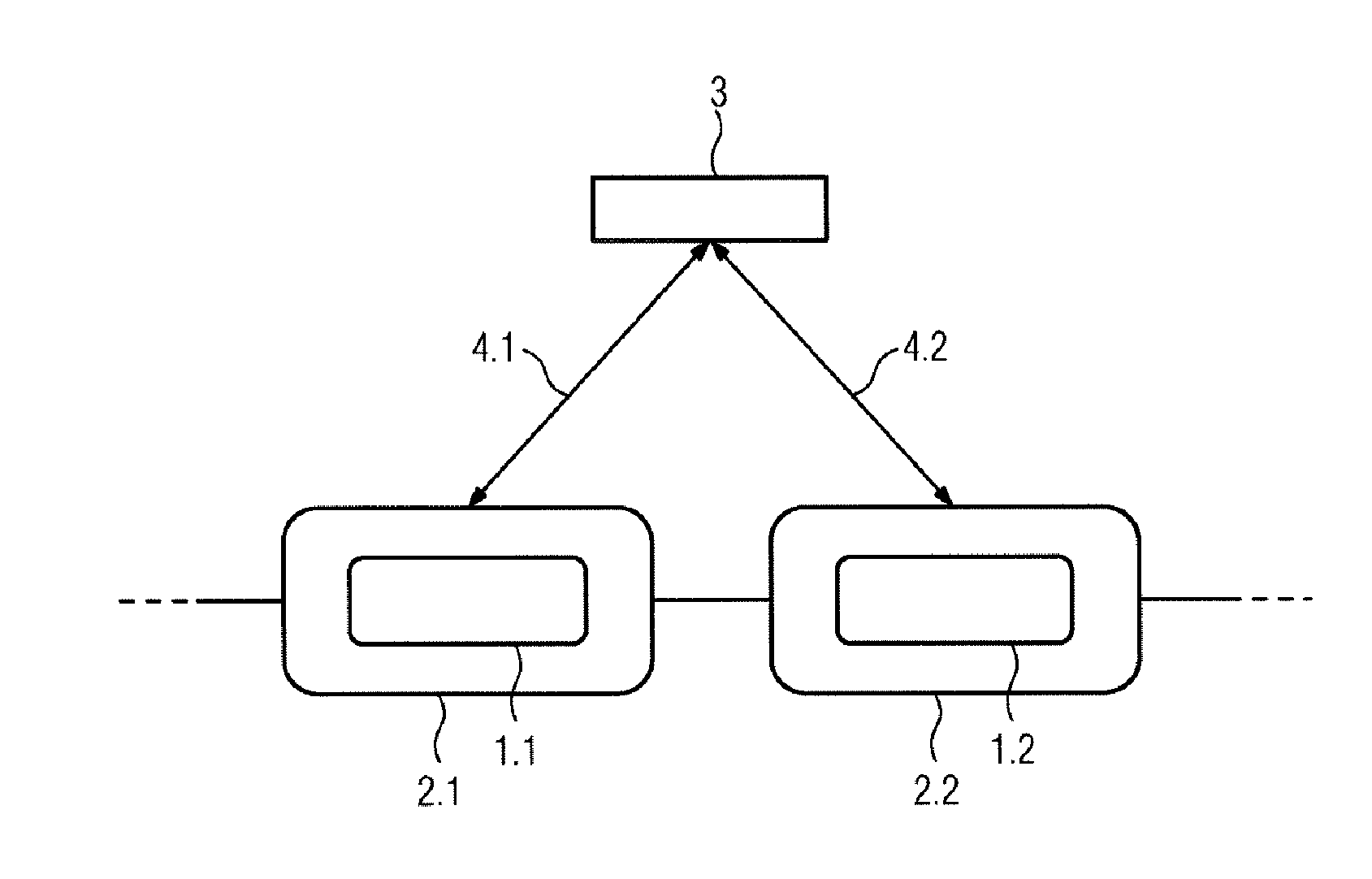
[0012] The invention will be explained in the following text with reference to a FIGURE illustration.
[0013] The single FIGURE shows a safety area 1.1 and 1.2, respectively, and a warning area 2.1 and 2.2, respectively, for two vehicles, interacting with a central monitoring facility 3. The vehicles, which are not illustrated, are completely embedded in the respective safety area 1.1 or 1.2, while the warning area 2.1 or 2.2 completely surrounds the respective safety area 1.1 or 1.2. The vehicles are equipped with satellite position-finding receivers, whose measured value scatter, which can also cover adjacent tracks, governs the extent of the safety area 1.1 or 1.2, and therefore also of the respective warning area 2.1 or 2.2. The vehicles use wireless communication, for example GSM-R, via data radio links 4.1 and 4.2 respectively, for connection to the monitoring facility 3 and continually transmit the position data measured with satellite assistance, and preferably also the current speed, to the monitoring facility 3. The monitoring facility 3 uses the position-finding data, safety areas 1.1 and 1.2 and warning areas 2.1 and 2.2, respectively, to determine whether the warning areas 2.1 and 2.2 overlap and, if yes, whether this overlap is collision-relevant. The latter is the case only if the vehicles are moving on the same route, which is specific to the points position. The points position is known in the monitoring facility 3, as a result of which the monitoring facility 3 is able to identify whether there is actually a collision danger or whether the vehicles are merely moving past one another on adjacent tracks, in which case safety areas 1.1 and 1.2 can also be involved in the overlap. Only in the event of a real collision danger does the monitoring facility 3 transmit warning messages to the vehicles involved, which are then braked on the responsibility of the locomotive engineer himself, or are automatically force-braked by means of an appropriate vehicle appliance. In the end, the described method allows the use of inaccurate vehicle-internal position-finding methods, in particular satellite position-finding, in which case a very high safety level can be achieved even without using conventional, costly track protection technology.
* * * * *
D00000
D00001
XML
uspto.report is an independent third-party trademark research tool that is not affiliated, endorsed, or sponsored by the United States Patent and Trademark Office (USPTO) or any other governmental organization. The information provided by uspto.report is based on publicly available data at the time of writing and is intended for informational purposes only.
While we strive to provide accurate and up-to-date information, we do not guarantee the accuracy, completeness, reliability, or suitability of the information displayed on this site. The use of this site is at your own risk. Any reliance you place on such information is therefore strictly at your own risk.
All official trademark data, including owner information, should be verified by visiting the official USPTO website at www.uspto.gov. This site is not intended to replace professional legal advice and should not be used as a substitute for consulting with a legal professional who is knowledgeable about trademark law.