Packaging Of Confectionery Items
Mohda; Asit ; et al.
U.S. patent application number 12/440061 was filed with the patent office on 2010-12-30 for packaging of confectionery items. This patent application is currently assigned to CADBURY HOLDINGS LIMITED. Invention is credited to Sophie Caron, Robert C. Lindsay, Asit Mohda.
| Application Number | 20100327046 12/440061 |
| Document ID | / |
| Family ID | 37232589 |
| Filed Date | 2010-12-30 |

| United States Patent Application | 20100327046 |
| Kind Code | A1 |
| Mohda; Asit ; et al. | December 30, 2010 |
PACKAGING OF CONFECTIONERY ITEMS
Abstract
Packaging of a stack of confectionery pellets having a longitudinal axis extending through all the pellets in the stack comprises a sheet wrapper that encases the stack. The wrapper is formed into a side wall portion which encircles the stack about the longitudinal axis and two end cap regions, each end cap region enclosing a respective axial end of the stack. A tear guide to assist a user in opening the packaging extends about the axis and is positioned at least partially within one of the end cap regions. The tear guide may be defined by lines of weakness in the wrapper which may be formed by laser etching. A method of packing a stack of confectionery items is also disclosed.
| Inventors: | Mohda; Asit; (Middlesex, GB) ; Lindsay; Robert C.; (North Somerset, GB) ; Caron; Sophie; (Fresnes, FR) |
| Correspondence Address: |
    HOFFMANN & BARON, LLP
    6900 JERICHO TURNPIKE
    SYOSSET
    NY
    11791
    US
|
| Assignee: | CADBURY HOLDINGS LIMITED Uxbridge, Middlesex GB |
| Family ID: | 37232589 |
| Appl. No.: | 12/440061 |
| Filed: | September 6, 2007 |
| PCT Filed: | September 6, 2007 |
| PCT NO: | PCT/GB07/03343 |
| 371 Date: | May 3, 2010 |
| Current U.S. Class: | 229/87.07 ; 53/462 |
| Current CPC Class: | B65D 75/68 20130101; B65D 85/60 20130101; B65D 75/5844 20130101 |
| Class at Publication: | 229/87.07 ; 53/462 |
| International Class: | B65D 75/00 20060101 B65D075/00; B65B 11/00 20060101 B65B011/00 |
Foreign Application Data
| Date | Code | Application Number |
|---|---|---|
| Sep 7, 2006 | GB | 0617684.6 |
Claims
1. Packaging of a stack of confectionery pellets having a longitudinal axis extending through all the pellets in the stack, the packaging comprising a sheet wrapper that encases the stack, the wrapper being formed into a side wall portion which encircles the stack about the longitudinal axis and two end cap regions, each end cap region enclosing a respective axial end of the stack, the wrapper further comprising a tear guide to assist a user in opening the packaging by tearing the wrapper along a line, in which said tear guide extends about the axis; characterized in that the tear guide comprises an outer longitudinal edge and an inner longitudinal edge, the tear guide being positioned such that at least the outer longitudinal edge of the tear guide is located within one of the end cap regions.
2. Packaging as claimed in claim 1, in which the wrapper is folded about the stack and, prior to folding, the sheet wrapper has opposing side edges that are aligned substantially parallel with the longitudinal axis of the stack and opposing longitudinal end portions which project beyond their respective ends of the stack, the wrapper being folded circumferentially about the stack to form the side wall portion which encircles the stack with the opposing side edges overlapping and each of said longitudinal end portions of the wrapper being formed into flaps which are folded to overlie a respective end of the stack to form the end cap regions of the wrapper, in which at least some of the flaps forming each of the end cap regions overlap one another and the tear guide extends across at least two overlapping flaps in the end region.
3. (canceled)
4. Packaging as claimed in claim 1, in which the inner longitudinal edge of the tear guide is located in the side wall portion of the wrapper.
5. Packaging as claimed in claim 4, in which the inner longitudinal edge of the tear guide is located no more than 3 mm from the edge of the end cap regions, preferably the inner longitudinal edge of the tear guide is located no more than 2 mm, and especially no more than 1.5 mm from the edge of the end cap regions.
6. Packaging as claimed in claim 1, in which the inner longitudinal edge of the tear guide is also located in said one of the end cap regions.
7. Packaging as claimed in claim 1, in which the tear guide is formed by affixing a strip of a material to an inner surface of the wrapper, the strip being made of a material that is stronger than the material of the remainder of the wrapper.
8. (canceled)
9. Packaging as claimed in claim 7, in which the strip comprises a polymeric, preferably a plastics, material.
10. Packaging as claimed in claim 1, in which the tear guide is defined between two spaced lines of weakness which extend across at least part of the width of the wrapper.
11. Packaging as claimed in claim 10, in which the lines of weakness are formed on an inner surface of the wrapper by means of etching.
12. Packaging as claimed in claim 11, in which the lines of weakness are formed on the inner surface of the wrapper by means of laser etching.
13-14. (canceled)
15. Packaging as claimed in claim 1, in which the tear guide is formed substantially parallel to a first longitudinal end edge of the wrapper, prior to the wrapper being formed about the stack, the outer longitudinal edge of the tear guide being spaced from a first longitudinal end edge of the wrapper by a distance in the range of 5 mm to 10 mm and the inner longitudinal edge of the tear guide from the first longitudinal end edge of the wrapper by a distance in the range of 6 mm to 12 mm.
16-18. (canceled)
19. Packaging as claimed in claim 1, in which the tear guide only partially encircles at least part of said one of the end cap regions.
20-23. (canceled)
24. Packaging as claimed in claim 1, in which the confectionery pellets are chewing gum pellets.
25. A method of packaging a stack of confectionary pellets having a longitudinal axis extending through all the pellets in the stack, the method comprising: positioning a sheet wrapper adjacent a stack of confectionary pellets, the wrapper having a tear guide for assisting a user in opening the packaging by tearing the wrapper along a line; forming the wrapper into a side wall portion which encircles the stack about the longitudinal axis and two end cap regions, each end cap region enclosing a respective axial end of the stack; in which the tear guide has an inner longitudinal edge and an outer longitudinal edge and the method further comprises positioning the tear guide so that it extends about the axis with at least the outer longitudinal edge of the guide being located within the end cap regions of the wrapper when the wrapper is fully formed.
26. A method as claimed in claim 25, in which the wrapper has opposing side edges and opposing longitudinal end edge portions and the method further comprises: positioning the wrapper so that the side edges are aligned substantially parallel with the longitudinal axis of the stack and so that opposing longitudinal end edge portions of the wrapper project beyond their respective ends of the stack; folding the wrapper circumferentially about the stack to form the side wall portion which encircles the stack with the opposing side edges overlapping and forming each of said longitudinal ends of the wrapper into flaps which are folded so as to overlie a respective end of the stack to form the end cap regions of the wrapper, in which at least some of the flaps forming each of the end cap regions are folded so as to over lap one another and the tear guide is positioned so that it extends across at least two overlapping flaps in said one end cap region.
27. (canceled)
28. A method as claimed in claim 25, the method further comprising: positioning the tear strip so that the inner longitudinal edge of the tear guide is located in the side wall portion of the wrapper.
29. A method as claimed in claim 25, the method further comprising positioning the tear guide so that the inner longitudinal edge of the guide is no more than 3 mm from the edge of the end cap regions, preferably the method comprises positioning the tear guide so that the inner longitudinal edge is no more than 2 mm and especially no more than 1.5 mm from the edge of the end cap regions.
30. A method as claimed in claim 25, in which the method comprises positioning the tear guide so that both the outer and the inner longitudinal edges are located within the end cap regions of the wrapper.
31. (canceled)
32. A method as claimed in claim 25, the method comprising forming a tear guide in the wrapper which extends only part way across the width of the wrapper from a first side edge so that in the completed wrapper it only partially encircles at least part of the said end cap regions.
33. A method as claimed in claim 25, in which the method comprises forming a tear guide in the wrapper by affixing a strip of a material to an inner surface of the wrapper.
34. A method as claimed in claim 25, in which the method comprises forming two spaced lines of weakness in the wrapper, which lines of weakness extend at least part way across the width of the wrapper to define the tear guide between them.
35. A method as claimed in claim 34, in which the lines of weakness are formed on an inner surface of the wrapper by means of etching.
36. (canceled)
37. A method as claimed in claim 35, in which the lines of weakness are formed by means of laser etching the inner surface of the wrapper
38. (canceled)
39. A method as claimed in claim 25, in which the method comprises forming the tear guide in the wrapper so that an outer longitudinal edge of the tear guide is spaced from a first longitudinal end edge of the wrapper by a distance in the range of 5 mm to 10 mm and the inner longitudinal edge of the tear guide is spaced from the first longitudinal end edge of the wrapper by a distance in the range of 6 mm to 12 mm.
40-46. (canceled)
47. A method as claimed in claim 25, in which the method is adapted for packaging chewing gum pellets.
48-71. (canceled)
72. Packaging as claimed in claim 1, in which the tear guide extends in a path that is curvilinear.
Description
[0001] The present invention relates to packaging of confectionery items and in particular, but not exclusively, to packaging of confectionary pellets such as chewing gum pellets.
[0002] It is known to provide individual confectionery items in the form of pellets, pastilles, tablets or the like. For example, chewing gum can be presented in the form of pellets which have a relatively hard outer casing or shell and a soft centre. The pellets are usually shaped somewhat like a small pillow. Other confectionery products are also presented in a similar form. For example, hard boiled sweets, candies, chocolates, toffee or mints may be provided in the form of pellets or pastilles as can may other types of candy both hard and soft. For ease of reference, the terms pellet and pellets will be used hereinafter but it should be understood that these terms are intended to encompass other similar arrangements such as pastilles, tablets and the like.
[0003] The terms gum and chewing gum as used herein include bubble gum.
[0004] When packaging confectionery products in pellet form, it is known to position a number of pellets adjacent each other in a line to form a stack having a longitudinal axis which extends through all the pellets in the stack and to wrap the stack in a sheet wrapper. The wrapper is folded circumferentially about the stack so that one side edge of the wrapper overlaps another side edge and is held in place by means of adhesive to form a seal. In this arrangement, the side edges are aligned generally parallel with the longitudinal axis of the stack. The wrapper is longer than the stack of confectionery items so that the ends of the wrapper extend beyond the ends of the stack. Each end of the wrapper is folded to provide end closure flaps which overlie their respective end of the stack to form an end cap or end closure of the wrapper. The flaps are usually held in place by means of adhesive so that the wrapper forms a sealed enclosure for the confectionery pellets. Thus the completed wrapper comprises a side wall portion which encircles the stack of pellets and end cap portions which overlie the ends of the stack.
[0005] FIG. 1 is a perspective view of a stack 10 of chewing gum pellets 12 packaged in a wrapper 14 in a conventional manner to form a side wall portion 16 and end caps 18. The wrapper 14 typically comprises a single or multi-layer sheet of foil to help keep the contents fresh. Sometimes a second, inner wrapper is provided which is folded about the stack of gum pellets in a similar manner to the main or outer wrapper 14 before the outer wrapper is applied. This is referred to as "double wrapped". However, in many cases only a single wrapper is used, which is referred to as "single wrapped". Many different confectionery products are packaged in this manner.
[0006] To assist a user in gaining access to the confectionery items, it is common practice to provide tear guide in or on the wrapper which assists a user in tearing the package along a predetermined line in order to open the package. One known form of tear guide is a tear strip 20 which extends circumferentially around the stack of confectionery items near but spaced from one end. The arrangement is such that a free end of the tear strip can be grasped by a user and pulled to tear the wrapper along the line of the strip to remove an end of the wrapper consisting of the end cap and a significant portion of the side wall. This allows access to the confectionery pellets which can be removed from the packaging one at a time.
[0007] In known packaging arrangements, the tear strip 20 is spaced inwardly from the end of the stack by a distance which is roughly equivalent to the thickness of one of the pellets 12. This makes the packaging easier to manufacture and to open but it does result in a number of problems. Firstly, while the wrapper is being opened there is a risk that a first pellet 12a at that end of the stack, which is positioned at least partly outboard of the tear strip 20, may be lost as the end of the wrapper is removed. Secondly, once the wrapper is opened and the first confectionery item 12a removed, the torn end of the remaining side wall portion of the wrapper will tend to be level with or close to the outer face of the second pellet 12b in the stack. As a result, the wrapper cannot be re-closed so that at least the outer face of the second confectionery item 12b in the stack is exposed with the risk that it may become contaminated or may go soft before it is used. There is also a risk that the pellets remaining in the stack may fall out of the package which will not be effectively closed at the opened end. These problems particularly arise where the stack is single wrapped, as there is no inner wrapper to help contain and protect the pellets.
[0008] In confectionary wrappers of the type described above, the tear strip is typically formed by attaching a strip of material to the inner surface of the wrapper. The strip is made of a material, often a plastic material, which is stronger than the base material of the wrapper. One end of the strip is attached to a tab which projects from the overlapping side edge of the wrapper so that it can be grasped by a user and pulled to open the packaging. Because the material of the strip is stronger than the base wrapper, the wrapper tears along at least one edge of the strip. The strip usually extends laterally across the wrapper from one side edge to the other so that when the wrapper is folded about the stack, the strip encircles the stack circumferentially about the longitudinal axis. Whilst this type of tear strip is effective in allowing a user to open the packaging, the presence of the additional strip of material can result in an unsightly line or bulges extending about the formed wrapper.
[0009] U.S. Pat. No. 1,132,781 to Lile discloses packaging for a stack of chewing gum sticks a comprising an inner wrapper 1 which encases the stack and an outer sleeve 2 which encircles a centre portion of stack. A cardboard insert 3 is positioned between an end one of the sticks a and the wrapper and has a flap 3' which overlies one end of the sticks a inside an end cap region of the inner wrapper 1. To open the packaging, a user inserts their thumb nail through the inner wrapper between the flap 3' and the ends of the sticks a and lifts the flap upwardly to remove the end cap region of the inner wrapper. Whilst this document discloses the removal of an end cap region of the wrapper 1, the products packaged in this case are all individually wrapped and so the problems associated with the packaging of single wrapped confectionary pellets are not considered. Furthermore, because the sticks a are aligned lengthways in the wrapper 1, this document does not consider the problems associated with the need to re-seal the packaging to prevent the contents from falling out of the opened wrapper 1. In contrast, this document is concerned with ways of making removal of the contents from the wrapper easier.
[0010] U.S. Pat. No. 1,329,056 to Mester also discloses packaging for a stack of chewing gum sticks. In the arrangement shown, a stack of individually wrapped gum sticks 6 is encased in a wrapper 1. A tear strip is defined at one end of the wrapper 1 by means of spaced lines of perforation 2, 3. Whilst the tear strip in this embodiment is located adjacent an end cap region of the wrapper, the tear strip is wide and so a significant portion of the side wall region of the wrapper is removed. For similar reasons to those discussed above in relation to the Lile patent, this document does not consider the very different problems associated with the packaging of unwrapped confectionary pellets. In particular, it is noted that a wrapper having lines of perforation 2, 3 to define a tear strip would be unsuitable for use in single wrapping a stack of confectionary pellets as the wrapper would not seal the contents from the external environment.
[0011] There is a need, therefore, for an improved packaging and method of packaging for a stack of confectionery pellets which overcomes, or at least mitigates, the disadvantages of the prior art.
[0012] There is a need in particular for an improved packaging and method of packaging for a stack of confectionery pellets which enables the opened package to be more effectively re-sealed, particularly where the stack is single wrapped.
[0013] There is also a need for an improved packaging and method of packaging for a stack of confectionery pellets which is visually more appealing than the known packaging.
[0014] In accordance with a first aspect of the invention, there is provided packaging of a stack of confectionery pellets having a longitudinal axis extending through all the pellets in the stack, the packaging comprising a sheet wrapper that encases the stack, the wrapper being formed into a side wall portion which encircles the stack about the longitudinal axis and two end cap regions, each end cap region enclosing a respective axial end of the stack, the wrapper further comprising a tear guide to assist a user in opening the packaging by tearing the wrapper along a line, in which said tear guide extends about said longitudinal axis of the stack and is positioned at least partially within one of the end cap regions.
[0015] Although it is accepted practice to position a tear guide inwardly from the end of a stack of pellets, the applicant has found that by positioning the tear guide at least partly within an end cap region, the packaging can be opened whilst removing none or only a minimum amount of the side wall portion of the wrapper. As a result, the chances of the outermost pellet in the stack being accidentally lost when the package is opened are reduced. Furthermore, once the package has been opened and the first pellet at that end of the stack has been removed, the remaining side wall portion of the wrapper will extend beyond the end of the now shortened stack and so can be folded over to enclose the remaining pellets and protect them from exposure. The stack may be double wrapped, in which case the inventive wrapper comprises the outer wrapper. However, the wrapper of the inventive packaging is particularly advantageous when used as the only wrapper in a single wrapped arrangement, where the ability to effectively re-seal the package after opening is a major benefit.
[0016] The wrapper may be folded about the stack and, prior to folding, the sheet wrapper may have opposing side edges that are aligned substantially parallel with the longitudinal axis of the stack and opposing longitudinal end portions which project beyond their respective ends of the stack, the wrapper being folded circumferentially about the stack to form the side wall portion which encircles the stack with the opposing side edges overlapping and each of said longitudinal end portions of the wrapper being formed into flaps which are folded to overlie a respective end of the stack to form an end cap of the wrapper.
[0017] The tear guide may comprise a tear strip, in which case, at least an outer longitudinal edge of the tear strip is located in the end cap region of the wrapper. In one arrangement, an inner longitudinal edge of the tear strip is located in the side wall portion of the wrapper adjacent the end of the stack. In this arrangement, the tear strip is positioned at the transition between the side wall portion of the wrapper and the end cap. Whilst this results in the removal of a minimal part of the side wall portion of the wrapper, it has the benefit of ensuring that the opening produced is as large as possible. In this arrangement, the inner longitudinal edge of the tear strip may be located no more than 3 mm from the edge of the end cap region. Preferably, the inner longitudinal edge of the tear strip is located no more than 2 mm from the edge of the end cap region and especially no more than 1.5 mm from the edge of the end cap region. Alternatively, the inner longitudinal edge of the tear strip may also be located in the end cap so that the whole of the tear strip is positioned within the end cap of the wrapper.
[0018] The tear strip may be formed by affixing a strip of a material to an inner surface of the wrapper. The material from which the strip is made may be stronger than the material of the remainder of the wrapper. The strip may comprise a polymeric material. The strip may comprise a plastics material. Alternatively, the wrapper may have two spaced lines of weakness which extend across at least part of the width of the wrapper to define a tear strip between them. The lines of weakness may be formed on an inner surface of the wrapper by means of etching and in particular laser etching. Use of an etched or otherwise formed line of weakness enables a tear guide to be formed in the wrapper which is substantially invisible to a user, and which therefore does not affect the aesthetic features of the wrapper.
[0019] The wrapper may further comprise a tear strip tab which projects from a first side edge of the wrapper which a user may grasp and pull to initiate tearing of the wrapper. The tear strip tab may comprise a protrusion extending from the wrapper. The tear strip tab may extend from a side edge of the wrapper and may be formed integrally with the sheet of the wrapper.
[0020] The tear strip may be arranged so as to lie substantially parallel to a first longitudinal edge of the wrapper. An outer longitudinal edge of the tear strip may be spaced from a first longitudinal end edge of the wrapper by a distance in the range of 5 mm to 10 mm and an inner longitudinal edge of the tear strip may be spaced from the first longitudinal end edge of the wrapper by a distance in the range of 6 mm to 12 mm. The tear strip may extend laterally across at least part of the width of the wrapper from a first side edge and may follow a curvilinear path.
[0021] The tear guide may comprise a single line of weakness in the wrapper which extends transversely at least part way across the width of the wrapper and which may be formed by etching an inner surface of the wrapper. The line of weakness may be formed by laser etching the inner surface of the wrapper. The wrapper may further comprise a tab attached to a portion of the wrapper which lies between the line of weakness and a first longitudinal end edge of the wrapper. The tab may be arranged so that it can be grasped by a user and pulled to initiate tearing of the wrapper along the line of weakness. A slit may be provided in the wrapper which extends from a side edge of the wrapper towards the line of weakness.
[0022] The tear guide may at least partially encircle at least part of the end cap. The tear guide may completely encircle the whole or part of the end cap. This enables the whole or the part of the end cap to be completely removed. Alternatively, the tear guide may only partially encircle the whole or part of the end cap. This results in the whole or the part of the end cap that lies within the tear guide remaining attached to the remainder of the wrapper to form a flap opening.
[0023] The wrapper may comprise a sheet of metal foil and may have a single or multiple layers. The sheet may be a sheet of a composite material comprising a layer of foil and a layer of a paper or other material.
[0024] The overlapping side edges of the wrapper may be affixed to one another using an adhesive. Some of all of the flaps which form each end cap may be fixed in position by means of adhesive. The adhesive may be a pressure or heat activated adhesive and may be pre-applied to the wrapper before it is wrapped around the stack of confectionery items.
[0025] The packaging may also include a second, inner wrapper which is positioned about the stack of pellets before the said wrapper is applied. Alternatively, the wrapper may comprise the only wrapper to encase the stack of pellets.
[0026] Each pellet in the stack may be individually wrapped.
[0027] The confectionery pellets may be gum pellets and in particular may be chewing gum pellets.
[0028] The tear guide may completely or partially encircle the longitudinal axis of the stack of confectionery pellets.
[0029] In accordance with a second aspect of the invention there is provided a method of packaging a stack of confectionary pellets having a longitudinal axis extending through all the pellets in the stack, the method comprising:
[0030] positioning a sheet wrapper adjacent a stack of confectionary pellets, the wrapper having a tear guide for assisting a user in opening the packaging by tearing the wrapper along a line;
[0031] forming the wrapper into a side wall portion which encircles the stack about the longitudinal axis and two end cap regions, each end cap region enclosing a respective axial end of the stack;
[0032] in which the method further comprises positioning the tear guide so that it extends about the longitudinal axis of the stack and is located at least partially within an end cap region of the wrapper when the wrapper is fully formed.
[0033] The wrapper may have opposing side edges and opposing longitudinal end portions and the method may further comprise:
[0034] positioning the wrapper so that the side edges are aligned substantially parallel with a longitudinal axis of the stack and so that opposing longitudinal end portions of the wrapper project beyond their respective ends of the stack;
[0035] folding the wrapper circumferentially about the stack to form the side wall portion which encircles the stack with the opposing side edges overlapping and forming each of said longitudinal ends of the wrapper into flaps which are folded so as to overlie a respective end of the stack to form an end cap region of the wrapper;
[0036] The tear guide may comprise a tear strip and the method may further comprise positioning the tear strip so that at least an outer longitudinal edge of the tear strip is located in the end cap of the wrapper. The method may comprise positioning the tear strip so that an inner longitudinal edge of the tear strip is located in the side wall portion of the wrapper. The method may comprise positioning the tear strip so that an inner longitudinal edge of the strip is no more than 3 mm from the edge of the end cap region. Preferably, the method comprises positing the tear strip so that an inner longitudinal edge of the strip is no more than 2 mm from an edge of the end cap region and especially no more that 1.5 mm from an edge of the end cap region. Alternatively, the method may comprise positioning the tear strip so that both the outer and the inner longitudinal edges of the tear strip are positioned within the end cap of the wrapper.
[0037] The method may further comprise forming a tear strip in the wrapper which extends across the full width of the wrapper from one side edge to the other so that in the fully formed wrapper it completely encircles at least part of the end cap. Alternatively, the method may comprise forming a tear strip in the wrapper which extends only part way across the width of the wrapper from a first side edge so that in the completed wrapper it only partially encircles at least part of the end cap.
[0038] The method may comprise forming a tear strip in the wrapper by affixing a strip of a material to an inner surface of the wrapper. The material from which the strip is made may be stronger than the material of the remainder of the wrapper. The strip of material may comprise a polymeric material. The strip may comprise a plastics material.
[0039] Alternatively, the method may comprise forming two spaced lines of weakness which extend at least part way across the width of the wrapper to define a tear strip between them. The lines of weakness may be formed on an inner surface of the wrapper. The lines of weakness may be formed by means of etching the inner surface of the wrapper. In particular, the method may comprise forming the lines of weakness by laser etching the inner surface of the wrapper. The method my further comprise producing a tab which extends outwardly from one side edge of the wrapper at a position between the two lines of weakness, the tab may be formed integrally with the wrapper.
[0040] The method may comprises forming the tear strip in the wrapper so that an outer longitudinal edge of the tear strip is spaced from a first longitudinal end edge of the wrapper by a distance in the range of 5 mm to 10 mm and an inner longitudinal edge of the tear strip is spaced from the first longitudinal end edge of the wrapper by a distance in the range of 6 mm to 12 mm.
[0041] The method may comprise producing a tear guide by forming a single line of weakness in the wrapper which extends at least part way across the width of the wrapper and positioning the line of weakness so that it lies within an end cap region of the fully formed wrapper. The method may comprise producing the line of weakness by means of etching, and in particular laser etching, an inner surface of the wrapper. The method may also comprise producing a tab which extends from a side edge of a portion of the wrapper between the line of weakness and a first longitudinal end edge of the wrapper. The method may also comprise forming a slit in the wrapper extending from a side edge of the wrapper towards the line of weakness.
[0042] The method may further comprise forming the line of weakness so that it extends across the full width of the wrapper from one side edge to the other so that in the completed wrapper it completely encircles at least part of the end cap. Alternatively, the method may comprise forming the line of weakness in the wrapper so that it extends only part way across the width of the wrapper from a first side edge, so that in the completed wrapper it only partially encircles at least part of the end cap.
[0043] The wrapper may comprise a sheet of metal foil and may have a single or multiple layers. The sheet may be a sheet of a composite material comprising a layer of foil and a layer of a paper or other material.
[0044] The method may comprise affixing the overlapping side edges of the wrapper to one another using an adhesive. The method may also comprise fixing some of all of the flaps which form each end cap in position by means of adhesive. The adhesive may be a pressure or heat activated adhesive and the method may comprise pre-applying the adhesive to the wrapper before it is wrapped around the stack of confectionery pellets.
[0045] The method may comprise wrapping a second, inner wrapper about the stack of pellets before the said wrapper is applied.
[0046] The method may comprise individually wrapping each of the confectionary pellets before they are formed into the stack.
[0047] The method may be specifically adapted for packaging a stack of chewing gum pellets.
[0048] In accordance with a third aspect of the invention, there is provided packaging for a stack of confectionery pellets having a longitudinal axis extending through all the pellets in the stack, the packaging comprising a sheet wrapper that encases the stack, the wrapper being formed into a side wall portion which encircles the stack about the longitudinal axis and two end cap regions, each end cap region enclosing a respective axial end of the stack, the wrapper further comprising a tear guide to assist a user in opening the packaging by tearing the wrapper along a line, in which said tear guide is formed by means of at least one line of weakness in the wrapper.
[0049] Use of a line of weakness enables a tear guide to be formed in the wrapper which is substantially invisible to a user, and which therefore does not affect the aesthetic features of the wrapper. Furthermore, a line of weakness does not produce any bulge which would otherwise be formed by a tear strip comprising a separate strip of plastics or other material, connected to the wrapper.
[0050] Two spaced lines of weakness may be formed in the wrapper defining a tear strip between them.
[0051] The tear guide may be located at least partly within an end cap region of the completed wrapper or in the side wall region of the formed wrapper, no more than 10 mm from the edge of one of the end cap regions.
[0052] The wrapper may further comprise a tear guide tab which projects from a first side edge of the wrapper and which a user may grasp and pull to initiate tearing of the wrapper. The tear guide tab may be in the form of a protrusion extending from a side edge of the wrapper and may be integral with the wrapper. Where two lines of weakness are present in the wrapper to define a tear strip, the tear guide tab may be positioned between the two spaced lines of weakness.
[0053] The tear guide may lie substantially parallel to a first longitudinal end edge of the wrapper, prior to the wrapper being formed about the stack.
[0054] The, or each, line of weakness may extend laterally across at least part of the width of the wrapper from a first side edge.
[0055] The, or each, line of weakness may follow a path that is curvilinear.
[0056] The, or each, line of weakness may be formed in the wrapper by etching and more specifically by laser etching. Alternatively the, or each, line of weakness may be formed by scoring an inner surface of the wrapper or by any other means which does not penetrate through the wrapper and so does not destroy the integrity of the wrapper.
[0057] In accordance with a fourth aspect of the invention, there is provided a method of packaging a stack of confectionary pellets having a longitudinal axis extending through all the pellets in the stack, the method comprising: positioning a sheet wrapper adjacent a stack of confectionary pellets, the wrapper having a tear guide for assisting a user in opening the packaging by tearing the wrapper along a line; forming the wrapper into a side wall portion which encircles the stack about the longitudinal axis and two end cap regions, each end cap region enclosing a respective axial end of the stack; in which the method further comprises producing at least one line of weakness in the wrapper to define the tear guide.
[0058] The method may comprise forming two spaced lines of weakness in the wrapper to define a tear strip between them.
[0059] The method may comprise positioning the tear guide so that it is located at least partly within an end cap region of the completed wrapper or in the side wall region of the formed wrapper, no more than 10 mm from the edge of one of the end cap regions.
[0060] The method may comprise forming a tear guide tab on the wrapper so that the tab projects from a first side edge of the wrapper and can be grasped by a user and pulled to initiate tearing of the wrapper. In which case, the method may comprise forming the tear guide tab as a protrusion extending from a side edge of the wrapper. Where the method comprises forming two spaced lines of weakness to define a tear strip, the method may comprise positioning the tear guide tab between the two spaced lines of weakness.
[0061] The method may comprise forming the tear guide so that it lies substantially parallel to a first longitudinal end edge of the wrapper.
[0062] The method may comprise forming the, or each, line of weakness so that it extends laterally across at least part of the width of the wrapper from a first side edge.
[0063] The method may comprise forming the, or each, line of weakness along a path that is curvilinear.
[0064] The method may comprise forming the, or each, line of weakness by etching, and in particular laser etching, an inner surface of the wrapper. Alternatively the method may comprise forming the, or each, line of weakness by scoring an inner surface of the wrapper or by any other means which does not penetrate through the wrapper and so does not destroy the integrity of the wrapper.
[0065] Several embodiments of the invention will now be described, by way of example only, with reference to the remaining drawings, in which:
[0066] FIG. 2 is a perspective view of a stack of chewing gum pellets packaged in accordance with the present invention;
[0067] FIG. 3 is a plan view of a wrapper forming part of the packaging of FIG. 2;
[0068] FIG. 4 shows schematically the various stages in the process of single wrapping the stack of gum pellets using the wrapper of FIG. 3;
[0069] FIG. 5 is a perspective view of a stack of chewing gum pellets packaged in accordance with a second embodiment of the present invention;
[0070] FIG. 6 is a view similar to that of FIG. 5 but illustrating the packaging of FIG. 5 being opened;
[0071] FIG. 7 is a perspective view of the packaging of FIG. 5 but showing the packaging after it has been opened and illustrating the removal of a pellet;
[0072] FIG. 8 is a view similar to that of FIG. 5 but showing the packaging of FIG. 5 being re-closed after opening;
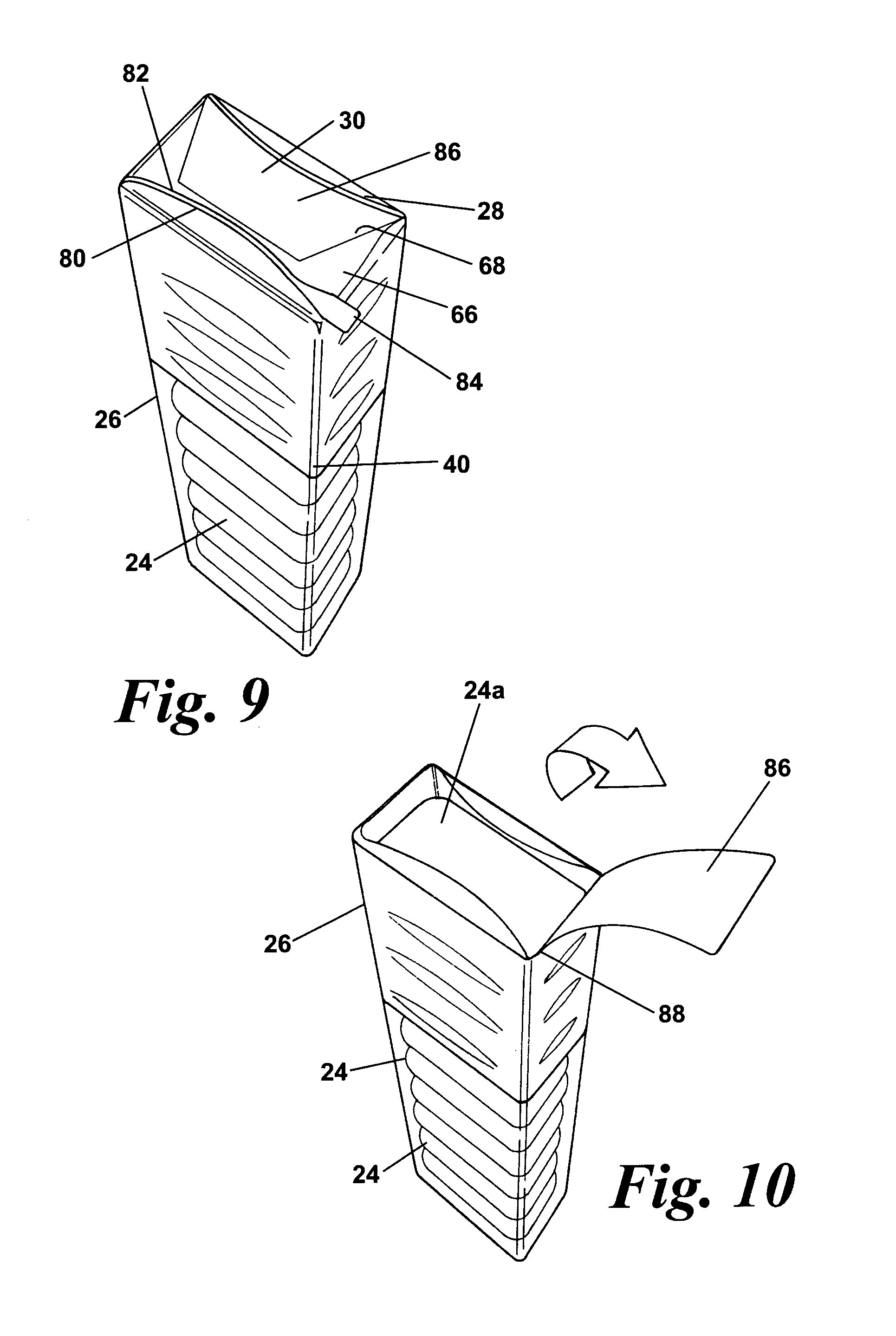
[0073] FIG. 9 is a perspective view of a stack of chewing gum pellets packaged in accordance with a third embodiment of the present invention; and
[0074] FIG. 10 is a view similar to that of FIG. 8 but illustrating the packaging of FIG. 9 after is has been opened.
[0075] The same reference numerals will be used to denote the same or equivalent features in the various embodiments described below.
[0076] FIG. 2 shows a stack 22 of chewing gum pellets 24 packaged in an outer wrapper 26, in a manner similar to that of the prior art stack 10 described above. However, unlike the prior art, the wrapper 26 in the present embodiment has a tear strip 28 which is arranged so that when the wrapper 26 is folded about the stack, it extends about the longitudinal axis and is positioned at least partially in an end cap region 30 of the wrapper adjacent an outer end face of an outermost one 24a of the pellets 24 the stack 22.
[0077] As shown in FIG. 2, the tear strip 28 is positioned at the intersection between the end cap 30 and the side wall portion 32 of the wrapper. Thus an outer longitudinal edge 34 of the tear strip is positioned within the end cap 30, whilst an inner longitudinal edge 36 is positioned just slightly into the side wall portion 32 of the wrapper substantially in line with the outer end face of the outermost pellet 24a. The tear strip 28 extends across the full width of the wrapper so that it completely encircles the end cap 30 when the wrapper is formed. This means that the end cap 30 is completely removed when the user opens the packaging using the tear strip 28. However, only a minimal amount of the side wall portion 32 of the wrapper is removed with the end cap 30. In preferred embodiments, no more than 3 mm of the side wall is removed, more preferably no more than 2 mm, and still more preferably no more than 1.5 mm.
[0078] By positioning the tear strip 28 so that it lies at least partly within the end cap 30 at one end of the stack 22, many of the disadvantages of the prior art packaging arrangements are overcome. Because the outermost end pellet 24a is effectively inboard of the tear strip 28, there is less chance of it being lost as the user opens the packaging. Furthermore, once the end pellet 24a has been removed from the stack, there will be sufficient of the side wall portion 32 of the wrapper protruding beyond the outer end face of the next pellet 24b in the stack 22 that the open end of the wrapper can be folded over by the user to encase the remaining pellets 24, so protecting them from exposure and preventing them from falling out of the packaging.
[0079] FIG. 3 is a plan view of the wrapper 26 which comprises a sheet of paper material or a sheet of metal foil. The wrapper 26 may also be made from a sheet of composite material comprising a metal foil on one side, usually the inner side 37, and a paper or other material on the outer side. The outer surface 39 of the wrapper may be printed to provide details of the product such as its name, a list of ingredients and/or a trademark etc. Regions of adhesive 38 are pre-applied to the inner and outer surfaces of the wrapper to hold it in place about the stack of pellets as will be described in more detail later.
[0080] The sheet wrapper 26 has two opposing side edges 40, 42 and two opposing longitudinal end edges 44, 46 and is generally rectangular in shape. It will be appreciated, however, that the shape of the wrapper 26 can be varied depending on the dimensions of the pellets 24 and the number of pellets in the stack 22. The tear strip 28 is located near one longitudinal end edge 44 and can be of any suitable type, including any that are presently known in the art.
[0081] In the present embodiment, the tear strip 28 is in the form of a strip of material which is affixed to the inner surface 37 of the wrapper. The tear strip 28 is fixed to the wrapper so that it extends from a first of the side edges 40 to the opposite side edge 42 substantially parallel with the first longitudinal end edge 44. A tab 48 projects from the first side edge 40 and an end of the strip of material 28 is fixed to the tab 48. When the wrapper is folded about the stack, the first side edge 40 of the wrapper overlaps the other side edge 42 and is affixed thereto by means of adhesive 38 but the tab 48 remains free so that it can be grasped by a user. The tear strip 28 is made of a material, such as a plastic, that is stronger than the rest of the wrapper so that a user is able tear open the packaging by grasping the tab 48 with the tear strip 28 attached and pulling the tear strip in a generally circumferential direction about the stack. Because the strip 28 of material is stronger than the rest of the wrapper, the wrapper tends to shear along at least one of the longitudinal side edges of the strip 28 as the user pulls the tab.
[0082] The tear strip 28 is positioned inwardly from the first longitudinal end edge 44 of the sheet wrapper 26 so that the outer longitudinal edge 34 of the strip lies within the end cap 30 formed at that end of the stack. The precise spacing of the tear strip will depend on the dimensions of the pellets and the sheet wrapper. However, in the present embodiment, the outer longitudinal edge 34 of the tear strip is spaced from the first longitudinal end edge 44 of the wrapper 28 by a distance in the range of 5 mm to 10 mm and the inner longitudinal edge 36 of the strip is spaced from the first longitudinal end edge 44 of the sheet wrapper by a distance in the range of 6 mm to 12 mm.
[0083] The wrapper 26 may be formed as part of a continuous web 50 of wrappers and applied to the stack 22 of pellets using a known wrapping machine such as the Sapal Chewpac.TM. supplied by SIG Sapal SA of Av. Du Tir Federal 44, 1024 Ecublens, Switzerland.
[0084] A method of applying the wrapper 26 to a stack 22 of chewing gum pellets 24 will now be described with reference to FIG. 4, which illustrates schematically, the sequence of folding steps taken to produce the packaging using the wrapper 26 as described above.
[0085] A stack 22 of gum pellets 24 is fed in a wrapping machine towards a vertically aligned wrapper 26 with the inner surface 37 of the wrapper facing the stack. The wrapper 26 is fed into the machine as part of a continuous web 50 and is separated from the web prior to it being folded about the stack 22. The wrapper 26 has a tear strip 28 which is aligned with the outer end face 52 of the outermost pellet 24a at one end of the stack 22.
[0086] As shown at 54, the second side edge 42 of the wrapper 26 is folded so as to lie partway across the lower surface of the stack 22 whilst the first side edge 40 is folded over the upper surface so as to project outwardly from the side of the stack. The longitudinal end edges 44, 46 of the wrapper project beyond the ends of the stack 22.
[0087] The stack of pellets 22 together with the partly folded wrapper 26 are then inverted as indicated by the arrow 56. As shown at 58, with the stack 22 inverted, the second side edge 42 of the wrapper 26 extends longitudinally about halfway across the now upper surface of the stack 22 generally parallel with a longitudinal axis 60 of the stack 22. At this point, or during the process of inverting the stack, first side portions 62 of the wrapper 26 that project beyond either end of the stack are tucked inwardly so as to contact the end faces of the stack and the wrapper is creased about fold lines 64 to partly form first and second major end closure flaps 66, 68 at either end of the stack.
[0088] The first side edge 40 of the wrapper 26 is folded over the now upper surface of the stack so as to overlie the second side edge 42 of the wrapper, as shown at 70. Second side portions 72 of the wrapper 26 that project beyond the ends of the stack 22 are then folded inwardly so as to contact the end faces of the stack and the wrapper is creased about fold lines 74 to complete the first and second major end closure flaps 66, 68 at either end. The second side portions 72 may overlap with the first side portions 62 so that the ends of the stack are completely covered.
[0089] The first major end closure flaps 66 at either end are folded down into contact with the side portions 62, 72 over the end faces of the stack 22 as shown at 75. The final stage in forming the wrapper is to fold the second major end closure flaps 68 over the first major end closure flaps 66 as shown at 76. The side portions 62, 72 and the first and second major end closure flaps 66, 68 combine to form end closures or end caps 30 of the wrapper.
[0090] In a manner well known in the art, some or all of the over lapping regions of the wrapper are adhered to one another by means of the pre-applied adhesive 38. This holds the wrapper 26 in position and can be arranged so that the packaging is sealed to protect the packaged gum pellets. Any suitable adhesive can used which may be pressure and/or heat sensitive.
[0091] FIGS. 5 to 8 illustrate an alternative embodiment of in which the tear strip 28 is positioned so that it lies wholly within an end cap 30 of the fully formed wrapper 26. The wrapper 26 in this embodiment is otherwise formed as described above in relation to the first embodiment. As illustrated in FIG. 6, with this arrangement, none of the side wall portion 32 of the wrapper 26 is removed when the package is opened. FIGS. 7 and 8 illustrate how the open end of the wrapper can be folded down after one of the pellets 24a has been removed from the opened packet to enclose and protect the remaining pellets.
[0092] FIGS. 9 and 10 illustrate a yet further embodiment of a packaging 11 for a stack of pellets. In FIGS. 9 and 10, a lower portion of the wrapper 26 is shown as being transparent so that the gum pellets 24 can be seen clearly in position. In this embodiment, the tear strip 28 is created in the wrapper by forming two spaced lines of weakness 80, 82 on the inner surface of the wrapper 26. The lines of weakness run transversely from a first side edge 40 partway across the width of the wrapper. A tab 84 projects from a first side edge 40 of the wrapper at a position between the two lines of weakness for a user to grasp. The arrangement being such that when a user pulls the tab, the wrapper preferentially tears along the two lines of weakness.
[0093] The tear strip 28 is arranged so that it is positioned wholly within an end cap 30 of the fully formed wrapper 26. Because the tear strip only extends part way across the wrapper, it only partly encircles a central region 86 of the end cap 30. As a result, the central region 86 is not completely removed from the wrapper 26 when the package is opened but remains attached along one edge 88 to form a flap. This reduces the amount of litter produced as the open end cap region 86 cannot be discarded by a user. The flap 86 can also be used to help in re-closing the package. It will be appreciated however, that the tear strip could extend across the whole width of the wrapper 28 so that the end cap 30, or at least part of it, is removed completely when the package is opened.
[0094] By forming tear strip using lines of weakness rather than a strip of material, the tear strip 28 can be shaped to provide a more attractive opening and the material within the tear strip can be printed in a different colour to add to the design effect. Thus the lines of weakness 80, 82 can follow a curvilinear path to produce a shaped opening.
[0095] The lines of weakness 80, 82 can be produced using any suitable method but are preferably produced by laser etching the inner surface of the wrapper. Other methods for producing the lines of weakness include etching by means other than a laser, scoring the inner surface or by forming perforations which extend through at least an inner layer of the wrapper. Preferably, the formation of the lines of weakness should not destroy the integrity of the formed wrapper, particularly where the stack is single wrapped. Thus, for example, if a line of weakness is produced using perforations, these should preferably only extend though one or more inner layers and should not extend completely through the wrapper. In an alternative embodiment (not shown), rather than producing two spaced lines of weakness to form a tear strip 28, a tear guide can be formed by producing only a single line of weakness in the wrapper. The line of weakness extends at least partway across the width of the wrapper so that in the fully formed wrapper it encircles the whole or part of an end cap region of the wrapper 26. A tab can be formed on the first side edge of the wrapper between the line of weakness and the first longitudinal end edge 44. When the wrapper is fully formed, the tab can be grasped by a user and pulled to initiate tearing of the wrapper along the line of weakness to open the package. The line of weakness can be formed so as to extend across the full width of the wrapper so that it completely encircles the whole or part of the end cap which is completely separated from the rest of the wrapper when the package is opened. Alternatively, the line of weakness may only extend part way across the wrapper 26 so that it only partly encircles the whole or part of an end cap. In this case, the part of the end cap 30 that lies within the line of weakness will remain attached to the rest of the packaging to form a flap when the packaging is opened. The line of weakness may follow a curvilinear path to provide a shaped opening.
[0096] Whilst it is particularly advantageous that the tear guide is located at least partly in an end cap region of the wrapper, an advantageous packaging for confectionary pellets can be provided by forming a tear guide by means of one or more lines of weakness in the wrapper, even where the guide is located in the side wall region of the completed wrapper. A previously noted, use of a laser-etched or otherwise formed line of weakness enables a tear guide to be formed in the wrapper which is substantially invisible to a user, and which therefore does not affect the aesthetic features of the wrapper.
[0097] It will be appreciated that the precise nature of the wrapper and the method of applying the wrapper to the stack of pellets can be varied without departing from the scope of the invention. For example, a second inner wrapper (not shown) could be provided and which will be positioned about the stack of pellets before the wrapper 26, which becomes an outer wrapper, is applied. Furthermore, each pellet in the stack may be individually wrapped. It should also be appreciated that the packaging and method in accordance with the invention is not limited for use in packaging gum pellets but can be adapted for use in packaging other confectionery products or items which can be formed into a stack. For example, hard boiled sweets, candies, chocolates, toffee or mints and other similar confectionery products can be packaged in accordance with the invention.
[0098] Whereas the invention has been described in relation to what is presently considered to be the most practical and preferred embodiment, it is to be understood that the invention is not limited to the disclosed arrangements but rather is intended to cover various modifications and equivalent constructions included within the spirit and scope of the invention.
* * * * *
D00000
D00001
D00002
D00003
D00004
D00005
XML
uspto.report is an independent third-party trademark research tool that is not affiliated, endorsed, or sponsored by the United States Patent and Trademark Office (USPTO) or any other governmental organization. The information provided by uspto.report is based on publicly available data at the time of writing and is intended for informational purposes only.
While we strive to provide accurate and up-to-date information, we do not guarantee the accuracy, completeness, reliability, or suitability of the information displayed on this site. The use of this site is at your own risk. Any reliance you place on such information is therefore strictly at your own risk.
All official trademark data, including owner information, should be verified by visiting the official USPTO website at www.uspto.gov. This site is not intended to replace professional legal advice and should not be used as a substitute for consulting with a legal professional who is knowledgeable about trademark law.