Decorative Article Support
McNamara; Paul
U.S. patent application number 12/493874 was filed with the patent office on 2010-12-30 for decorative article support. Invention is credited to Paul McNamara.
| Application Number | 20100326996 12/493874 |
| Document ID | / |
| Family ID | 43379600 |
| Filed Date | 2010-12-30 |
| United States Patent Application | 20100326996 |
| Kind Code | A1 |
| McNamara; Paul | December 30, 2010 |
Decorative Article Support
Abstract
A decorative article support device which can be attached to a container or container lid. The device includes a chassis, a mount with a receptacle for displaying a decorative or other article and flexible legs attached to the chassis. The flexible legs enable the support device to be detachably attached to the container or container lid. In one embodiment, the flexible legs have an extensible part which enables the support device to be attached to containers of varying sizes. Decorative or other articles, such as small balloons, may be engaged with the receptacle on the chassis.
| Inventors: | McNamara; Paul; (Northamppton, MA) |
| Correspondence Address: |
    CLIFFORD H. KRAFT
    320 ROBIN HILL DR.
    NAPERVILLE
    IL
    60540
    US
|
| Family ID: | 43379600 |
| Appl. No.: | 12/493874 |
| Filed: | June 29, 2009 |
| Current U.S. Class: | 220/694 |
| Current CPC Class: | B65D 51/245 20130101; B65D 25/20 20130101; B65D 2203/00 20130101 |
| Class at Publication: | 220/694 |
| International Class: | B65D 25/00 20060101 B65D025/00 |
Claims
1. A device which can be attached to a container or container lid, said device comprising: a) a chassis which can support a decorative or other article; and b) flexible legs attached to the chassis which enable the device to be detachably attached to the container or container lid.
2. The device of claim 1 wherein the chassis has at least one mount to which a decorative or other article can be attached.
3. The device of claim 2 wherein the at least one mount has a receptacle in which a decorative or other article can be placed or attached.
4. The device of claim 1 wherein the flexible legs are designed with an inward bend to facilitate a secure grip on an indented narrower portion of the container or container lid.
5. The device of claim 1 wherein the distal ends of the flexible legs are shaped such that they securely grip an indented narrower portion of the container or container lid, wherein the shape of said distal ends may include a spherical, semi-spherical, oval or other shape.
6. The device of claim 1 wherein the flexible legs have an extensible part which enables the device to be attached to containers or container lids of varying diameters.
7. The device of claim 6 wherein the extensible part of the flexible leg uses a sliding, swing-out, or attachment-based mechanism.
8. The device of claim 1 wherein the flexible legs are made of metal, wood, plastic or any other flexible material.
9. A device which can be attached to a container or container lid, said device comprising: a) a chassis having at least one mount for supporting a decorative or other article; and b) flexible legs attached to the chassis which enable the device to be detachably attached to the container or container lid, said flexible legs being designed with an inward bend.
10. A device which can be attached to a container or container lid, said device comprising: a) a chassis; b) on the chassis, at least one mount having a receptacle in which a decorative or other article can be placed or attached; and c) flexible legs attached to the chassis which enable the device to be detachably attached to the container or container lid, said flexible legs being designed with an inward bend and distal ends of said flexible legs being shaped such that they securely grip an indented narrower portion of the container or container lid, wherein the shape of said distal ends may include a spherical, semi-spherical, oval or other shape.
11. A device which can be attached to a container or container lid, said device comprising: a) a chassis; b) on the chassis, at least one mount having a receptacle in which a decorative or other article can be placed or attached; and c) flexible legs attached to the chassis which enable the device to be detachably attached to the container or container lid, wherein: i) the flexible legs are designed with an inward bend, ii) distal ends of the flexible legs are shaped such that they securely grip an indented narrower portion of the container or container lid, wherein the shape of said distal ends may include a spherical, semi-spherical, oval or other shape, and iii) the flexible legs have an extensible part.
Description
BACKGROUND OF THE INVENTION
[0001] 1. Field of the Invention
[0002] The present invention relates to a detachable device for enabling display of decorative items on jars, bottles and other containers. Specifically, the device has flexible legs which snap on to the containers or their lids and a receptacle to which decorative items can be attached.
[0003] 2. Description of Related Art
[0004] Candles in glass containers are common and come in a variety of sizes. A variety of decorative lids have been developed, especially for containerized or apothecary jars. Decorative lids have been developed that replace the standard lid that accompanies the apothecary jar style container. Decorative lids come in a variety of styles to fit seasons or holidays. Apart from apothecary jars, decorative lids can be used with other jars, bottles and containers. Personalizing the decorative lids is difficult since the process may involve casting resin, permanently attaching a decoration or other inconvenient procedures. Consequently, a device that can be attached to a container or container lid with a snap-fit and support an inexpensive decorative item would be advantageous.
[0005] There has been substantial research and experimentation in various mechanical designs for the integration of decorative articles with the lid of a container.
[0006] U.S. Publication No. 2005/0277076 relates to a venting chassis and includes a radial turbine and a ceramic base and elevated ornamentation platform. The ornamentation platform has a flat top, upon which the ornamentation is mounted and a plurality of legs, which support the platform above the base. However, it has multiple components with intricate design.
[0007] Japanese Application No. JP2002158976 relates to a display rack for bottle caps that fit on tops of pet bottles, which can be conformed to every series of bottle caps, and a base seat piece and connector therefor, which are economically mass-producible. However, this is designed for tops of pet bottles.
[0008] U.S. Pat. No. 6,766,902 relates to a container assembly for three dimensional premium item mounted removably to a beverage cup for handling as a single unit which has a clear, plastic cover member, and first and second base members. However, it has multiple components designed for beverage cup lids and does not have legs for attaching to any container or lid.
[0009] U.S. Pat. No. 6,663,384 discloses a venting plate for an apothecary jar candle which includes a ceramic venting chassis and a decorative three dimensional ornamentation bonded to the chassis. However, the decorative ornamentation is not detachable.
[0010] U.S. Pat. No. 6,231,336 relates to a shade structure for a candle, and in particular, the shade structure comprising a container body for containing a candle, a shade body with a center air hole and detachably mounted onto the circumferential edge of the container body, and a covering plate having a center hole aligned with the center air hole of the shade body. However, it is not designed to flexibly attach different decorative articles.
SUMMARY OF THE INVENTION
[0011] Accordingly, one object of the present invention is to provide a simple, flexible and inexpensive device which enables display of decorative or other articles on jars, bottles and other containers.
[0012] Another object of the present invention is to provide a device for displaying decorative or other items which can be conveniently attached to and detached from any container or container lid.
[0013] One more object of the present invention is to provide a device for displaying decorative or other items which has flexible legs which securely grip a container or container lid.
[0014] Yet another object of the present invention is to provide a device for displaying decorative or other items which can be attached to containers or container lids of varying sizes.
[0015] The decorative article support device, as per this invention, can be attached to a container or container lid and includes:
[0016] a) a chassis which can support a decorative or other article,
[0017] b) flexible legs attached to the chassis which enable the device to be detachably attached to the container or container lid,
[0018] c) at least one mount, on the chassis, to which a decorative or other article can be attached,
[0019] d) a receptacle in the at least one mount in which a decorative or other article can be placed or attached,
[0020] e) the flexible legs (as in (b) above) designed with an inward bend to facilitate a secure grip on an indented narrower portion of the container or container lid,
[0021] f) the flexible legs (as in (b) above) having distal ends shaped such that they securely grip an indented narrower portion of the container or container lid, wherein the shape of said distal ends may include a spherical, semi-spherical, oval or other shape,
[0022] g) the flexible legs (as in (b) above) having an extensible part which enables the device to be attached to containers or container lids of varying diameters, wherein the extensible part uses a sliding, swing-out, or attachment-based mechanism, and
[0023] h) the flexible legs (as in (b) above) are made of metal, wood, plastic or any other flexible material.
[0024] One of the advantages of the present invention is that the flexible legs allow the user to add a decorative element directly to the lid. The original container and lid are intact and the decorative element is secured to the complete intact unit and does not require removing the lid. This is in contrast to some of the known related art which involve adding the decorative element to the top of a jar. However, in order to effect such decoration the cover that comes with the jar has to be removed.
BRIEF DESCRIPTION OF THE DRAWINGS
[0025] Understanding of the present invention and the various aspects thereof will be facilitated by reference to the accompanying drawing figures, provided for purposes of illustration only and not intended to define the scope of the invention, of which:
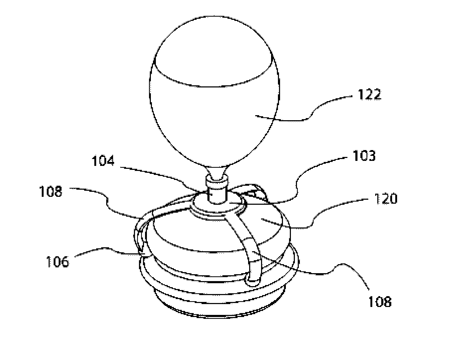
[0026] FIG. 1 is a three quarter perspective, view of the present invention as engaged with a standard apothecary jar candle lid and engaged with a decorative element;
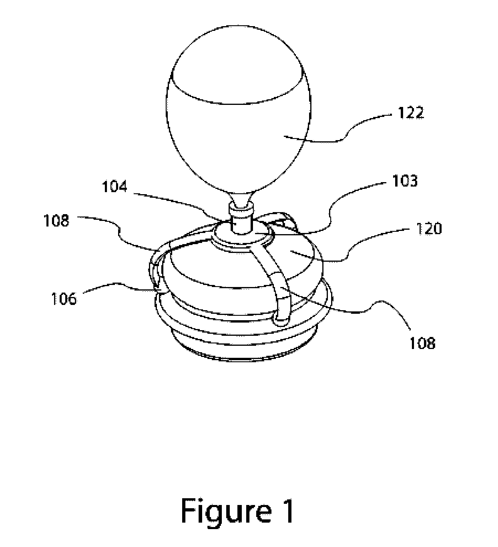
[0027] FIG. 2 is a three-quarter perspective, exploded view of a preferred embodiment of the present invention;
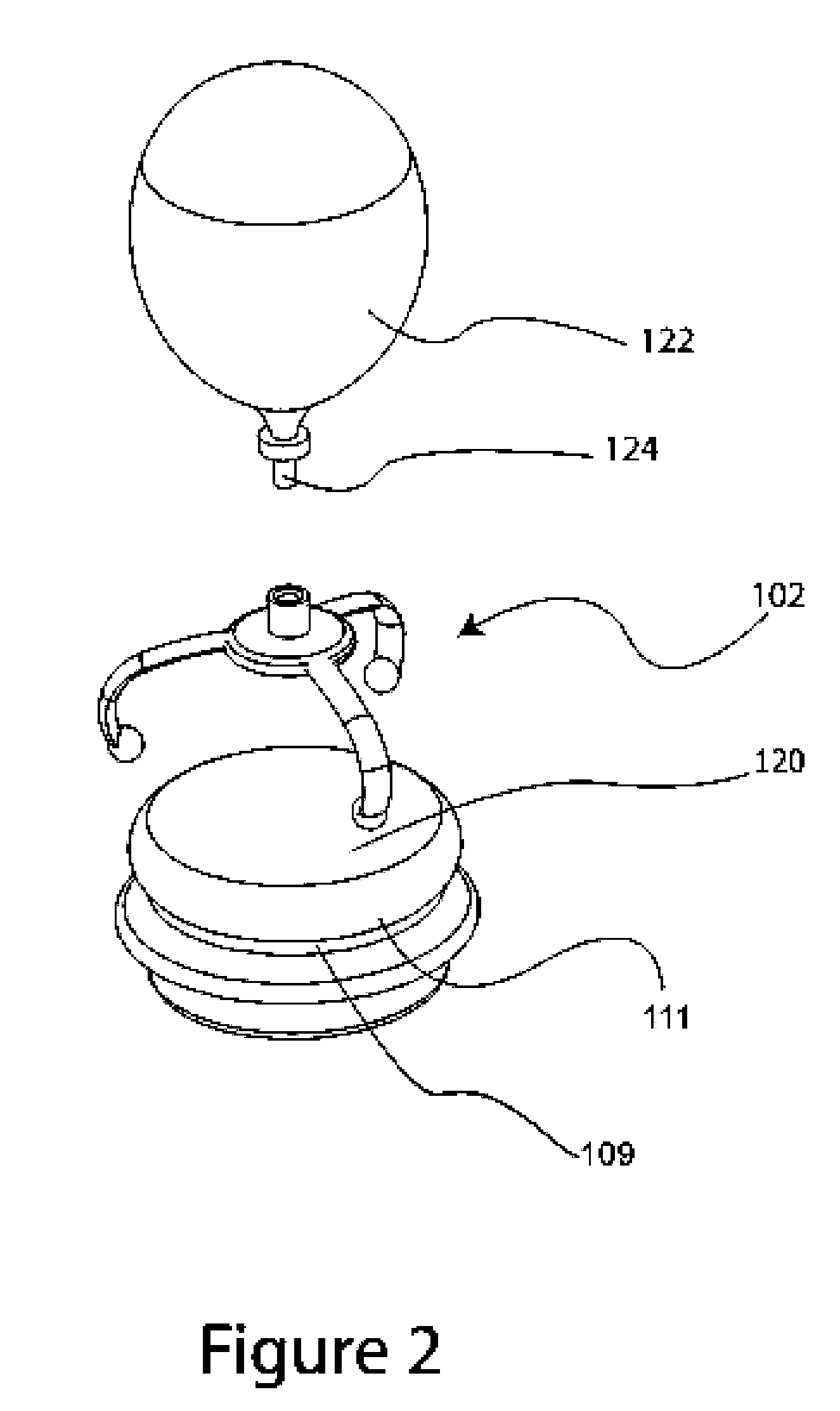
[0028] FIG. 3 is a three-quarter perspective, view of a preferred embodiment of the present invention;
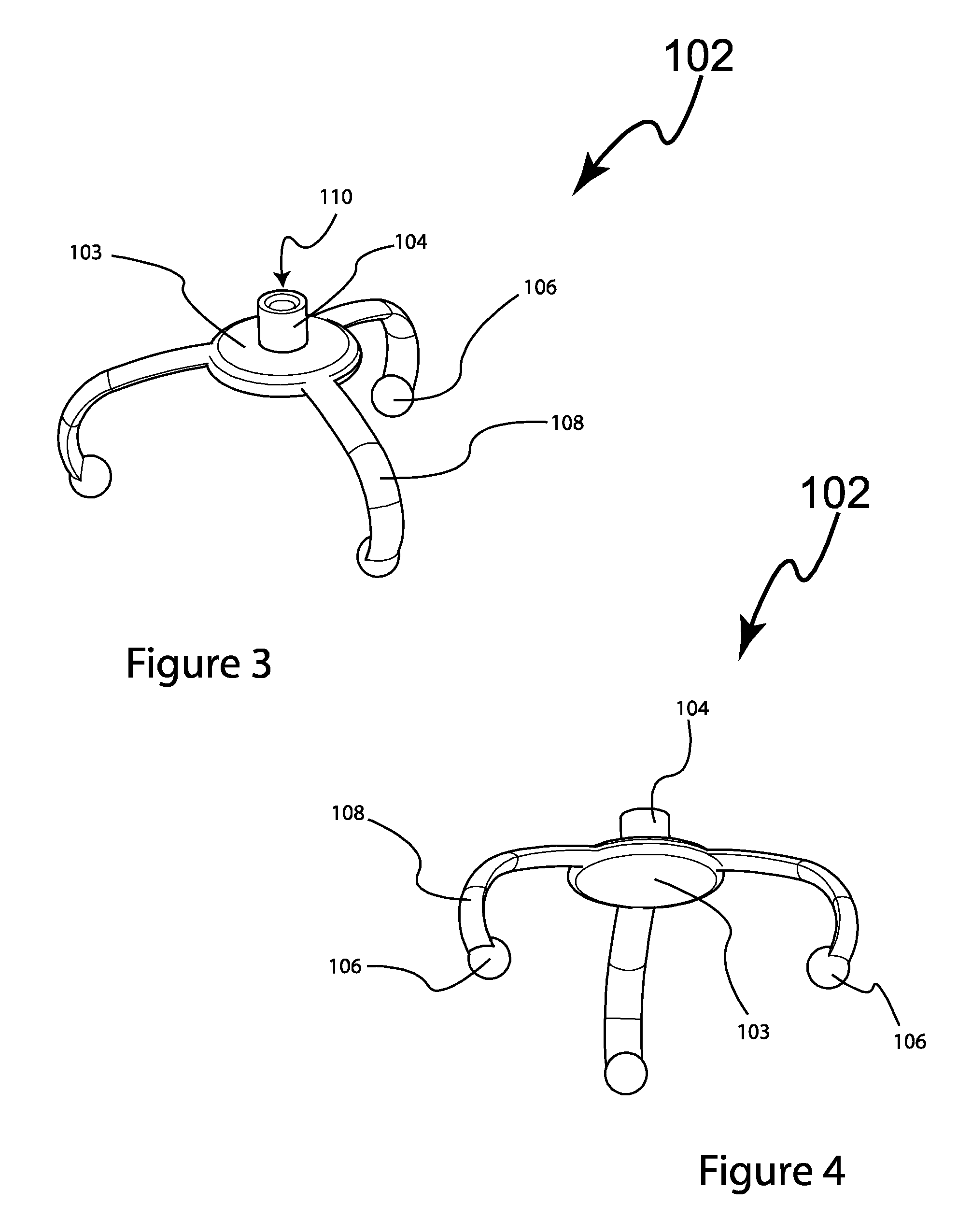
[0029] FIG. 4 is a three-quarter perspective, bottom view of a preferred embodiment of the present invention;
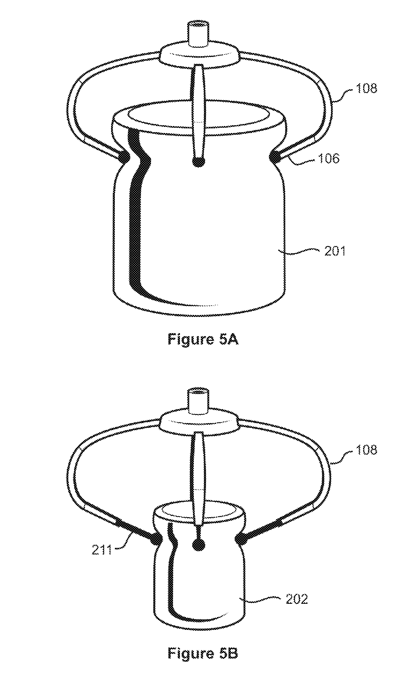
[0030] FIGS. 5A & 5B illustrate how the same support device of the present invention can be attached to a wide jar or a narrow jar by extending/retracting an extensible part of the flexible legs;
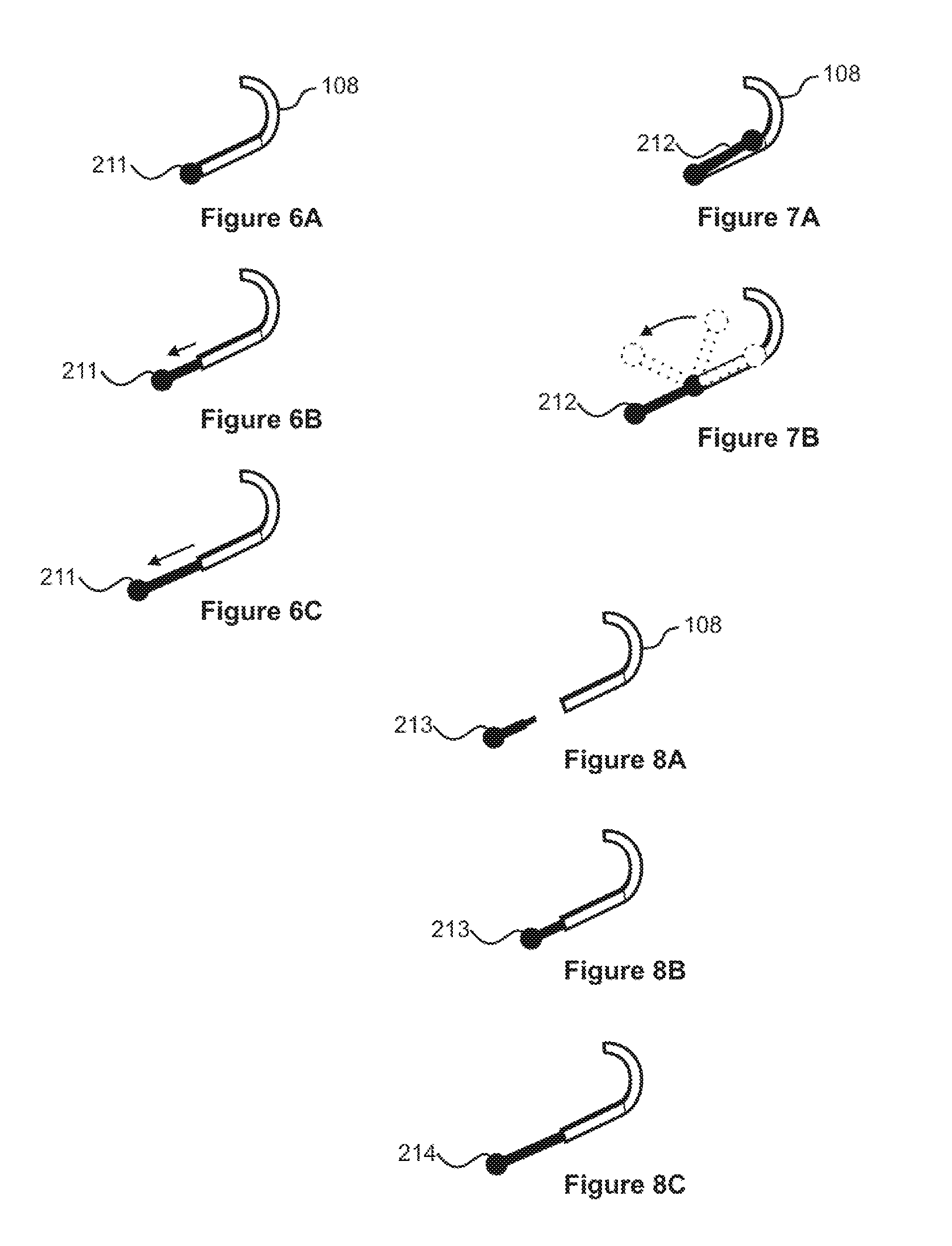
[0031] FIGS. 6A to 6C illustrate a sliding/telescopic mechanism for extending/retracting the extensible part of the flexible legs;
[0032] FIGS. 7A & 7B illustrate a swing-out mechanism for extending/retracting the extensible part of the flexible legs; and
[0033] FIGS. 8A to 8C illustrate an attachment mechanism for extending/retracting the flexible legs.
DETAILED DESCRIPTION OF THE EMBODIMENTS OF THE INVENTION
[0034] In this specification, a chassis means a supporting frame of a structure to which other components are attached. A mount means a support or stand on which something can be fixed or attached. The term container covers bottles, jars and other containers.
[0035] Embodiments of the support device (i.e., decorative article support device) of the present invention are illustrated in FIGS. 1 to 8C.
[0036] One embodiment of the present invention 102 (FIGS. 3 & 4) comprises a chassis 103 that is engaged with flexible legs 108 with formed (i.e., with spherical, semi-spherical, oval & other shapes) distal ends 106. The chassis 103 has a mount 104 which has a receptacle 110. The embodiment 102 is removably engaged with a decorative element/article 122 (FIGS. 1 & 2) and fits over the apothecary jar lid 120. Many lids 120 have a narrower portion 109 and a wider portion 111. The chassis 103 is designed to engage with an apothecary jar lid 120, due to use of flexible legs which bend and open up to slip over the wider portion of the lid and snap into place in the narrow portion of the lid. The flexible legs 108 are designed with an inward bend (see FIG. 1) so that the legs are not obstructed by (and wrap around) the wider portion 111 of the container or container lid. This facilitates a secure grip on the indented narrower portion 109 of the container or container lid. In this embodiment three legs are attached to the chassis. However, any number of multiple legs can be attached to the chassis. Also, the chassis 103 can be circular, oval, rectangular or any other shape.
[0037] Even though the mount 104 and receptacle 110 are cylindrical in shape in this embodiment, they can very well be square, curved or any other shape. Also, the chassis can have more than one mount and/or receptacle.
[0038] In a preferred embodiment of the support device 102 of the invention, the distal ends 106 of the legs 108 are shaped so as to conform to the indentation created by the narrower portion 109 of the jar lid 120. A plurality of legs 108 extend from a chassis 103. The legs 108 are of a flexible material such as wood, metal or plastics which provide a combination of advantages such as a balance of flexibility & rigidity, low cost and durability. The flexible legs 108 are configured to flex in such a manner as to bend over the wider portion 111 and snap into the narrower portion 109, of the jar lid 120, providing a means of securely engaging the chassis 103 with the apothecary jar lid 120. The flexible legs also make it easy to disengage from the lid. When the distal ends 106 are engaged with the lid 120, the chassis is fixed in place at the top of the lid 120. The chassis 103 provides a horizontal surface and receptacle 110 that can support a decorative article 122. In one embodiment, the decorative article 122 comprises a volume with a distal portion 124 that engages with the receptacle 110. In combination, the decorative article 122 and the embodiment 102 provide a means of decorating an apothecary jar lid 120 such as those used with containerized candles.
[0039] In a preferred embodiment of the present invention, the flexible legs 108 are extensible. The extensible legs enable the support device 102 to be fitted on to containers having varying sizes by extending (for narrow containers 202) and retracting (for wide containers 201) the extensible part of the legs as per the size of the container/lid. The legs of the device can be made extensible by using a sliding, swing-out, attachment-based or any other mechanism.
[0040] FIGS. 5A & 5B illustrate how the extensible leg 211 attached to the flexible legs 108 enable the support device 102 to be attached to a wide container 201 or a narrow container 202 by retracting or extending the extensible part 211 which is attached to the distal end 106 of the flexible legs 108. The inward bend design of the flexible legs 108 causes the extensible legs 211 to move inwards when extended, thereby enabling a secure grip on narrow containers 202 with smaller diameters also.
[0041] FIGS. 6A to 6C illustrate a flexible leg 108 having a sliding extensible leg 211 mechanism. The extensible legs 211 can be extended as per the diameter of the container or lid (and locked in position) to ensure a secure attachment. FIGS. 7A & 7B illustrate a flexible leg 108 having a swing-out extensible leg 212 mechanism. The extensible legs 212 can be swung out to fit a narrow container or swung in to fit a wide container. FIGS. 8A to 8C illustrate a flexible leg 108 having a detachable attachment-based extensible leg 213 mechanism. Extensible legs 213, 214 of the appropriate length can be attached to the flexible leg 108 depending on the diameter of the container or lid. Other extension mechanisms can also be used for the extensible legs.
[0042] It can be seen, from the features described herein, that the present invention has been designed to serve multiple objectives. On the one hand, the flexible, inward bent and extensible legs enable the present invention to be detachably attached in a secure manner to containers or lids of varying sizes. At the same time the design of the invention and use of versatile and low cost materials such as wood, metal, plastics or any other material with these qualities ensures that the support device also has the required rigidity and capability to support decorative or other articles. In other words the present invention achieves a balance between flexibility, rigidity, adaptability and low cost.
[0043] Even though in the embodiments of the present invention described hereinbefore, reference is made to an apothecary jar and lid, the same concepts, methods and features are applicable to any container or container lid having a narrower indented portion below a wider portion. Thus, this description fully describes use of this invention device with any container or container lid.
[0044] It will thus be seen that the objects set forth above, among those elucidated in, or made apparent from, the preceding description, are efficiently attained and, since certain changes may be made in the above construction without departing from the scope of the invention, it is intended that all matter contained in the above description or shown on the accompanying drawing figures shall be interpreted as illustrative only and not in a limiting sense.
[0045] It is also to be understood that the following claims are intended to cover all of the generic and specific features of the invention herein described and all statements of the scope of the invention which, as a matter of language, might be said to fall there between.
* * * * *
D00000
D00001
D00002
D00003
D00004
D00005
XML
uspto.report is an independent third-party trademark research tool that is not affiliated, endorsed, or sponsored by the United States Patent and Trademark Office (USPTO) or any other governmental organization. The information provided by uspto.report is based on publicly available data at the time of writing and is intended for informational purposes only.
While we strive to provide accurate and up-to-date information, we do not guarantee the accuracy, completeness, reliability, or suitability of the information displayed on this site. The use of this site is at your own risk. Any reliance you place on such information is therefore strictly at your own risk.
All official trademark data, including owner information, should be verified by visiting the official USPTO website at www.uspto.gov. This site is not intended to replace professional legal advice and should not be used as a substitute for consulting with a legal professional who is knowledgeable about trademark law.