Infiltration/inflow Control For Membrane Bioreactor
Barnes; Dennis J.
U.S. patent application number 12/594323 was filed with the patent office on 2010-12-30 for infiltration/inflow control for membrane bioreactor. Invention is credited to Dennis J. Barnes.
| Application Number | 20100326906 12/594323 |
| Document ID | / |
| Family ID | 39672937 |
| Filed Date | 2010-12-30 |


| United States Patent Application | 20100326906 |
| Kind Code | A1 |
| Barnes; Dennis J. | December 30, 2010 |
INFILTRATION/INFLOW CONTROL FOR MEMBRANE BIOREACTOR
Abstract
A method and system for wastewater treatment comprising a first treatment zone (11) fluidly connected to one or more further treatment zones (12, 13, 14), a membrane module (16) comprising a filter membrane positioned in or fluidly connected to the further treatment zone (14), a gravity settling device (15) fluidly connected to the first treatment zone (11) to receive overflow therefrom; and a flow control device (23) between the first treatment zone (11) and the gravity settling device (15) to control the flow of liquid therebetween.
| Inventors: | Barnes; Dennis J.; (Oconomowoc, WI) |
| Correspondence Address: |
    SIEMENS CORPORATION;INTELLECTUAL PROPERTY DEPARTMENT
    170 WOOD AVENUE SOUTH
    ISELIN
    NJ
    08830
    US
|
| Family ID: | 39672937 |
| Appl. No.: | 12/594323 |
| Filed: | April 1, 2008 |
| PCT Filed: | April 1, 2008 |
| PCT NO: | PCT/US08/04224 |
| 371 Date: | March 17, 2010 |
Related U.S. Patent Documents
| Application Number | Filing Date | Patent Number | ||
|---|---|---|---|---|
| 60909552 | Apr 2, 2007 | |||
| Current U.S. Class: | 210/614 ; 210/137 |
| Current CPC Class: | C02F 2103/001 20130101; C02F 3/1268 20130101; C02F 2209/40 20130101; Y02W 10/15 20150501; C02F 1/008 20130101; C02F 9/00 20130101; C02F 1/52 20130101; C02F 3/006 20130101; C02F 2301/043 20130101; C02F 2209/42 20130101; Y02W 10/10 20150501; C02F 2209/10 20130101; C02F 1/44 20130101 |
| Class at Publication: | 210/614 ; 210/137 |
| International Class: | C02F 9/14 20060101 C02F009/14; C02F 3/00 20060101 C02F003/00; C02F 1/44 20060101 C02F001/44 |
Claims
1. A method of treating wastewater comprising: flowing a wastewater through one or more treatment zones to produce a fluid product which is passed through a filter membrane to produce a concentrated mixed liquor and a filtrate; returning at least a portion of the concentrated mixed liquor to at least one of said treatment zones; when the flow of wastewater exceeds a predetermined level, flowing a portion of said returned mixed liquor to a gravity settling device; clarifying the mixed liquor within the gravity settling device; and controlling the size of the portion of returned mixed liquor in dependence on the flow of wastewater.
2. A method according to claim 1 further comprising controlling the flow of liquid between treatment zones and the filter membrane by one or more pumps operating in response to the liquid level in the first treatment zone or a furthest upstream treatment zone.
3. A method according to claim 1 further comprising controlling the flow of liquid between treatment zones and the filter membrane is by a weir in the first or the furthest upstream treatment zone, such that where the influent flow rate is higher than a predetermined level, the liquid level in the first treatment zone or the furthest upstream treatment zone rises and liquid flows over the weir to the gravity-settling device.
4. A method according to claim 3 wherein the weir is a fixed weir.
5. A method according to claim 3 wherein the height of the weir is adjustable.
6. A method according to claim 5 wherein the weir height is automatically adjustable based on an influent flow meter signal or other process measurement.
7. A method according to claim 1 further comprising controlling the ratio between the amount of mixed liquor from the membrane filter which is returned to the upstream treatment zones and the amount of returned mixed liquor which is fed to the downstream treatment zones and to a feed side of the membrane filter.
8. A method according to claim 7 further comprising controlling the liquid flow ratio between the upstream and downstream treatment zones by calculating the proportion of the total flow being treated by the gravity-settling device based on measurements of the total influent flow rate to the system and the feed flow being treated by the membrane filter.
9. A method according to claim 8 wherein the proportion of returned mixed liquor to be sent via the upstream treatment zones to the gravity-settling device is calculated by a programmable control device using a mass balance equation to determine the flow ratio required to maintain the required Mixed Liquor Suspended Solids (MLSS) concentration in the liquid flow being transferred to the gravity-settling device.
10. A method according to claim 9 wherein the mass balance equation is a function includes one or more of the following variables: 1) the average Total Suspended Solids (TSS) concentration in the mixed liquor. 2) the desired MLSS concentration in the upstream treatment zones. 3) the total influent flow to the treatment process, and 4) the percentage of that flow being treated by the gravity settling device.
11. A method according to claim 1 further comprising returning sludge separated from the mixed liquor in the gravity settling device to a treatment zone downstream of the treatment zone feeding the gravity settling device.
12. A wastewater treatment system comprising: a first treatment zone fluidly connected to one or more further treatment zones; a membrane module comprising a filter membrane positioned in or fluidly connected to the further treatment zone; a gravity settling device fluidly connected to the first treatment zone to receive overflow therefrom; and a flow control device between the first treatment zone and the gravity settling device to control the flow of liquid therebetween.
13. A wastewater treatment system according to claim 12 further comprising one or more pumps operable in response to the liquid level in the first treatment zone or a furthest upstream treatment zone to control the flow of liquid between treatment zones and the filter membrane.
14. A wastewater treatment system according to claim 12 further comprising a weir in the first or the furthest upstream treatment zone, wherein the flow of liquid between treatment zones and the filter membrane is controlled by a weir such that where the influent flow rate is higher than a predetermined level, the liquid level in the first treatment zone or the furthest upstream treatment zone rises and liquid flows over the weir to the gravity-settling device.
15. A wastewater treatment system according to claim 14 wherein the weir is a fixed weir.
16. A wastewater treatment system according to claim 14 wherein the height of the weir is adjustable.
17. A wastewater treatment system according to claim 16 wherein the weir height is automatically adjustable based on an influent flow meter signal or other process measurement.
18. A wastewater treatment system according to claim comprising control means for controlling the ratio between the amount of mixed liquor from the membrane filter which is returned to the upstream treatment zones and the amount of returned mixed liquor which is fed to the downstream treatment zones and to a feed side of the membrane filter.
19. A wastewater treatment system according to claim 18 wherein the control means controls the liquid flow ratio between the upstream and downstream treatment zones by calculating the proportion of the total flow being treated by the gravity-settling device based on measurements of the total influent flow rate to the system and the feed flow being treated by the membrane filter.
20. A wastewater treatment system according to claim 19 wherein the proportion of returned mixed liquor to be sent via the upstream treatment zones to the gravity-settling device is calculated by a programmable control device using a mass balance equation to determine the flow ratio required to maintain the required Mixed Liquor Suspended Solids (MLSS) concentration in the liquid flow being transferred to the gravity-settling device.
21. A wastewater treatment system according to claim 20 wherein the mass balance equation is a function includes one or more of the following variables: -- 3) the average Total Suspended Solids (TSS) concentration in the mixed liquor. 4) the desired MLSS concentration in the upstream treatment zones. 3) the total influent flow to the treatment process, and 4) the percentage of that flow being treated by the gravity settling device.
22. A wastewater treatment system according to claim 12 further comprising means for returning sludge separated from the mixed liquor in the gravity settling device to a treatment zone downstream of the treatment zone feeding the gravity settling device.
Description
BACKGROUND OF INVENTION
[0001] 1. Field of Invention
[0002] The present invention relates to a system and method for treating wastewater, and more particularly to a wastewater treatment system and method utilizing a membrane bioreactor.
[0003] 2. Discussion of Related Art
[0004] The importance of membrane for treatment of waste water is growing rapidly. With the arrival of submerged membrane processes where membrane modules are immersed in a large feed tank and filtrate is collected typically through suction applied to the filtrate side of the membrane, membrane bioreactors (MBRs) combining biological and physical processes in one stage promise to be more compact, efficient and economic. Membrane bioreactors are typically sized to accommodate community and large-scale sewage treatment. A need has been found for these systems to periodically handle large flows of influent caused by peak rain events during storms and the like. Further a need has found to provide a system which automatically compensates for such large flows of influent.
SUMMARY OF INVENTION
[0005] In accordance with one or more embodiments, the invention relates to a system and method of treating wastewater.
[0006] In one embodiment, a wastewater treatment system includes a first treatment zone fluidly connected to one or more further treatment zones. A membrane module comprising a filter membrane is positioned in or fluidly connected to the further treatment zone. A gravity settling device is fluidly connected to the first treatment zone to receive overflow therefrom. A flow control device is positioned between the first treatment zone and the gravity settling device to control the flow of liquid therebetween.
[0007] Another embodiment is directed to a method of treating wastewater which includes flowing a wastewater through one or more treatment zones to produce a fluid product which is passed through a filter membrane to produce a concentrated mixed liquor and a filtrate, returning at least a portion of the concentrated mixed liquor to at least one of said treatment zones, when the flow of wastewater exceeds a predetermined level, flowing a portion of said returned mixed liquor to a gravity settling device, clarifying the mixed liquor within the gravity settling device and controlling the size of the portion of returned mixed liquor in dependence on the flow of wastewater.
[0008] The control of flow of excess influent to the gravity settling device may be performed using a variety of arrangements. The flow of liquid between treatment zones and the filter membrane would typically be controlled by pumps operating in response to the liquid level in the first treatment zone or furthest upstream treatment zone. In one embodiment, the flow of liquid is regulated by a weir in the first or furthest upstream treatment zone. If the influent flow rate is higher than what the filter membrane can handle, the liquid level in the first treatment zone will rise and liquid will start to flow over the weir and flow to the gravity-settling device or devices.
[0009] The weir may be a fixed weir but other embodiments may include a weir whose height is manually adjustable, or automatically adjustable based on an influent flow meter signal or other process measurement. Other embodiments of the invention may also use valves, gates, or other like devices to regulate the flow split between the gravity settling device(s) and the membrane filter.
[0010] Another embodiment of the invention provides flow of feed liquid by gravity to the membrane filter and a pump for return of excess liquid back to the biological process zones. In this embodiment an adjustable weir, gate, valve or other like device is provided to restrict the flow to the membrane filter resulting in the liquid levels in the upstream treatment zones increasing to a level where the excess inflow is diverted to the gravity settling device.
[0011] Another embodiment of the invention controls the split between the amount of mixed liquor from the membrane filter which is returned to the upstream treatment zones and thus to the gravity-settling device and the amount of returned mixed liquor which is fed to the downstream treatment zones and eventually to feed side of the membrane filter.
[0012] One preferred method of controlling the liquid flow split between the upstream and downstream treatment zones is to measure the influent flow rate to the system and the feed flow being treated by the membrane filter to calculate the proportion of the total flow being treated by the gravity-settling device(s). The desired percentage of returned mixed liquor to be sent via the upstream treatment zones to the gravity-settling device(s) can then be calculated by a Programmed Logic Controller (PLC) or like device using a mass balance equation to determine the flow split required to maintain the required Mixed Liquor Suspended Solids (MLSS) concentration in the liquid flow being transferred to the gravity-settling device(s).
[0013] The mass balance equation may be a function of at least four variables: --
[0014] 1) the average Total Suspended Solids (TSS) concentration in the mixed liquor. This can be provided by user input or measured with TSS probes.
[0015] 2) the desired MLSS concentration in the upstream treatment zones (which may be verified with a TSS probe).
[0016] 3) the influent flow to the treatment process, and
[0017] 4) the percentage of that flow being treated by the gravity settling device(s).
[0018] Preferably, the process may use multiple treatment zones in series, with the ability to maintain different food to micro-organism ratios and different dissolved oxygen concentrations in each treatment zone. For preference, the sludge separated from the mixed liquor in the gravity settling device is returned to a treatment zone downstream of the treatment zone feeding the gravity settling device.
BRIEF DESCRIPTION OF DRAWINGS
[0019] A preferred embodiment of the invention will now be described, by way of example only, with reference to the accompanying drawing in which:
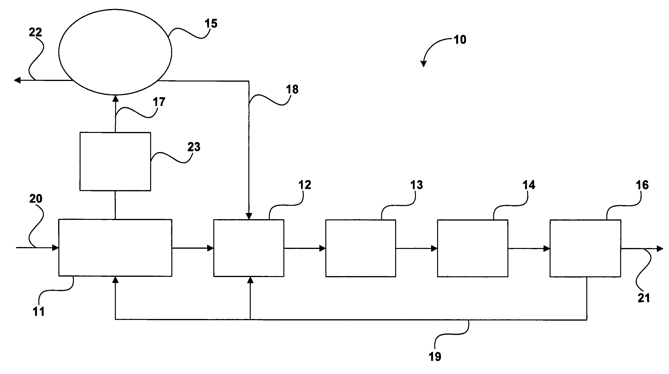
[0020] FIG. 1 shows a schematic representation of a system in accordance with one embodiment of the invention, and
[0021] FIG. 2 shows a schematic representation of a system in accordance with another embodiment of the invention.
DETAILED DESCRIPTION
[0022] This invention is not limited in its application to the details of construction and the arrangement of components set forth in the following description or illustrated in the drawing. The invention is capable of other embodiments and of being practiced or of being carried out in various ways. Also, the phraseology and terminology used herein is for the purpose of description and should not be regarded as limiting. The use of "including," "comprising," or "having," "containing," "involving," and variations thereof herein, is meant to encompass the items listed thereafter and equivalents thereof as well as additional items.
[0023] This invention may be directed to wastewater treatment systems utilizing membrane bioreactors designed to treat wastewater flows as low as 25,000 gallons per day, or peak flows as high as about 100 million gallons per day (MGD) or greater. In one embodiment the wastewater treatment system is designed to treat an average flow of 12 MGD and a peak wastewater flow of about 30 MGD. It will be appreciated these flow volumes are merely exemplary and in no way intended to restrict the application of the invention which may be applied over a much wider range of flow.
[0024] "Wastewater," as used herein, defines a stream of waste from a residential or community source, having pollutants of biodegradable material, inorganic or organic compounds capable of being decomposed by bacteria, flowing into the wastewater treatment system. As used herein, a "wastewater treatment system" is a system, typically a biological treatment system, having a biomass population of bacterial micro-organisms of a diversity of types of bacteria, used to digest biodegradable material. Notably, the biomass requires an environment that provides the proper conditions for growth.
[0025] One embodiment of the present invention includes bioreactor having one or more treatment zones. As used herein, the phrase "treatment zone" is used to denote an individual treatment region. Individual treatment regions may be housed in a single vessel with one or more compartments. Alternatively, individual treatment regions may be housed in separate vessels, wherein a different treatment is carried out in separate vessels. The treatment zone, i.e. the vessel or compartment, may be sized and shaped according to a desired application and volume of wastewater to be treated.
[0026] The wastewater treatment system may include a fluidizable media housed in a first treatment zone. The fluidizable media may comprise biomass carriers designed to immobilize anoxic organisms. The biomass carriers may be formed of any material suitable to support organisms and to remain fluidized under operating conditions. In one embodiment, the fluidizable media has a specific gravity substantially the same as that of water. In another embodiment the fluidizable media has a surface area adequate to allow denitrifying bacteria to grow, which may enhance the efficiency of the anoxic reaction to remove nitrogen.
[0027] Any volume of fluidizable media may be utilized within the first treatment zone for a particular purpose. For example, a maximum volume of fluidized media may be used to substantially fill the first treatment zone, or a lesser volume of fluidized material may be used to fill a portion of the first treatment zone.
[0028] According to one embodiment of the invention, one or more porous or permeable membranes may be used to treat fluid flow from treatment zones and in some embodiments may be positioned within a treatment zone. The membrane may have any configuration suitable for a particular purpose, such as sheet or hollow tube. The membrane may be formed of any material (natural or synthetic) suitable for a particular filtration process. In one embodiment, the membrane is formed of polymeric hollow fibers.
[0029] One or more membranes may be positioned in one or more membrane modules. The membrane modules may have any shape and cross sectional area suitable for use in a desired application, for example, square, rectangular, or cylindrical. In one embodiment, the membrane modules are rectangular.
[0030] According to one embodiment, one or more membrane modules may be positioned in a treatment zone in such a way as to be completely submerged by fluid during operation. For example, the membrane module may be positioned vertically, horizontally, or at an angle within the second treatment zone. Multiple membrane modules may be positioned adjacent one another, or located at predetermined positions within the second treatment zone and may, but need not, be positioned in the same plane as others or parallel to one another. In one embodiment, hollow fiber membranes may be positioned horizontally within the treatment zone. One or more membrane modules may be mounted directly to the vessel or compartment which forms a treatment zone. Alternatively, one or more membrane modules may be mounted to a module support which may be removably attached to the vessel or compartment forming the treatment zone. In one embodiment, a plurality of membrane modules are mounted to a module support rack to facilitate membrane maintenance and/or replacement. In another embodiment, membrane modules having vertical partitions may be positioned horizontally.
[0031] The treatment zone may include an aeration system to suspend solids in wastewater or resultant concentrated mixed liquor contained within the second treatment zone, and/or to assist water transfer through the membrane. The aeration system may produce fine bubbles, coarse bubbles, a jet stream of gas, a jet of gas and fluid, and combinations thereof. The aeration system may be positioned in any suitable location within the treatment zone. In one embodiment, aeration may be provided along a length of one or more membrane modules horizontally positioned.
[0032] According to another embodiment, the wastewater treatment system may include one or more pretreatment units, such as to collect solids and/or to remove phosphorous. In one embodiment the pretreatment unit is a trap to remove floating solids, such as grease, and other gross organic solids until they become more soluble, and is positioned upstream of the first treatment zone. The trap may be sized to provide a volume of about 1.times.FF (1 forward feed). In another embodiment, the pretreatment unit is a chemical phosphorous removal unit.
[0033] According to another embodiment, the wastewater treatment system may further include an equalization tank and/or a reserve storage tank fluidly connected to the bioreactor. The tank may be sized to accommodate fluctuations in wastewater generation to normalize flow into the bioreactor. For example, the equalization capacity may be equal to about 8 hours or about 33% of the FF. The same tank may also be sized to provide reserve capacity for an emergency such as a power failure, and may have a reserve capacity of about 16 hours or about 67% of the FF. In one embodiment, the tank is sized to provide a volume of about 1.times.FF to provide for equalization and a reserve.
[0034] Referring to the FIG. 1 there is illustrated one embodiment of the present wastewater treatment system. The figure shows a bioreactor 10 comprising a number of treatment tanks 11 to 14 connected in series with the same or different environments maintained in each tank and a membrane filter 16 connected thereto. The tanks are fluidly coupled in series to each other. Possible environments in the tanks could include anaerobic, anoxic, aerated anoxic, or aerobic depending on the effluent water quality requirements for each specific application. A clarifier 15 is fluidly connected to tanks 11 and 12 by fluid inflow line 17 and fluid outflow line 18. A flow control device 23 is provided between tank 11 and the clarifier 15 to control the flow of liquid therebetween. A fluid feedback line 19 is provided from the feed side of the membrane filter 16 to tanks 11 and 12. Wastewater is fed into the bioreactor 10 through influent line 20. Effluent is withdrawn from the bioreactor 10 through effluent line 21 coupled to the filtrate side of the membrane filter 16. Clarifier effluent is flowed from the clarifier 15 through clarifier effluent line 22.
[0035] In one mode of operation, during average inflow conditions, the inflow to tank 11 is the average design flow rate Q and all flow is directed through the treatment tanks to the membrane filter 16. A portion of the mixed liquor, typically a flow equal to around 2 to 8 times the average design flow, Q, is returned to treatment tank 11. In this mode of operation no overflow is provided to clarifier 15 from tank 11 and there is no feedback of mixed liquor to tank 12.
[0036] In a second mode of operation, during wet weather or high inflow conditions, a portion of the mixed liquor flow (typically a flow equal to around 1 to 4 times the average design flow, Q) into tank 11 is diverted to the clarifier 15 under the control of flow control device 23 through inflow line 17 with the remainder flowing from tank 11 to tank 12. The mixed liquor feedback from the membrane filter 16 to tank 11 is also reduced (typically to about 0.5 to 2 times the average design flow, Q) by diverting a portion of the flow to tank 12. The flow from tank 11 into the clarifier 15 is selected to allow reliable gravity settling of solids material within the clarifier 15.
[0037] The flow control device 23, as described above, may include pumps, valves, weirs, gates or like control devices responsive the level of inflow to the system to control the split of flow from tank 11 between the clarifier 15 and the downstream tank 12. If a weir is used, it would typically be positioned within or adjacent to the upstream tank 11.
[0038] Activated sludge is returned from the clarifier 15 through outflow line 18 to tank 12 (typically a flow equal to about 0.25 to 1 times the average design flow, Q). Clarified effluent is withdrawn from the clarifier 15 through clarifier effluent line 22.
[0039] A further embodiment of the invention is shown in FIG. 2. It will be appreciated this embodiment could also be used in combination with the arrangement shown in FIG. 1.
[0040] In this embodiment the treatment system is similar to that of the first embodiment with the addition of the flow control device 24 positioned to control of the flow of feedback liquid from the membrane filter 16 into tanks 11 and 12.
[0041] The flow control device 24 controls the liquid flow split between the upstream tank 11 and the downstream tank 12 by measuring the influent flow rate and the feed flow being treated by the membrane filter 16 to calculate the proportion of the total flow being treated by the clarifier 15. The desired percentage of returned mixed liquor to be sent via the upstream tank 11 to the clarifier 15 is calculated by a Programmed Logic Controller (PLC) or like device using a mass balance equation to determine the flow split required to maintain the required Mixed Liquor Suspended Solids (MLSS) concentration in the liquid flow being transferred to the clarifier 15.
[0042] The mass balance equation typically is a function of at least four variables: -- [0043] 1) The average Total Suspended Solids (TSS) concentration in the mixed liquor. This can be provided by user input or measured with TSS probes. [0044] 2) The desired MLSS concentration in the upstream treatment tank(s) (which may be verified with a TSS probe). [0045] 3) The influent flow to the treatment process, and [0046] 4) The percentage of that flow being treated by the clarifier(s).
[0047] Again, the flow control device 24 may include pumps, valves, weirs, gates or the like liquid flow control devices.
[0048] A further embodiment of the invention is shown in FIG. 3. In this embodiment the treatment system is similar to that of the first two embodiments, except that 100% of the overflow in feedback line 19 is returned to reactor 12, with the flow rate of pump 25 being used to control the mixed liquor suspended solids concentration in reactor 11.
[0049] The flow rate of pump 25 is adjusted to correspondingly control the mixed liquor solids concentration in reactor 11. For example, in some cases this includes measuring the influent flow rate, the flow rate of pump 25, and the feed flow being treated by the membrane filter 16, thereby to calculate the proportion of the total flow being treated by the clarifier 15. The desired percentage of returned mixed liquor to be sent via the upstream tank 11 to the clarifier 15 is in some cases calculated by a Programmed Logic Controller (PLC) or similar device, preferably by way of a mass balance equation. It will be appreciated that such an equation is appropriate for determining the flow split required to maintain the required Mixed Liquor Suspended Solids (MLSS) concentration in the liquid flow being transferred to the clarifier 15.
[0050] The mass balance equation typically is a function of at least four variables, including: [0051] 1) The average Total Suspended Solids (TSS) concentration in the mixed liquor. This can be provided by user input or measured with TSS probes. [0052] 2) The desired MLSS concentration in the upstream treatment tank(s) (which may be verified with a TSS probe). [0053] 3) The influent flow to the treatment process, and [0054] 4) The percentage of that flow being treated by the clarifier(s).
[0055] Again, the flow control device 24 may include pumps, valves, weirs, gates or the like liquid flow control devices.
[0056] Accordingly, the invention provides an efficient and automatic means of dealing with large inflows without compromising the operation of the membrane bioreactor.
[0057] Accordingly, the invention provides an efficient and automatic means of dealing with large inflows without compromising the operation of the membrane bioreactor.
[0058] Having thus described several aspects of at least one embodiment of this invention, it should be apparent to those skilled in the art that the foregoing is merely illustrative and not limiting, having been presented by way of example only. Numerous modification and other embodiments are within the scope of the invention. In particular, although many embodiments presented herein involve specific combinations of method acts or system elements, it should be understood that those acts and those elements may be combined in other ways to accomplish the same objectives.
[0059] Further, acts, elements, and features discusses only in connection with one embodiment are not intended to be excluded from a similar role in other embodiments.
[0060] It is to be appreciated that various alterations, modifications, and improvements can readily occur to those skilled in the art ant that such alterations, modifications, and improvements are intended to be part of the disclosure and within the spirit and scope of the invention.
[0061] Moreover, it should also be appreciated that the invention is directed to each feature, system, subsystem, or technique described herein and any combination of two or more features, systems, subsystems, and/or method, if such features, systems, subsystems, and techniques are not mutually inconsistent, is considered to be within the scope of the invention as described.
[0062] Those skilled in the art should appreciate that the parameters and configuration described herein are exemplary and that actual parameters and/or configurations will depend on the specific application in which the systems and techniques of the invention are used. Those skilled in the art should also recognize or be able to ascertain, using no more than routing experimentation, equivalents to the specific embodiments of the invention. It is therefore to be understood that the embodiments described herein are presented by way of example only and that, within the scope of the invention described and equivalents thereto; the invention may be practiced otherwise than as specifically described
* * * * *
D00000
D00001
D00002
D00003
XML
uspto.report is an independent third-party trademark research tool that is not affiliated, endorsed, or sponsored by the United States Patent and Trademark Office (USPTO) or any other governmental organization. The information provided by uspto.report is based on publicly available data at the time of writing and is intended for informational purposes only.
While we strive to provide accurate and up-to-date information, we do not guarantee the accuracy, completeness, reliability, or suitability of the information displayed on this site. The use of this site is at your own risk. Any reliance you place on such information is therefore strictly at your own risk.
All official trademark data, including owner information, should be verified by visiting the official USPTO website at www.uspto.gov. This site is not intended to replace professional legal advice and should not be used as a substitute for consulting with a legal professional who is knowledgeable about trademark law.