Electrically Insulative Structure Having Holes For Feedthroughs
McCusker; Desmond A. ; et al.
U.S. patent application number 12/669793 was filed with the patent office on 2010-12-30 for electrically insulative structure having holes for feedthroughs. This patent application is currently assigned to COCHLEAR LIMITED. Invention is credited to Steven J. Berry, Steven Kennedy, Desmond A. McCusker, Nicholas C. K. Pawsey, Mark Spalding.
| Application Number | 20100326723 12/669793 |
| Document ID | / |
| Family ID | 40259212 |
| Filed Date | 2010-12-30 |
| United States Patent Application | 20100326723 |
| Kind Code | A1 |
| McCusker; Desmond A. ; et al. | December 30, 2010 |
ELECTRICALLY INSULATIVE STRUCTURE HAVING HOLES FOR FEEDTHROUGHS
Abstract
Forming feedthrough device comprising an electrically insulative structure having holes extending there through. The holes have disposed therein conductive members around which the electrically insulative structure is hermetically sealed.
| Inventors: | McCusker; Desmond A.; (New South Wales, AU) ; Spalding; Mark; (New South Wales, AU) ; Berry; Steven J.; (New South Wales, AU) ; Pawsey; Nicholas C. K.; (New South Wales, AU) ; Kennedy; Steven; (New South Wales, AU) |
| Correspondence Address: |
    CONNOLLY BOVE LODGE & HUTZ LLP
    1875 EYE STREET, N.W., SUITE 1100
    WASHINGTON
    DC
    20006
    US
|
| Assignee: | COCHLEAR LIMITED Lane Cove, NSW AU |
| Family ID: | 40259212 |
| Appl. No.: | 12/669793 |
| Filed: | July 15, 2008 |
| PCT Filed: | July 15, 2008 |
| PCT NO: | PCT/AU2008/001030 |
| 371 Date: | June 14, 2010 |
| Current U.S. Class: | 174/650 ; 264/571; 425/577 |
| Current CPC Class: | H01R 2201/12 20130101; H01R 43/24 20130101; A61N 1/3754 20130101; H01R 13/5224 20130101 |
| Class at Publication: | 174/650 ; 425/577; 264/571 |
| International Class: | H02G 3/02 20060101 H02G003/02; B29C 45/56 20060101 B29C045/56 |
Foreign Application Data
| Date | Code | Application Number |
|---|---|---|
| Jul 17, 2007 | AU | 2007903878 |
Claims
1-21. (canceled)
22. An apparatus for forming an electrically insulative structure having holes for feedthroughs, comprising: a housing defining a cavity having first and second ends; an injection nozzle disposed at a first end of the cavity configured to inject moldable material into the cavity; a plurality of pins extending through the cavity from the second to the first end; and a cavity member extending across the cavity so as to form a sub-cavity between the cavity member and the first end of the cavity into which the moldable material is injected, the cavity member having a plurality holes through which the pins extend; wherein the member is initially positioned such that the member is adjacent the first end, and wherein the member is configured to move, relative to the pins and the housing, away from the first end along an axis to increase the volume of the sub-cavity as the moldable material is injected.
23. The apparatus of claim 22, wherein the apparatus is configured to seal the cavity under vacuum pressure before injecting the moldable material.
24. The apparatus of claim 22, wherein the apparatus comprises at least one channel extending away from the first end of the cavity to allow the expulsion of air from the cavity as the moldable material is injected.
25. The apparatus of claim 22, wherein a portion of the housing surrounding the injection nozzle comprises a plurality of holes to receive ends of the pin.
26. The apparatus of claim 22, further comprising: a spring member configured to initially bias the cavity member adjacent the first end.
27. The apparatus of claim 22, further comprising: a pressure sensor arranged to determine the pressure within the cavity.
28. The apparatus of claim 27, wherein the apparatus is configured to utilize the output of the pressure sensor to control the flow of material from the injection nozzle.
29. A method of forming a feedthrough device through the use of a mold apparatus comprising a housing defining a cavity having first and second ends, an injection nozzle disposed at the first end of the cavity, a plurality of pins extending through the cavity from the second to the first end of the cavity, and a cavity member extending across the cavity so as to form a sub-cavity between the cavity member and the first end of the cavity into which the moldable material is injected, the cavity member having a plurality holes through which the pins extend, wherein the method comprises: biasing the cavity member such that the member is adjacent the first; and injecting moldable electrically insulative material into the cavity via the nozzle such that the cavity member moves, relative to the pins and the housing, along an axis away from the first end to increase the volume of the sub-cavity as the moldable material is injected.
30. The method of claim 29, further comprising: sealing the cavity under vacuum pressure before injecting the moldable material.
31. The method of claim 29, further comprising: expelling air from the cavity as the moldable material is injected.
32. The method of claim 29, wherein biasing the cavity member such that the cavity is adjacent the first comprises: biasing the cavity member with a spring member.
33. The method of claim 29, further comprising: measuring the pressure within the cavity.
34. The method of claim 33, comprising: adjusting the flow of material from the nozzle based on the measured pressure.
35. The method of claim 29, further comprising: removing the electrically insulative structure from the mold apparatus; and forming feedthroughs within the plurality of holes.
36. The method of claim 35, wherein forming feedthroughs within the plurality of holes comprises: inserting electrically conductive members into the holes; debinding the insulative structure; and sintering the structure to cause the insulative material to shrink and hermetically seal the conductive members within the holes.
37. The method of claim 29, wherein injecting moldable electrically insulative material comprises: injecting a material comprising one or more of Alumina and Zirconia.
38. The method of claim 37, further comprising: injecting a material in which the one or more of Alumina and Zirconia constitutes approximately 94-96% of the composition of the moldable material.
39. The method of claim 37, further comprising: injecting a material that further includes polyethylene.
40. The method of claim 37, further comprising: injecting a material that further includes at least one of Magnesium oxide, Silicon oxide, Zinc oxide, or another oxide.
41. An electrically conducting feedthrough device formed according to the method of claim 29.
42. An apparatus for forming an electrically insulative structure having holes for feedthroughs, comprising: upper and lower portions defining a cavity having first and second ends; an injection nozzle disposed in the upper portion configured to inject moldable material into the cavity; a plurality of pins extending through the cavity along the axis; a cavity member extending across the cavity substantially so as to form a sub-cavity between the cavity member and the first end of the cavity into which the moldable material is injected, the cavity member having a plurality holes through which the pins extend; wherein the member is initially positioned such that the member is adjacent the first end, and wherein the member is configured to move, relative to the pins and the housing, along an axis to increase the volume of the sub-cavity as the moldable material is injected.
43. The apparatus of claim 42, wherein the apparatus is configured to seal the cavity under vacuum pressure before injecting the moldable material.
44. The apparatus of claim 42, wherein the apparatus comprises at least one channel extending away from the first end of the cavity to allow the expulsion of air from the cavity as the moldable material is injected.
45. The apparatus of claim 42, wherein the upper portion of the housing surrounding the injection nozzle comprises a plurality of holes to receive the ends of the pins.
46. The apparatus of claim 42, further comprising: a spring member configured to initially bias the cavity member adjacent the first end.
47. The apparatus of claim 42, further comprising: a pressure sensor arranged to determine the pressure within the cavity.
48. The apparatus of claim 47, wherein the apparatus is configured to utilize the output of the pressure sensor to control the flow of material from the injection nozzle.
Description
CROSS-REFERENCE TO RELATED APPLICATIONS
[0001] This application is a national stage application under 35 USC .sctn.371(c) of International Application No. PCT/AU2008/001030, entitled "METHOD AND APPARATUS FOR FORMING AN ELECTRICALLY INSULATING STRUCTURE HAVING HOLES FOR FEEDTHROUGHS," filed on Jul. 15, 2008, which claims priority from Australian Patent Application No. 2007903878, filed on Jul. 17, 2007. The entire disclosure and contents of the above applications are hereby incorporated by reference herein.
BACKGROUND
[0002] 1. Field of the Invention
[0003] The present invention relates generally to feedthroughs, and more particularly to, forming an electrically insulative structure having holes for feedthroughs.
[0004] 2. Related Art
[0005] As used herein, a `feedthrough` is an electrically conductive path extending through an insulative member, and which has portions accessible at each side of the insulative member. The electrically conductive path may extend from the interior of a hermetically sealed container or housing on one side of the insulative member, to an external location outside the container or housing on the other side of the insulative member. Typically, a conductive path is provided by an electrically conductive pin or rod, which is electrically insulated from the container or housing by an electrically insulating body surrounding the pin. As such, a feedthrough allows one or more electrical connections to be made between electronic circuitry or other components within a hermetically sealed container or housing and components outside the housing, while protecting the circuitry or components from any damage or malfunction that may result from exposure to the surrounding environment. A structure comprising a collection of one or more feedthroughs is sometimes referred to herein as a `feedthrough device.`
[0006] There are many applications for feedthrough devices. One exemplary application is in electrical devices for implantation in a patient's body to provide therapy to the patient, such as cardiac pacemakers, defibrillators and cochlear implants, collectively and generally referred to herein as implantable medical devices. As the environment of living tissue and body fluids is relatively corrosive and devices may contain materials which may be detrimental if exposed to the patient, a hermetic feedthrough device is used to provide a barrier between the electronic components of the medical device and the external corrosive environment of the human body. With implantable medical devices in particular, it is beneficial that the hermetic seal of the device be physically rugged and long lasting. For this reason, stringent requirements are imposed on the hermeticity of an implanted device, typically requiring a seal that provides a leakage rate of approximately less than 10.sup.-8 cc/sec.
[0007] As such, conventional feedthrough devices used in implantable medical devices typically consist of a ceramic or glass bead that is bonded chemically at its perimeter through brazing or the use of oxides, and/or mechanically bonded through compression, to the walls of the sealed package. A suitable wire or other conductor passes through the center of the bead, and this wire or conductor must also be sealed to the bead through chemical bonds and/or mechanical compression. Such feedthroughs are typically cylindrical and the wire(s) or conductor(s) mounted within the bead are centered or mounted in a uniform pattern, centrally within the bead. Other materials and processes are known for making conventional feedthroughs for implantable medical devices rely, for example, on use of aluminum oxide ceramic and binders.
[0008] One of the conventional processes for making a feedthrough consists of pre-drilling holes in a sintered ceramic plate and then forcing electrical conductive pins through the holes. Examples of such processes are disclosed in U.S. Pat. No. 5,046,242 5,046,242. While useful, this method is tedious, slow, does not necessarily guarantee a hermetic seal, and generally results in unsatisfactory leakage rates and yields. Furthermore, it has been found that drill bits wear quickly when used on ceramics due to the abrasive nature of the ceramics. Thus, to meet required tolerances, drill bits typically need to be replaced often. Also, the build-up of stress around punched or drilled holes can result in subsequent cracking of the sintered ceramic.
[0009] Another conventional method for making a feedthrough involves inserting the conductive pins into an unsintered ceramic plate then curing the assembly by firing to achieve a hermetic seal. A major disadvantage of this process is that, historically such processes were required to be performed by hand. Such a manual method of manufacture can lead to inaccuracies and may be time consuming, expensive and labor intensive. Moreover, feedthroughs resulting from such a process do not necessarily have precisely positioned electrical conductors, with the position of the conductors being greatly dependent upon the process itself. Furthermore, as the conductors are typically wires being of a general cylindrical shape and configuration, the size and shape of the accessible portions of the conductor are generally the same as the conductor embedded in the insulative material.
[0010] As implantable medical devices continue to develop and become thinner, smaller and more electronically sophisticated, the requirements of the feedthrough have also increased. For example, in certain cochlear implants, where there are 22-24 electrodes, there may be a need for 22-24 conductive pins passing through the feedthrough device. As the desire for more electrodes and smaller feedthrough devices increases, the demands placed upon the design of the traditional feedthrough also increases. The problems in fabricating feedthrough devices on a large scale are significant, especially when one considers the relatively high degree of labor intensity and specialization of current fabricating methods.
[0011] While the above described conventional feedthrough devices and fabrication methods have proven successful, it is a relatively slow and labor intensive process to manufacture such devices. These methods of manufacture of the feedthrough devices also presents limitations as to the construction of the feedthrough devices.
[0012] US Patent Publication No. 2006/0141861, by the present applicant, discloses various embodiments of methods for forming a feedthrough device. In the embodiment illustrated in FIG. 26 of this US publication, an electrically insulating structure having holes for feedthroughs is formed by powder injection molding (PIM). The mold includes a pair of opposed mold plates, with one of the plates carrying a number of pins and the other plate having recesses which receive the pins. The plates are slowly moved apart to expose a partial cavity, into which hot feedstock is injected. The feedstock is injected in the partial cavity around the exposed portions of the pins. The process of moving the plates apart and injecting feedstock into the further exposed cavity continues until the cavity is fully molded. Once this process is completed, the molded structure is ejected, the molded structure having holes formed therethrough where the pins were located. The holes then allow feedthrough conductors to be arranged through the molded structure. The content of US Patent Publication No. 2006/0141861 is hereby incorporated by reference herein.
SUMMARY
[0013] In one aspect of the present invention, an apparatus for forming an electrically insulative structure having holes for feedthroughs is provided. The apparatus comprises: a housing defining a cavity having first and second ends; an injection nozzle disposed at the first end of the cavity configured to inject moldable material into the cavity; a plurality of pins extending through the cavity from the second to the first end; a cavity member extending across the cavity so as to form a sub-cavity between the cavity member and the first end of the cavity into which the moldable material is injected, the cavity member having a plurality holes through which the pins extend; wherein the member is initially positioned such that the member is adjacent the first end, and wherein the member is configured to move, relative to the pins and the housing, away from the first end along an axis to increase the volume of the sub-cavity as the moldable material is injected.
[0014] In another aspect of the present invention, a method of forming a feedthrough device through the use of a mold apparatus comprising a housing defining a cavity having first and second ends, an injection nozzle disposed at the first end of the cavity, a plurality of pins extending through the cavity along the axis, and a cavity member extending across the cavity so as to form a sub-cavity between the cavity member and the first end of the cavity into which the moldable material is injected, the cavity member having a plurality holes through which the pins extend is provided. The method comprises: biasing the cavity member such that the member is adjacent the first end of the cavity; and injecting moldable electrically insulative material into the cavity via the nozzle such that the cavity member moves, relative to the pins and the housing, along an axis away from the first end to increase the volume of the sub-cavity as the moldable material is injected.
BRIEF DESCRIPTION OF THE DRAWINGS
[0015] Embodiments of the present invention are described below with reference to the attached drawings, in which:
[0016] FIG. 1 is a cross-sectional view of an exemplary molding apparatus, in accordance with embodiments of the present invention;
[0017] FIG. 2 is cross-sectional view of a section of the molding apparatus of FIG. 1, in accordance with embodiments of the present invention;
[0018] FIG. 3 is a cross-sectional view of the mould cavity of the apparatus of FIG. 1;
[0019] FIG. 4 is a top perspective sectional view of the cavity of FIG. 3 with the cavity member in a biased position, in accordance with embodiments of the present invention;
[0020] FIG. 5 illustrates the cavity of FIG. 4 in which the cavity member has been removed to expose the cavity, in accordance with embodiments of the present invention;
[0021] FIG. 6 is a top perspective view of the cavity of FIG. 5;
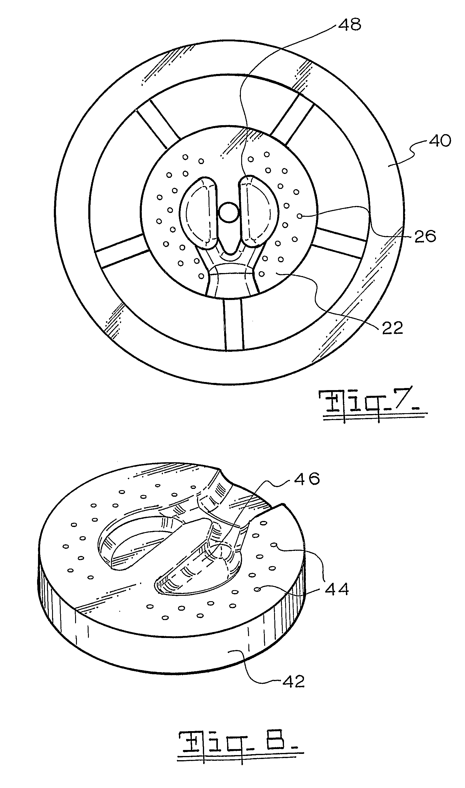
[0022] FIG. 7 is a top plane view of the cavity of FIG. 4;
[0023] FIG. 8 is a perspective view of a molded structure formed by the apparatus of FIG. 1;
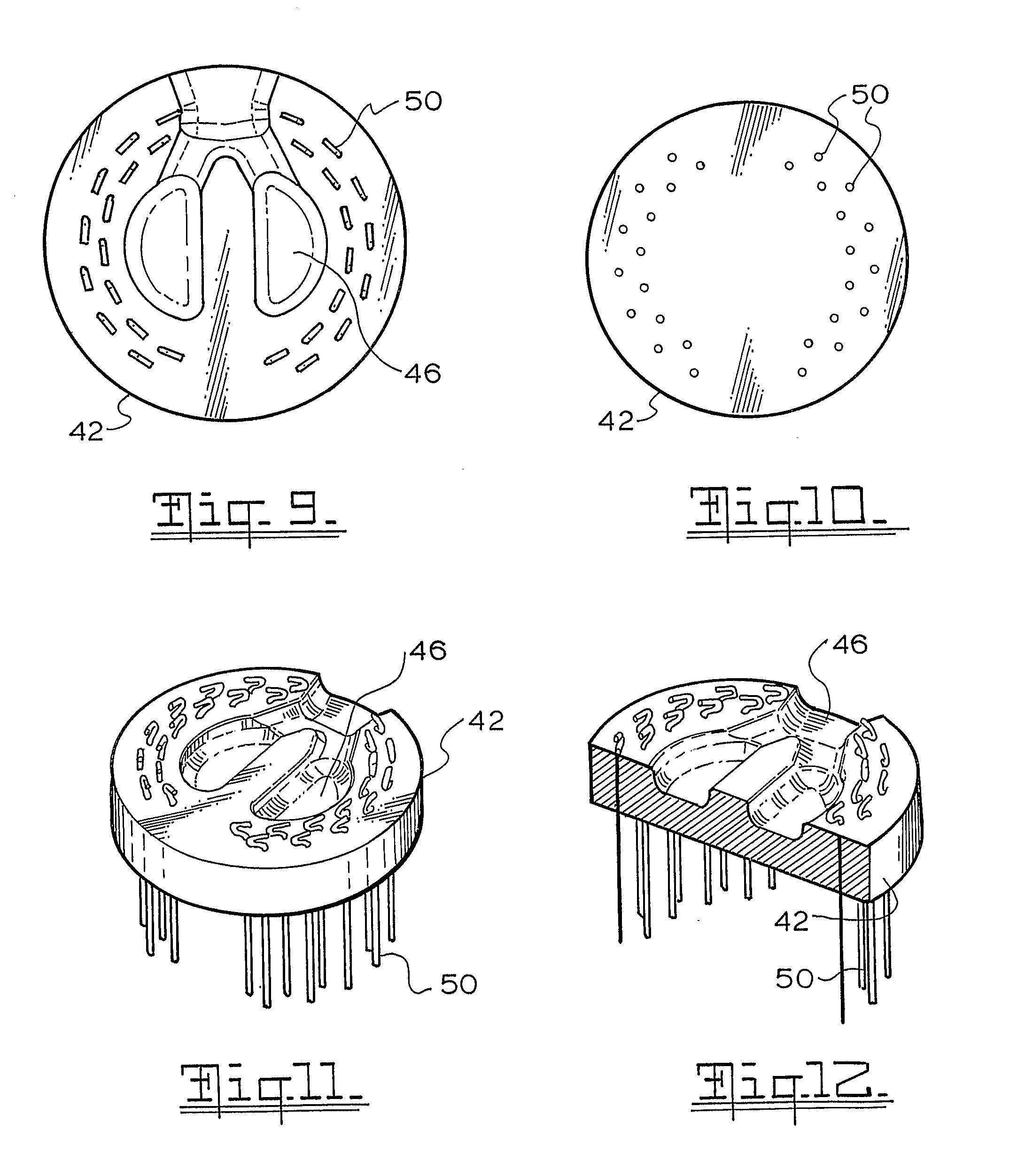
[0024] FIG. 9 is a top plan view of the structure of FIG. 8 having conductive members disposed therein, in accordance with embodiments of the present invention;
[0025] FIG. 10 is a bottom plan view of the structure of FIG. 9;
[0026] FIG. 11 is a perspective view of the structure of FIG. 9; and
[0027] FIG. 12 is a cross-sectional view of the structure of FIG. 11.
DETAILED DESCRIPTION
[0028] Embodiments of the present invention are generally apparatus and methods for forming an insulative structure usable as a component of a feedthrough device. Subsequent to the molding, hermetically sealed feedthroughs are formed in the holes to form a feedthrough device.
[0029] FIGS. 1 and 2 illustrate an exemplary molding apparatus 10 in accordance with embodiments of the present invention. As shown, molding apparatus 10 comprises a housing having an upper portion 12 and a lower portion 14 which meet at a parting line 16. The two portions 12, 14 are arranged to be separable and, in certain embodiments, the upper portion 12 is fixed while the lower portion 14 is moveable.
[0030] As shown, upper r portion 12 carries an injection nozzle 18 via which moldable electrically insulating material, such as ceramic feedstock, may be injected into a mold cavity 22. Injection nozzle 18 is directed towards an open top end 20 of a mold cavity 22 arranged in lower portion 14 having first and second ends. When upper and lower portions 12, 14 are brought together, a sealing member in the form of an o-ring 24 which provides a vacuum seal which allows a negative pressure to be provided i in cavity 22. As such, injection nozzle 18 is able to inject the ceramic feedstock towards cavity 22.
[0031] Housed within lower portion 14 and extending through cavity 22 from the second to the first end are a number of pins 26. As shown in FIG. 5, pins 26 extend beyond parting line 16 into upper portion 12. Upper portion 12 is provided with recesses (not shown) which receive the upper ends of pins 26 when portions 12, 14 are brought together.
[0032] Arranged within cavity 22 is a moveable cavity member 28 which extends across cavity 22 to define a bounded region of cavity 22, referred to as a sub-cavity. Cavity member 28 is initially biased adjacent the first end (ie. adjacent parting line 16) and is configured to move along a path or axis of travel away from the first end. Cavity member 28 has through-holes through which pins 26 are configured to extend. Cavity member 28 is engaged with a spring-loaded carrier 30 which biases cavity member 28 towards parting line 16, as shown in FIG. 4. When cavity member 28 is biased towards parting line 16, referred to as a biased position, member 28 is substantially close to injection nozzle 18 and only a small portion of each pin 26 is exposed.
[0033] When injection nozzle 18 begins injecting the ceramic feedstock, the injected feedstock contacts an upper surface 32 of cavity member 28. Thus, cavity member 28 is positioned adjacent the end of the cavity. The pressure of the injected feedstock causes the cavity member 28 to slide against the spring bias within the cavity 22 and along the length of the pins 26 away from parting line 16. The movement of cavity member 28 away from parting line 16 increases the size of the sub-cavity, i.e. exposes more of cavity 22, and exposes more of the length pins 26 to the injected feedstock. In this manner, the ceramic feedstock gradually fills cavity 22 around the exposed length of pins 26. The gradual exposure of pins 26 by the moving of cavity member 28 prevents damage or deformation of pins 26 due to high injection pressures.
[0034] Cavity member 28 is shown having an axial recess 34 within which is arranged an actuator member 36. Actuator member 36 is arranged to engage a pressure sensor (not shown). With this arrangement, the pressure within the cavity 22 can be monitored. In certain embodiments, the pressure sensor is linked in a closed loop arrangement with a controller for the injection process. As such, precise control of injection pressure and holding pressures within cavity 22 is possible. That is, in this embodiment the output of the pressure sensor is used by an injection controller for controlling injection nozzle 18.
[0035] As shown in FIGS. 4-7, an upper surface 38 of lower portion 14 is provided with a channel or trench arrangement 40 extending from cavity 22. This trench arrangement 40 allows air to be evacuated from cavity 22 as cavity 22 is filled by the injected ceramic feedstock.
[0036] Following the above molding process, the molded electrically insulating structure 42 is ejected from cavity 22 while the ceramic is in a green or unsintered state. Resulting structure 42, as shown in FIG. 8, has a disc shape conforming to the shape of cavity 22. Furthermore, structure 42 has through-holes 44 corresponding to where the pins 26 were arranged within cavity 22, and recesses 46 formed on the upper surface thereof. Recesses 46 correspond to the shape of protrusions 48 on cavity member 28 and provide a convenient place for wires for the final feedthrough device.
[0037] Following the ejection of structure 42 from cavity 22, the finalized feedthrough device may be formed. Referring to FIGS. 9-12, electrically conductive pins 50 are first inserted into holes 44. In certain embodiments, an automated process is implemented to insert conductive pins 50 into holes 44. However, in other embodiments conductive pins may be manually inserted into holes 44. After insertion of conductive pins 50, structure 42 undergoes a de-binding process. An exemplary de-binding process includes a first a water de-binding step, in which the structure 42 is washed over several hours at approximately 40.degree. C., which is followed by a thermal de-binding step conducted at approximately 300.degree. C. over a period of approximately 24 hours. Finally, structure 42 is sintered at relatively high temperatures of, for example, approximately 1600.degree. C. During the sintering step, ceramic structure 42 shrinks and clamps around conductive pins 50, thereby creating a hermetic seal.
[0038] It would be appreciated that a number of different types of ceramic feedstock may be utilized in embodiments of the present invention. However, in embodiments of the present invention, two characteristics influence the choice of suitable ceramic feedstock. A first such characteristic is the ability of a feedstock to shrink during sintering to clamp around conductive pins 50. A second characteristic is the production of a glass phase during sintering which can allow a glaze to form around the conductive pins 50. Two materials having the above characteristics are Alumina and Zirconia. These two materials have a high shrinkage rate, in the range of approximately 16-25 percent. In certain embodiments, composition of the feedstock may include 94-96 percent Alumina (Al.sub.2O.sub.3) or Zirconia (ZrO.sub.2) with a particle size between approximately 0.5 microns to approximately 3 microns. The composition may also include polyethylene which acts as a binder for the composition. Providing trace amounts of Magnesium oxide, Silicon oxide, Zinc oxide or other oxides may stabilize the ceramic and assist in the formation of the glaze.
[0039] If insufficient wall space is provided between conductive pins 50, cracks may form during sintering between the pins 50. As such, as shown in FIGS. 8-12, holes 44 formed in structure 42 for conductive pins 50 may be provided in a staggered configuration to eliminate or substantially reduce the formation of cracks.
[0040] In certain embodiments, methods of the present invention utilize a mold apparatus comprising a housing defining a cavity having an axis extending there through, an injection nozzle disposed at a first end of the cavity, a plurality of pins extending through the cavity along the axis, and a cavity member extending across the cavity substantially orthogonal to the axis so as to form a sub-cavity between the cavity member and the first end of the cavity into which the moldable material is injected, the cavity member having a plurality holes through which the pins extend. In such embodiments, the method comprises: biasing the cavity member such that the member is adjacent the first; and injecting moldable electrically insulative material into the cavity via the nozzle such that the cavity member moves, relative to the pins and the housing, along the axis away from the first end to increase the volume of the sub-cavity as the moldable material is injected.
[0041] In certain embodiments, the method further includes the step of sealing the mold cavity under vacuum pressure before injecting the feedstock. In exemplary embodiments, the method further includes the step expelling air from the cavity as the feedstock is injected.
[0042] In still further embodiments the method includes the step of measuring the pressure within the cavity. In specific such embodiments, the measured pressure is utilized to control the injection of the feedstock.
[0043] The invention described and claimed herein is not to be limited in scope by the specific embodiments herein disclosed, since these embodiments are intended as illustrations, and not limitations, of several aspects of the invention. Any equivalent embodiments are intended to be within the scope of this invention. Indeed, various modifications of the invention in addition to those shown and described herein will become apparent to those skilled in the art from the foregoing description. Such modifications are also intended to fall within the scope of the present invention.
* * * * *
D00000
D00001
D00002
D00003
D00004
D00005
XML
uspto.report is an independent third-party trademark research tool that is not affiliated, endorsed, or sponsored by the United States Patent and Trademark Office (USPTO) or any other governmental organization. The information provided by uspto.report is based on publicly available data at the time of writing and is intended for informational purposes only.
While we strive to provide accurate and up-to-date information, we do not guarantee the accuracy, completeness, reliability, or suitability of the information displayed on this site. The use of this site is at your own risk. Any reliance you place on such information is therefore strictly at your own risk.
All official trademark data, including owner information, should be verified by visiting the official USPTO website at www.uspto.gov. This site is not intended to replace professional legal advice and should not be used as a substitute for consulting with a legal professional who is knowledgeable about trademark law.