Pattern Steamflooding With Horizontal Wells
MENARD; Wendell Peter
U.S. patent application number 12/815001 was filed with the patent office on 2010-12-30 for pattern steamflooding with horizontal wells. This patent application is currently assigned to CONOCOPHILLIPS COMPANY. Invention is credited to Wendell Peter MENARD.
| Application Number | 20100326656 12/815001 |
| Document ID | / |
| Family ID | 43379461 |
| Filed Date | 2010-12-30 |

| United States Patent Application | 20100326656 |
| Kind Code | A1 |
| MENARD; Wendell Peter | December 30, 2010 |
PATTERN STEAMFLOODING WITH HORIZONTAL WELLS
Abstract
Processes and systems comprising a five-spot pattern of multiple horizontal wells for increasing the efficiency of heated vapor-assisted hydrocarbon recovery from subterranean viscous hydrocarbon formations.
| Inventors: | MENARD; Wendell Peter; (Katy, TX) |
| Correspondence Address: |
    ConocoPhillips Company - IP Services Group;Attention: DOCKETING
    600 N. Dairy Ashford, Bldg. MA-1135
    Houston
    TX
    77079
    US
|
| Assignee: | CONOCOPHILLIPS COMPANY Houston TX |
| Family ID: | 43379461 |
| Appl. No.: | 12/815001 |
| Filed: | June 14, 2010 |
Related U.S. Patent Documents
| Application Number | Filing Date | Patent Number | ||
|---|---|---|---|---|
| 61220731 | Jun 26, 2009 | |||
| Current U.S. Class: | 166/272.3 ; 166/57 |
| Current CPC Class: | E21B 43/086 20130101; E21B 43/305 20130101; E21B 43/24 20130101 |
| Class at Publication: | 166/272.3 ; 166/57 |
| International Class: | E21B 43/24 20060101 E21B043/24 |
Claims
1. A process for recovering viscous hydrocarbons from an underground hydrocarbon formation, comprising the following steps: a) drilling a "production unit" comprising three separate and adjacent wellbores into an underground formation containing viscous hydrocarbons; b) extending each of the three wellbores through said formation in a substantially horizontal direction for a distance greater than thirty meters; said horizontal portion of each wellbore being substantially parallel to the other two wellbores in both horizontal and vertical planes; c) inserting a tubular liner into each well comprising periodic sections of liner containing one or more orifices, separated by multiple sections of liner without orifices; d) inserting tubing with a closed end into each wellbore inside of the liner, wherein the tubing contains periodic orifices, and wherein the annular space between the outer wall of the tubing and the inner wall of the liner on either side of each periodic tubular orifice is isolated from the remainder of the wellbore by a device that restricts flow through the annular space; e) injecting heated vapor into the tubing present in the first and third wellbores, such that the vapor enters the formation and reduces the viscosity of the viscous hydrocarbons contained therein; f) collecting hydrocarbons exiting the formation via periodic orifices in the tubular liner present in the second wellbore, wherein the second wellbore utilized for hydrocarbon production is centrally located between injection wellbores one and three when viewed from above, and wherein the second wellbore is approximately equidistant to the two adjacent injection wellbores.
2. The process of claim 1, wherein the periodic orifices in the tubular liners of the three adjacent wellbores comprising a production unit are positioned relative to each other such that when viewed from above, a five-spot pattern is formed, with each collection orifice in the tubular liner of wellbore two being encircled by four substantially equidistant steam injection orifices consisting of two orifices in the tubular liner of wellbore one and two orifices in the tubular liner of wellbore three.
3. The process of claim 2, wherein the three adjacent wellbores comprising a production unit are located in a substantially horizontal plane.
4. The process of claim 2, wherein the third well of a first production unit serves as the first well of a second, adjacent production unit.
5. The process of claim 4, wherein multiple, adjacent production units are drilled to cover the width of an entire formation containing viscous hydrocarbons.
6. The process of claim 2, wherein the multiple periodic liner orifices utilized for either injection of heated vapor or for the production of hydrocarbons comprise a member of the group consisting of mesh screens, wire-wrap screens, perforations or slots.
7. The process of claim 2, wherein prior to production from wellbore two, heated vapor is first injected simultaneously into all wellbores until the viscous hydrocarbons present in the underground formation reach a temperature where recovery of the hydrocarbons as a liquid is possible.
8. The process of claim 2, where the distance between injection points in the five-spot pattern is between 10 and 500 meters.
9. The process of claim 2, where the distance between injection points in the five-spot pattern is between 25 and 300 meters.
10. A system for injecting heated vapor into a formation containing viscous hydrocarbons, and recovering hydrocarbons from the same formation, comprising: a) a "production unit" of three separate and adjacent wellbores drilled into an underground formation containing viscous hydrocarbons; i. wherein each of the three wellbores is drilled through said formation in a substantially horizontal direction for a distance greater than 30 meters; said horizontal portion of each wellbore drilled substantially parallel to the other two wellbores in both horizontal and vertical planes; ii. and wherein the substantially horizontal section of each wellbore is uncased; iii. and wherein the second wellbore is utilized for hydrocarbon production and centrally located between the first and third wellbores when viewed from above; iv. and wherein the first and third wellbores are utilized for injection of steam into the formation; b) tubing with a closed end inserted into each wellbore, wherein said tubing contains periodic orifices, said orifices being selected from the group consisting of slots, perforations, or wire-wrap screens, or wire mesh screens; c) a device that regulates the flow of heated vapor through the annulus formed between the injection tubing and the liner wall on either side of each periodic injection orifice; d) a device for regulating the flow of hydrocarbons through the annulus formed between the production tubing and the liner wall on either side of each periodic production orifice.
11. The system of claim 10, wherein said device for regulating the flow of hydrocarbons comprises a device selected from the group consisting of mechanically-set packers, hydraulically-set packers, inflatable packers or seals.
12. The system of claim 10, wherein the periodic orifices of the three adjacent wellbores comprising a production unit are positioned relative to each other such that when viewed from above, a five-spot pattern is formed, with each collection orifice in the liner of wellbore two being encircled by four substantially equidistant steam injection orifices consisting of two orifices in the liner of wellbore one and two orifices in the liner of wellbore three.
13. The system of claim 12, wherein the three adjacent wellbores comprising a production unit are located in a substantially horizontal plane.
14. The system of claim 12, wherein the third well of a first production unit serves as the first well of a second, adjacent production unit.
15. The system of claim 14, wherein multiple, adjacent production units are drilled to cover the width of an entire formation containing viscous hydrocarbons.
16. The system of claim 12, wherein the multiple periodic liner orifices in each well utilized for either the injection of heated vapor or the production of viscous hydrocarbons comprise mesh screens, wire-wrap screens, perforations, or slots.
17. The system of claim 12, wherein prior to production from wellbore two, heated vapor is first injected simultaneously into all wellbores until the viscous hydrocarbons present in the underground formation reach a temperature where recovery of the hydrocarbons as a liquid is possible.
18. The system of claim 12, where the distance between injection points in the five-spot pattern is between 10 and 500 meters.
19. The system of claim 12, where the distance between injection points in the five-spot pattern is between 25 and 300 meters.
Description
FIELD OF THE DISCLOSURE
[0001] The invention generally relates to improved methods and apparatus for the recovery of viscious hydrocarbons from underground formations. More specifically, it relates to methods and apparatus for enhancing the recovery of viscous hydrocarbons from a subterranean formation by steamflooding utilizing multiple horizontal wells.
BACKGROUND
[0002] Steam and combustion processes have often been employed to heat underground formations containing viscous hydrocarbon deposits, thereby lowering the viscosity of the petroleum contained within and providing a driving force to produce these viscous hydrocarbons from a well. Steam injection methodology was originally conducted using vertical wells. U.S. Pat. No. 5,014,784 describes a series of vertical injection wells in conjunction with adjacent vertical production wells. U.S. Pat. Nos. 4,598,770, 4,727,937 and 5,957,202 describe multiple vertical injection wells in conjunction with adjacent horizontal production wells. However, viscous hydrocarbon recovery using vertical wells requires a high well density (or number of wells per unit area), to effectively recover the hydrocarbons in a timely and efficient manner. Vertical well densities of 640 wells per square mile or more have been used in the recovery of viscous hydrocarbons in California.
[0003] The use of horizontal drilling technology for viscous hydrocarbon recovery is now well-established. An increased area of contact between the wellbore and the formation can be achieved by drilling wells with a substantially horizontal component (typically, 300 to 2,000 meters, compared to 5-30 meters for a typical vertical well). This large contact area allows viscous hydrocarbon formations to be developed and recovered by far fewer horizontal wells than are required in a vertical well development. The final result is higher oil production rates from fewer wells. Similarly, in a steam injection process, a single horizontal injection well can deliver more steam over a wider area of the viscous oil reservoir than many vertical wells, thereby heating the reservoir more efficiently.
[0004] Some older viscous hydrocarbon recovery methods involve injection of steam through either orifices in the casing or the tubing, such as multiple sections of tubing containing multiple, parallel slots (known as slotted liners), with single horizontal wellbores serving as both the injection and production well. This is commonly known as the "huff and puff" technique. Unfortunately, these single wellbore techniques do not allow simultaneous steam injection and hydrocarbon production. Consequently, more recently developed methodologies involve the use of multiple horizontal wells. U.S. Pat. No. 4,574,884 describes a method for drilling multiple substantially parallel horizontal wells, where fluid communication is established between the wells and injection of steam into one well provides the driving force for production of hydrocarbons from an adjacent well. U.S. Pat. No. 4,700,779 describes a more elaborate method for drilling at least four substantially parallel horizontal wells, followed by injection and/or production from different wells within the group. What is lacking in these methods is a way to effectively control the entry of steam into the formation, thereby maximizing the overall percentage of hydrocarbons recovered.
[0005] As the viscous hydrocarbons within a formation are heated, gravity generally causes the downward flow of these heated hydrocarbons within the formation. Some methodologies for recovering viscous hydrocarbons incorporate this phenomenon, known as "steam-assisted gravity drainage" (SAGD). U.S. Pat. No. 4,577,691 describes drilling a series of parallel horizontal wells that are vertically-spaced, with each well designed such that it is simultaneously possible to both inject steam and produce hydrocarbons. Initially, steam is injected through one or more upper wells, and heated viscous hydrocarbons are recovered from progressively lower wells. U.S. Pat. No. 5,244,041 and U.S. Pat. App. 2007/0295499A1 describe methods that utilize SAGD by drilling multiple pairs of horizontal wells, with each pair spaced vertically. These references also describe the injection of steam to induce lateral flow of viscous hydrocarbons between adjacent well pairs. Similarly, U.S. Pat. No. 6,257,334 describes a pair of vertically-spaced horizontal wells, along with a single, laterally offset horizontal well used for injection. U.S. Pat. Nos. 4,850,429 and 5,803,171 describe methods that utilize SAGD by drilling a group of parallel horizontal wells, with adjacent wells alternating between higher and lower depths within the hydrocarbon-bearing formation. Steam is initially injected into the upper wells, and production initiated in the lower, adjacent wells.
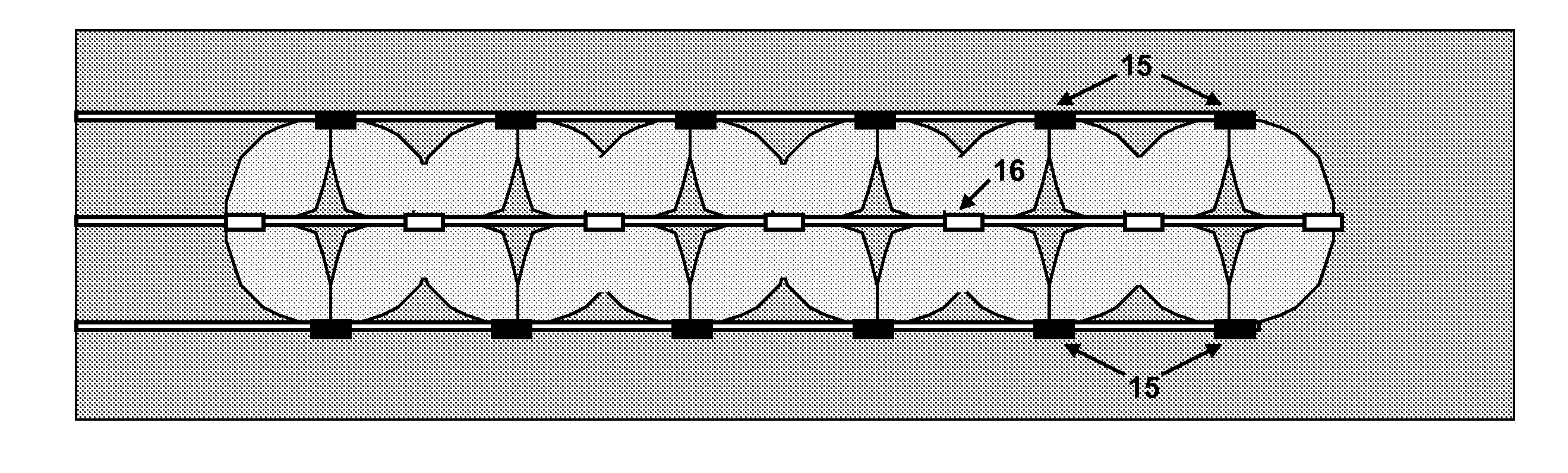
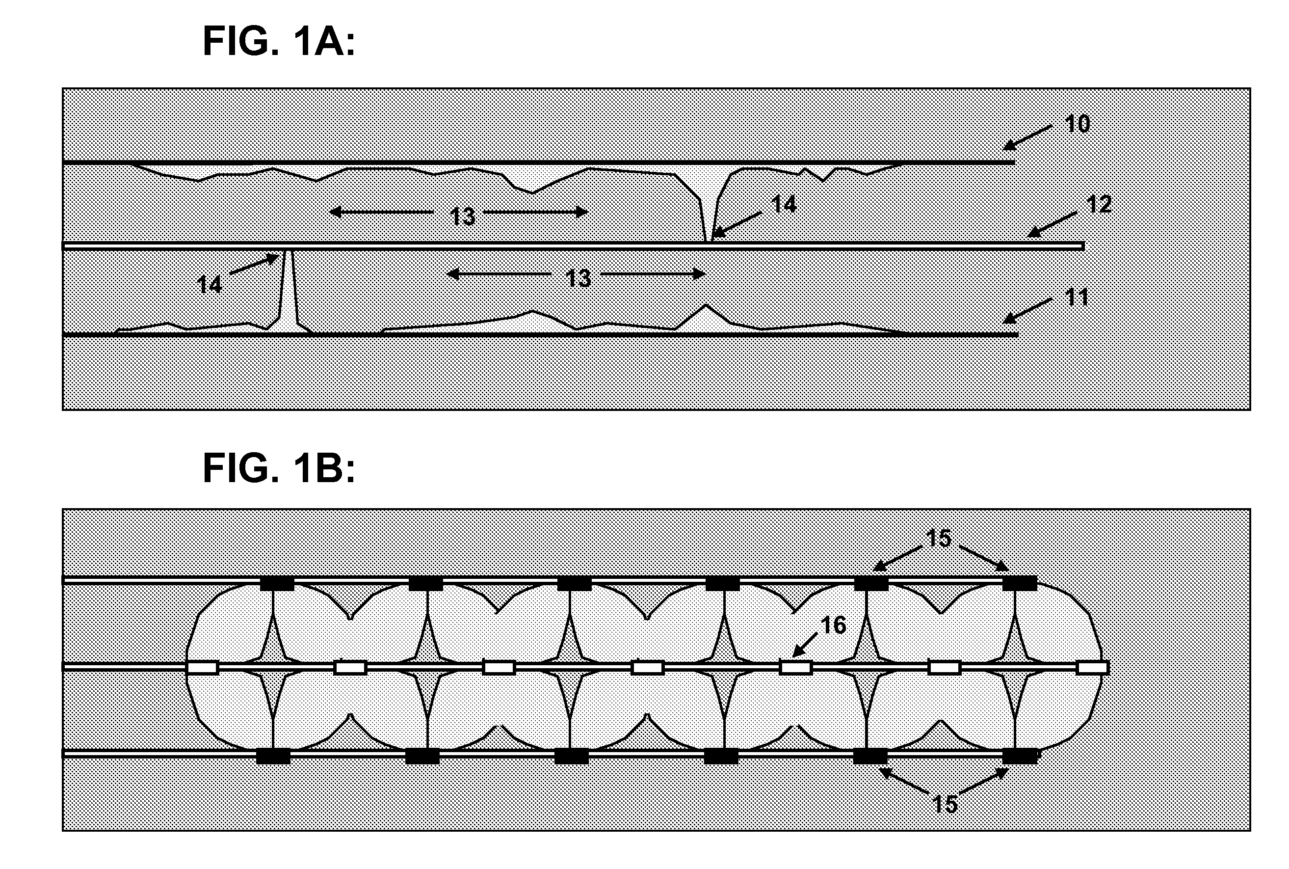
[0006] Premature breakthrough of steam is a problem that has plagued multiple well steam injection methodologies since their inception. While this problem is a nuisance in vertical well pattern steam flooding, it can be catastrophic in horizontal well steamflooding. In the case of vertical well steam flooding, there are many wells (injection wells and production wells), and the flow rate of each well can be controlled independently at the well head, so as to balance the patterns and achieve maximum oil production with minimum of steam production. This level of control at the surface is not usually possible in the case of horizontal well steam flooding, where each horizontal well is akin to a line of many vertical wells with only one common well head. This makes it highly desirable to control both the rate and distribution of steam injection along horizontal injector well bores, as well as production distribution of viscous hydrocarbons along horizontal producer well bores. Consider pair of 1000-meter long horizontal wells, one serving as a production well and the other an injection well. If steam from the injection well breaks through to the production well prematurely, (i.e., early in the viscous hydrocarbon recovery effort) it is likely that the majority of the viscous hydrocarbons between the two wells will remain unrecovered because the steam would continue to flow preferentially along this same path, leaving the majority of the formation unexposed to the steam, and therefore unheated (FIG. 1A). U.S. Pat. No. 5,141,054 discusses a method to promote uniform steam injection distribution along the length of a horizontal steam injection well using a limited number of perforations. Spacing a limited number of perforations along the injection well bore limits the amount of steam that can be injected in any one location along the well bore--the perforation acts as a choke that limits the flow to the path of least resistance, thereby allowing the steam to exit other perforations along the wellbore instead of all exiting in one place. However, while this method addresses the uniform distribution of steam into the formation from an injection well, it does not address regulating the entry of mobilized viscous hydrocarbons into the production well. This is an important additional consideration if the efficiency of viscous hydrocarbon recovery is to be maximized (FIG. 1B).
[0007] Concern over the environmental impact of subterranean hydrocarbon recovery has grown recently, especially in regards to fragile biomes such as the north slope region of Alaska. Thus, there is an increased societal demand for drilling and recovery methodologies that minimize impact on the environment. U.S. Pat. No. 5,014,784 discusses methods for recovering viscous oil through the use of multiple wells. The methods involve drilling multiple vertical steam injection wells, then producing viscous hydrocarbons from adjacent vertical wells. U.S. Pat. No. 4,598,770 combines the use of vertical wells for steam injection with recovery from multiple adjacent horizontal production wells. The end result of these strategies is a relatively large land surface "footprint" required for drilling and recovery of hydrocarbons, which is often considered unsightly and overly damaging to the local ecosystem. Any reduction in the surface "footprint" required for hydrocarbon drilling and recovery operations would certainly be of benefit to the environment and may facilitate the exploration for hydrocarbons in areas of the Earth where the local ecosystem might be deemed too fragile to explore using conventional techniques.
[0008] What is needed are methods that maximize recovery of viscous hydrocarbons from underground formations by simultaneously promoting an even, regulated distribution of steam into a given viscous hydrocarbon-producing reservoir and an even, regulated distribution of produced fluids from the same reservoir. Simultaneously, these methods must minimize the environmental impact of land-based oil drilling and production operations, given the fragile nature of the natural environment where a significant percentage of this activity currently takes place.
BRIEF DESCRIPTION
[0009] The present invention describes a method for maximizing the recovery of viscous hydrocarbons from an underground formation using steam injection. A "production unit" comprising at least three adjacent horizontal wellbores is drilled into a formation containing viscous hydrocarbons. In certain embodiments, said three wells all contain a substantially horizontal component extending for at least 30 meters, In certain embodiments, the three wells are substantially parallel to each other when viewed from above. In certain embodiments, the three wells are located near the bottom of the hydrocarbon-producing formation. In certain embodiments, the central production well is located in substantially the same horizontal plane as the two outer steam injection wells.
[0010] In certain embodiments of the current invention, pressurized steam is passed directly into the formation via periodic orifices in the liner of the two injection wells. On either side of each periodic orifice within the wellbore, a device is placed that can restrict steam flow through the annular space between the tubing and the wellbore wall. These flow restriction devices may comprise mechanical or hydraulically-actuated packers, inflatable packers, or other types of seals that can effectively restrict the point of steam entry into the formation to relatively small periodic regions comprising less than twenty-five percent of the length of the entire wellbore.
[0011] The injected steam enters the formation and transfers heat to the viscous hydrocarbons in the formation, lowering the viscosity of the hydrocarbons and providing a force to cause migration of the hydrocarbons in a generally lateral and/or downward direction towards the periodic inlet orifices in the central production well located between the two injection wells (when viewed from above). In certain embodiments, the periodic orifices in the injection and production wells are spaced in a five-spot pattern comprising a central production orifice, surrounded by four injection orifices (two orifices provided by each adjacent injection well) that are approximately equidistant from the central production orifice. In preferred embodiments, the four injection orifices are also approximately equidistant from each other. This five-spot pattern arrangement is designed to maximize the time that steam injection into the formation can continue before steam breakthrough to the production well.
[0012] The disclosure provided herein describes a method for recovering viscous hydrocarbons from a subsurface formation that increases the efficiency of hydrocarbon recovery while also minimizing environmental impact. In certain preferred embodiments, the production process described herein requires far fewer wells than a viscous hydrocarbon recovery process utilizing vertical wells for periodic steam injection. Thus, the ground surface "footprint" required for hydrocarbon recovery is minimized, as well as the resultant environmental impact.
[0013] For the purposes of this disclosure, the term "liner" describes a cylindrical pipe inserted into a wellbore for maintaining wellbore integrity, and controlling production of sand and sediment along with the produced hydrocarbons; "Liner" also facilitates the selective distribution of steam into the formation, and selective recovery of hydrocarbons via periodic orifices in the liner.
[0014] For the purposes of this disclosure, the term "tubing" is defined as a cylindrical tubing that is inserted inside of the liner and either facilitates transport of steam into the formation, or transport of hydrocarbons out of the well.
[0015] For the purposes of this disclosure, the term "wellbore" is synonymous with "well", as both terms describe a hole drilled into the earth at any angle using conventional drilling equipment.
[0016] For purposes of this disclosure, the terms "uncased well" or "openhole completion" are defined as a wellbore in which the portion of the wellbore utilized for production is not protected by a conventional well casing. In most horizontal wells, this area represents the substantially horizontal section of the well that penetrates the formation containing recoverable hydrocarbons.
[0017] For the purposes of this disclosure, the terms "steamflood" or "steamflooding" are synonymous with "steam injection", as all of these terms describe a technique by which steam is injected into an underground formation to cause increased flow of viscous hydrocarbons.
[0018] For the purposes of this disclosure, the term "five-spot pattern" is synonymous with any pattern which when viewed from above, has five distinct points, with a central point surrounded by four points that are approximately equidistant from the central point, and approximately equidistant from each other.
[0019] For the purposes of the current disclosure, the term "substantially" is defined as a being as close to the desired outcome as is feasible utilizing currently available technology.
[0020] For purposes of the current disclosure, the term "viscous hydrocarbon" is synonymous with the terms "heavy oil", "bitumen", "tar", "tar sands" or "asphaltic substance".
[0021] For purposes of the current disclosure, the term "hydrocarbon-bearing formation" is synonymous with any underground formation containing hydrocarbons, including viscous oil.
[0022] For purposes of the current disclosure, the term "horizontal well" is synonymous with any well that extends underground and has a substantially horizontal component extending greater than 30 meters.
[0023] In certain embodiments, the current disclosure describes a process for recovering viscous hydrocarbons from an underground hydrocarbon formation, comprising the steps of: a) drilling a "production unit" comprising three separate and adjacent wellbores into an underground formation containing viscous hydrocarbons; b) extending each of the three wellbores through said formation in a substantially horizontal direction for a distance greater than thirty meters; said horizontal portion of each wellbore being substantially parallel to the other two wellbores in both horizontal and vertical planes; c) inserting a tubular liner into each well comprising periodic sections of liner containing one or more orifices, separated by multiple sections of liner without orifices; d) inserting tubing with a closed end into each wellbore inside of the liner, wherein the tubing contains periodic orifices, and wherein the annular space between the outer wall of the tubing and the inner wall of the liner on either side of each periodic tubular orifice is isolated from the remainder of the wellbore by a device that restricts flow through the annular space; e) injecting heated vapor into the tubing present in the first and third wellbores, such that the vapor enters the formation and reduces the viscosity of the viscous hydrocarbons contained therein; and f) collecting hydrocarbons exiting the formation via periodic orifices in the tubular liner present in the second wellbore, wherein the second wellbore utilized for hydrocarbon production is centrally located between injection wellbores one and three when viewed from above, and wherein the second wellbore is approximately equidistant to the two adjacent injection wellbores. In certain embodiments, the three adjacent wellbores comprising a production unit may be placed in a substantially horizontal plane.
[0024] The current disclosure also describes a system for injecting steam into a formation containing viscous hydrocarbons, and recovering hydrocarbons from the same formation, comprising: a) a "production unit" of three separate and adjacent wellbores drilled into an underground formation containing viscous hydrocarbons; wherein each of the three wellbores is drilled through said formation in a substantially horizontal direction for a distance greater than 30 meters; said horizontal portion of each wellbore drilled substantially parallel to the other two wellbores in both horizontal and vertical planes; and wherein the substantially horizontal section of each wellbore is uncased; and wherein the second wellbore is utilized for hydrocarbon production and centrally located between the first and third wellbores when viewed from above; and wherein the first and third wellbores are utilized for injection of steam into the formation; b) tubing with a closed end inserted into each wellbore, wherein said tubing contains periodic orifices, said orifices being selected from the group consisting of slots, perforations, or wire-wrap screens, or wire mesh screens; c) a device that regulates the flow of steam through the annulus formed between the injection tubing and the liner wall on either side of each periodic injection orifice; d) a device for restricting the flow of hydrocarbons through the annulus formed between the production tubing and the liner wall on either side of each periodic production orifice.
[0025] In certain embodiments of both the process and system, the periodic orifices in the tubular liners of the three adjacent wellbores comprising a production unit are positioned relative to each other such that when viewed from above, a five-spot pattern is formed, with each collection orifice in the tubular liner of wellbore two being encircled by four substantially equidistant steam injection orifices consisting of two orifices in the tubular liner of wellbore one and two orifices in the tubular liner of wellbore three. In certain embodiments of the process and system, the three adjacent wellbores comprising a production unit are placed in a substantially horizontal plane.
[0026] In certain embodiments of both the process and system, the distance between the periodic orifices in the five-spot pattern is between 10 and 500 meters, and may be between 25 and 300 meters. In certain embodiments of the process and system, the third well of a first production unit serves as the first well of a second, adjacent production unit, and multiple adjacent production units are drilled to cover the width of an entire formation containing viscous hydrocarbons.
[0027] In certain embodiments of both the process and system, the periodic liner orifices in each tubular liner utilized for the injection of vapor may comprise a member of the group consisting of mesh screens, wire-wrap screens, perforations or slots. Similarly, the periodic liner orifices in the second well utilized for production of hydrocarbons may comprise a member of the group consisting of mesh screens, wire-wrap screens, perforations or slots. In certain embodiments of the method and system, steam is first injected simultaneously into all wellbores prior to production from wellbore two, until the viscous hydrocarbons present in the underground formation reach a temperature where recovery of the hydrocarbons as a liquid is possible.
[0028] In certain embodiments of the process, the annular space between the outer wall of the tubing and the inner wall of the liner on either side of each periodic orifice in the liner is isolated from the remainder of the wellbore by a device that restricts flow through the annular space. The device may comprise a member of the group consisting of mechanically-set packers, hydraulically-set packers, inflatable packers, or seals. In injection wells, the device serves to restrict the flow of heated vapor down the annulus, while in production wells, the device serves to restrict the flow of recovered heated viscous hydrocarbons down the annulus.
BRIEF DESCRIPTION OF THE DRAWINGS
[0029] Advantages of the present invention will become apparent to those skilled in the art with the benefit of the following description and upon reference to the accompanying drawings.
[0030] FIG. 1A shows a typical result of an uncontrolled steamflooding process utilizing multiple adjacent horizontal wells. The unregulated entry of steam into the formation via the injector wells (top and bottom) often results in premature breakthrough of steam to the production well (central), thereby limiting recovery of the remaining heavy oil located between the wells. FIG. 1B shows an expected drainage of heavy oil from a formation utilizing an embodiment of the current invention. Regulated, periodic entry of steam into the formation and regulated periodic recovery points function together to maximize the recovery of heavy oil prior to steam breakthrough at the production well.
[0031] FIG. 2 shows examples of conventional steam injection methodologies, wherein vertical injection wells are combined with vertical production wells (FIG. 2A), vertical injection wells are combined with horizontal production wells (FIG. 2B), or horizontal injection wells are combined with established vertical production wells (FIG. 2C).
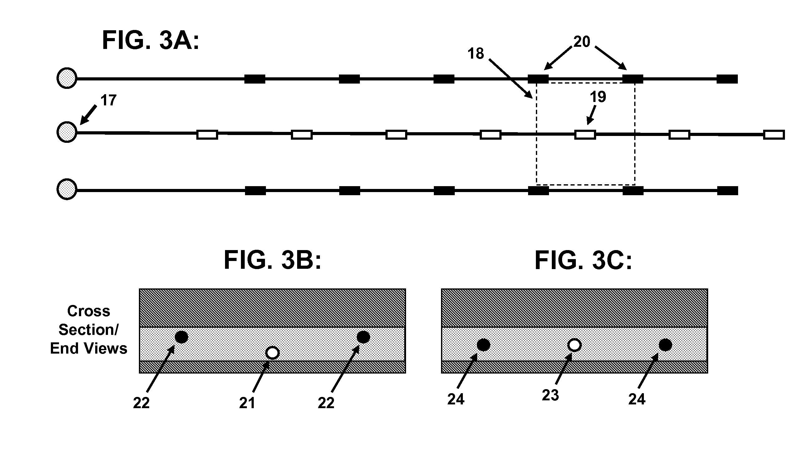
[0032] FIG. 3A is a schematic overhead view of an embodiment of the current invention, illustrating a "production unit" comprising three adjacent horizontal wells, and showing the five-spot pattern established between each orifice in a production well and the surrounding four injection points supplied by the adjacent injection wells. FIG. 3B is a schematic cross-sectional end view of an embodiment of the current invention showing the positioning of the adjacent horizontal wells of a "production unit" at different depths within the hydrocarbon-bearing formation. FIG. 3C is a schematic end-view showing the positioning of the adjacent horizontal wells of a "production unit" in substantially the same horizontal plane within the hydrocarbon-bearing formation.
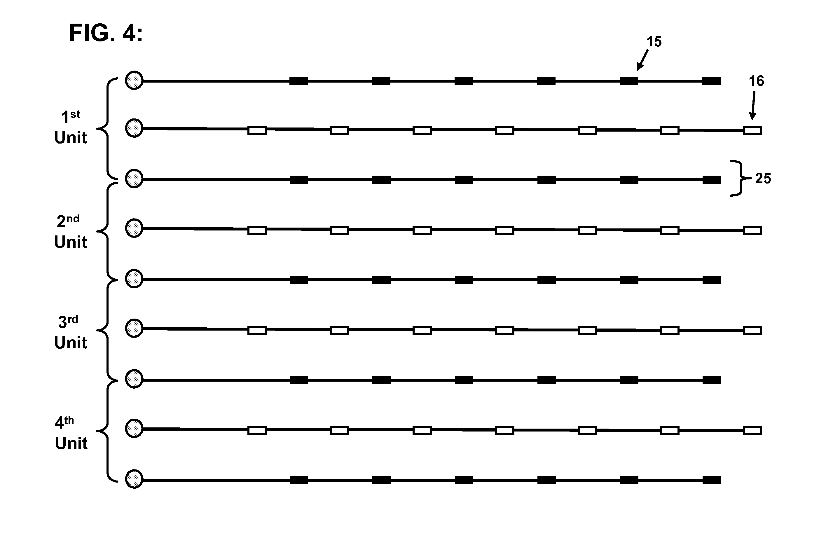
[0033] FIG. 4 is a schematic view of an embodiment of the current invention, showing adjacent, overlapping "production units" wherein the third well of the first "production unit" simultaneously serves as the first well of the second "production unit".
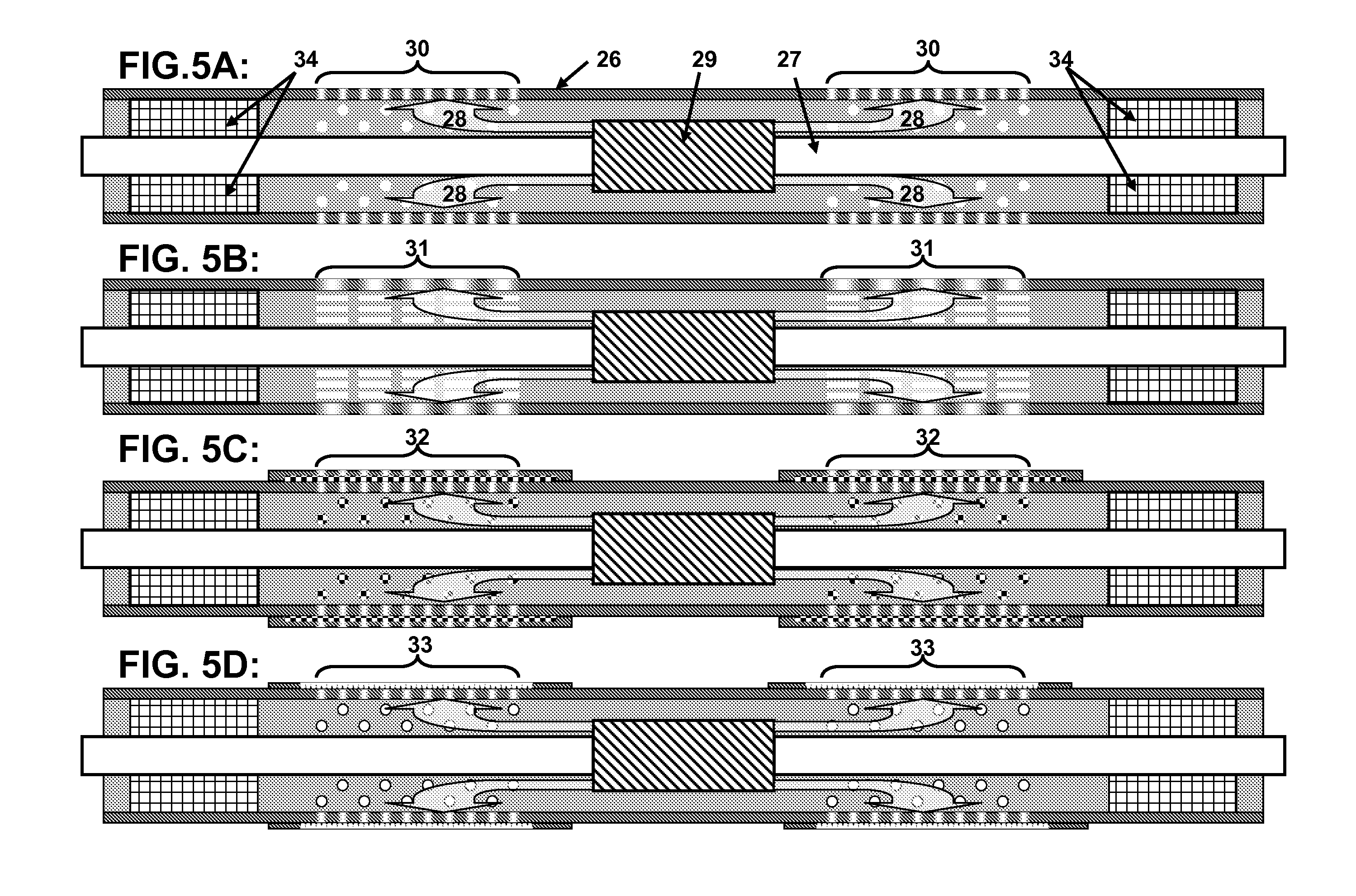
[0034] FIG. 5 is a close-up schematic view of an embodiment of the current invention, wherein steam is distributed downhole via a segment of perforated liner (FIG. 5A), slotted liner (FIG. 5B), mesh screen (FIG. 5C), or wire-wrap screen (FIG. 5D), wherein the annular space between the outer wall of the tubing and the inner wall of the liner on either side of each periodic tubular orifice is isolated by a device that restricts flow through the annular space (packers are shown).
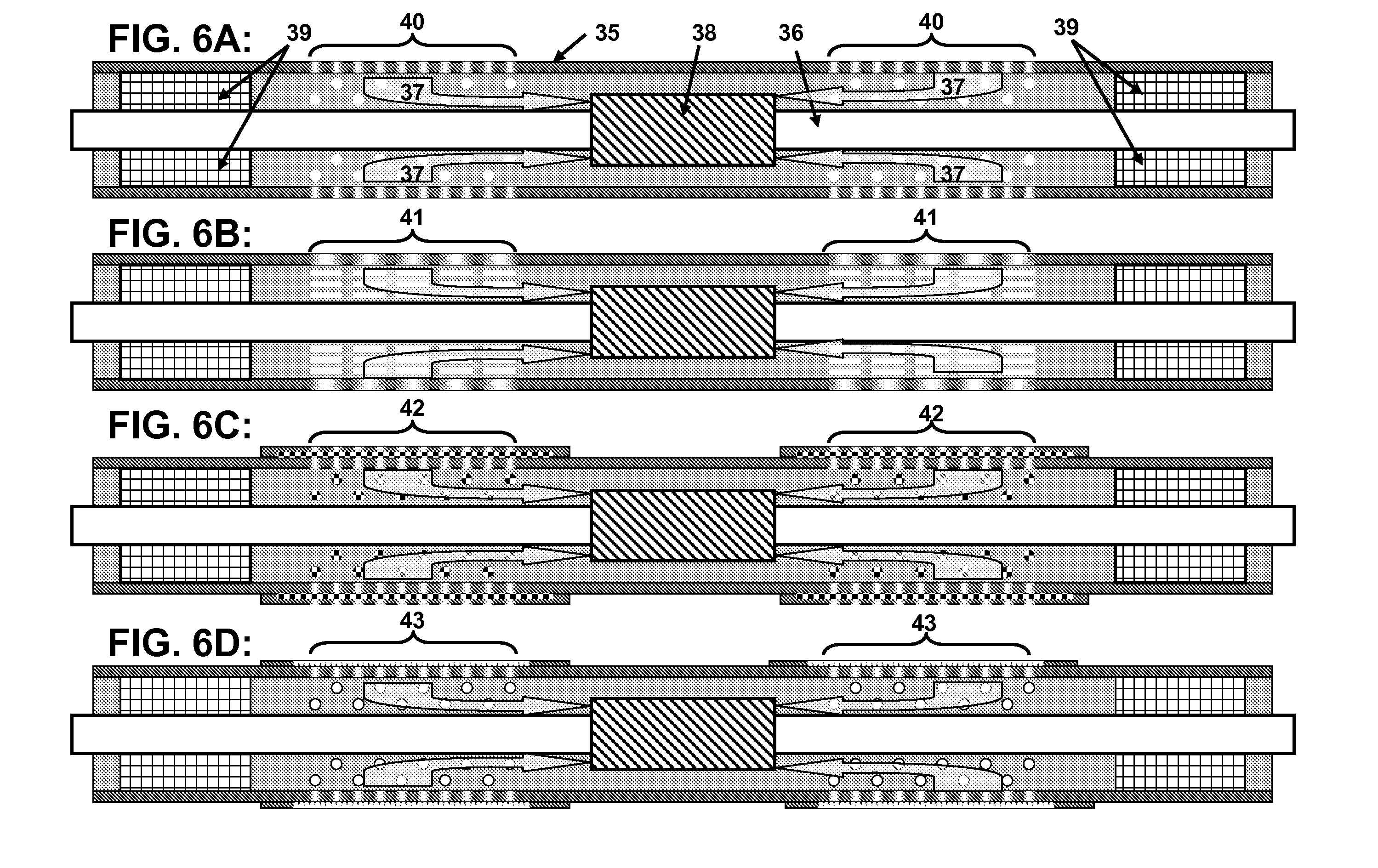
[0035] FIG. 6 is a close-up schematic view of an embodiment of the current invention, wherein hydrocarbons are collected at an orifice in the liner of a production well via a segment of perforated liner (FIG. 6A), slotted liner (FIG. 6B), mesh screen (FIG. 6C), or liner with a wire-wrap screen (FIG. 6D), wherein the annular space between the outer wall of the tubing and the inner wall of the liner on either side of each periodic tubular orifice is isolated by a device that restricts flow through the annular space (packers are shown).
[0036] While the invention is susceptible to various modifications and alternative forms, specific embodiments thereof are shown by way of example in the drawings. The drawings may not be to scale. It should be understood that the drawings and their accompanying detailed descriptions are not intended to limit the scope of the invention to the particular forms or embodiments depicted, but rather, the intention is to cover all modifications, equivalents and alternatives falling within the spirit and scope of the present invention as defined by the appended claims.
DETAILED DESCRIPTION
[0037] A typical, uncontrolled steamflooding process utilizing multiple adjacent horizontal wells is depicted in FIG. 1A. The unregulated entry of steam into the formation via the injector wells (10, 11) often results in premature breakthrough of steam to the central production well (12), thereby limiting recovery of the heavy oil located between the wells (13). FIG. 1B shows a hypothetical drainage pattern of heavy oil from a formation utilizing an embodiment of the current invention. Regulated, periodic entry of steam into the formation (15) and regulated periodic recovery points (16) function together to maximize the recovery of heavy oil prior to steam breakthrough at the production well.
[0038] FIG. 2 depicts examples of conventional steam injection methodologies. In FIG. 2A vertical injection wells (black triangles) are combined with vertical production wells (open circles). In FIG. 2B, vertical injection wells (open triangles) are combined with horizontal production wells (solid black lines). Finally, in FIG. 2C, a horizontal injection well (solid black line) is combined with two established vertical production wells (open circles).
[0039] The disclosure provided herein comprises a process and system for heated vapor-assisted recovery of viscous hydrocarbons from a subsurface formation. FIG. 3A depicts an embodiment of the current invention from an overhead view, and illustrates a "production unit" consisting of three adjacent, parallel, and substantially co-extensive horizontal wells. Each well has a well head (17) and is drilled downward through the overburden and into a formation containing viscous hydrocarbons, whereupon the direction of the drilling is altered using established directional drilling technology until the direction of drilling is substantially horizontal. The wellbores are extended in a substantially horizontal direction through the hydrocarbon-bearing formation for a distance of between 30 and 5,000 meters. The periodic orifices in the liner of the injection and production wells are preferably spaced in a five-spot pattern that centers around each inlet orifice in the production well. The perimeter of the "five-spot" pattern is outlined by a dashed line (18), and comprises a central production orifice (19) surrounded by four injection orifices (20) (i.e., two orifices present in the liner of each adjacent injection well [20]) that are approximately equidistant from the central production well orifice (19). In certain preferred embodiments, these four surrounding injection orifices are also approximately equidistant from each other.
[0040] In certain embodiments, pressurized steam is passed directly into the formation via periodic orifices in the liner of the two outer wells of the "production unit". The injected steam enters the formation and transfers heat to the viscous hydrocarbons in the formation, lowering the viscosity of the hydrocarbons and providing a force to cause migration of the hydrocarbons in a generally lateral and/or downward direction towards the periodic inlet orifices in the central production well located between the two injection wells. The five-spot pattern arrangement, in combination with the restricted entry of steam from the injection orifices into the formation, is designed to maximize the time that steam injection into the formation can continue before steam breaks through to an orifice on the production well.
[0041] In certain embodiments, the distance between wells in the five-spot pattern may range between 10-500 meters, in other embodiments may range between 25-300 meters, and in still other embodiments may range between 50-200 meters. In general, the relationship of the distance between injection orifices and the central production orifice is defined by the Pythagorean theorem. For example, if the distance between injection wells is set at 100 meters, the distance between each injection well and the central production well is equal to the length of the hypotenuse of a right triangle with two sides, each 50 meters in length. In this example, the length of the hypotenuse equals the square root of (50.sup.2+50.sup.2), or 70.71 meters.
[0042] FIG. 3B depicts a cross-sectional end view of one embodiment of the current invention, wherein the central production well (21) of the "production unit" is located at a lower depth than the adjacent injection wells (22). FIG. 3C depicts a cross-sectional end view of one embodiment of the current invention, wherein the central production well (23) of the "production unit" is located at substantially the same depth in the formation as the adjacent injection wells (24).
[0043] In certain embodiments, a "production unit" consisting of three wells may effectively overlap with an adjacent production unit. FIG. 4 illustrates that the third well of a first production unit (25) may simultaneously serve as the first injection well of an adjacent production unit. Subsequent additional production units may be extended laterally from a first production unit in this overlapping manner in order to cover an entire formation containing viscous hydrocarbons, thereby increasing the efficiency of hydrocarbon recovery.
[0044] The first and third wells of the "production unit" are injection wells, utilized for injecting steam under pressure into the formation (FIG. 5). Liner containing periodic orifices is inserted into the injection wellbores (26), followed by the insertion of tubing (27) containing periodic orifices that are placed in sufficiently close proximity to the periodic orifices in the liner to facilitate the passage of steam (28). The steam is injected down the tubing, exiting at least one flow regulator (29), then entering the formation via one or more adjacent periodic liner orifices located in close proximity to the flow regulator (29). In certain embodiments, these sections of liner containing one or more orifices are placed between multiple sections of liner without any openings (i.e., blank pipe), so as to regulate the injection of steam into the formation in such a way as to prevent steam breakthrough to the production well. In certain embodiments where wells traverse stable formations, the periodic orifices in the liner may comprise perforations (30) (FIG. 5A) instead of slotted liner (31) (FIG. 5B). In certain embodiments where infiltration of sediment and sand from the formation may interfere with injection, the periodic liner orifices may comprise wire-mesh screens (32) (FIG. 5C) or wire-wrapped screens (33) (FIG. 5D).
[0045] Adjacent to each flow regulator and one (or more) periodic liner orifice(s), the annular space between the outer wall of the tubing and the inner wall of the liner on either side of each periodic tubular orifice is isolated from the remainder of the wellbore by a device that restricts flow through the annular space (34) (FIGS. 5A-D) to prevent unregulated flow of heated vapor down the annulus. These devices may comprise mechanically or hydraulically-actuated packers, inflatable packers, or other types of seals that can largely prevent the unregulated passage of heated vapor down the annulus. This system acts to restrict the entry of steam into the formation to specific periodic openings in the liner.
[0046] The second well of each "production unit" is a production well (FIG. 6), utilized for recovery of hydrocarbons mobilized as a consequence of heated vapor entering the formation through injection wells one and three. Liner containing periodic orifices is inserted into the production wellbore (35) followed by the insertion of tubing (36) containing periodic orifices that are placed in sufficiently close proximity to the periodic orifices in the liner to facilitate the passage of mobilized viscous hydrocarbons (37) first into the liner, then into a periodic orifice in the tubing (38) for recovery. On either side of each periodic tubing orifice, a device is placed to restrict steam flow through the annular space between the tubing and the liner wall (39). These flow restriction devices may comprise mechanically or hydraulically-actuated packers, inflatable packers, or other types of seals that restrict the passage of steam down the annulus. This system restricts hydrocarbon recovery from the formation to specific periodic openings in the liner, thereby increasing the percentage of total hydrocarbons recovered from the formation prior to breakthrough of injected, heated vapor at the production well (35).
[0047] In certain embodiments, the sections of liner in a production well containing one or more periodic orifices are placed between multiple sections of liner without any openings (i.e., blank pipe), so as to regulate the recovery of hydrocarbons from the formation. In certain embodiments where wells traverse stable formations, the periodic orifices in the liner may comprise perforations (40) (FIG. 6A) instead of slotted liner (41) (FIG. 6B). In certain embodiments where infiltration of sediment and sand from the formation may interfere with injection, the periodic liner orifices may comprise wire-mesh screens (42) (FIG. 6C) or wire-wrapped screens (43) (FIG. 6D).
[0048] In certain embodiments of the current invention, pressurized steam is passed into an underground formation containing viscous hydrocarbons via periodic orifices in the liner of the injection wells. The injected steam enters the formation and transfers heat to the viscous hydrocarbons in the formation, thereby lowering the viscosity of the hydrocarbons and also providing a force to assist migration of mobilized hydrocarbons in a generally lateral and/or downward direction towards the periodic inlet orifices in the central production well. The quality and quantity of steam to be injected is based upon both the relative porosity of the formation and the relative viscosity of the hydrocarbons contained within the formation. These variables also affect the optimal spacing between the orifices comprising the five-spot pattern. The optimal spacing of orifices and quantity of steam to be injected depends on several factors related to the hydrocarbons (mainly its viscosity), the hydrocarbon-bearing formation (its thickness, porosity, permeability, temperature, and mechanical properties), the wells (length, diameter, completion, and artificial lift equipment), and the facilities (rate, temperature, and pressure limitations). In general, to maintain the five-spot pattern as described, the distance between periodic orifices in the liner of a given well would be approximately the same as the distance between adjacent horizontal wells in the "production unit".
[0049] The process described herein recovers viscous hydrocarbons from a subsurface formation with increased efficiency while also minimizing environmental impact. The overall land "footprint" required by the current invention would be much smaller than methods that utilize a exclusively vertical wells, or a combination of vertical injection and horizontal production wells. In certain preferred embodiments, the production process described herein requires far fewer wells since each horizontal well can replace multiple vertical wells for either injection or recovery. Thus, the ground surface "footprint" required for hydrocarbon recovery is minimized, as well as the resultant environmental impact.
[0050] In further embodiments, features from specific embodiments may be combined with features from other embodiments. For example, features from one embodiment may be combined with features from any of the other embodiments. Additional features may be added to the specific embodiments described herein without departing from the spirit of the invention as described herein. Other embodiments of the first through thirteenth widget sub-part may also be made and/or used as is otherwise described herein.
[0051] Further modifications and alternative embodiments of various aspects of the invention will be apparent to those skilled in the art in view of this description. Accordingly, this description is to be construed as illustrative only and is for the purpose of teaching those skilled in the art the general manner of carrying out the invention. It is to be understood that the forms of the invention shown and described herein are to be taken as examples of embodiments. Elements and materials may be substituted for those illustrated and described herein, parts and processes may be reversed and certain features of the invention may be utilized independently, all as would be apparent to one skilled in the art after having the benefit of this description of the invention. Changes may be made in the elements described herein without departing from the spirit and scope of the invention as described in the following claims.
* * * * *
D00000
D00001
D00002
D00003
D00004
D00005
D00006
XML
uspto.report is an independent third-party trademark research tool that is not affiliated, endorsed, or sponsored by the United States Patent and Trademark Office (USPTO) or any other governmental organization. The information provided by uspto.report is based on publicly available data at the time of writing and is intended for informational purposes only.
While we strive to provide accurate and up-to-date information, we do not guarantee the accuracy, completeness, reliability, or suitability of the information displayed on this site. The use of this site is at your own risk. Any reliance you place on such information is therefore strictly at your own risk.
All official trademark data, including owner information, should be verified by visiting the official USPTO website at www.uspto.gov. This site is not intended to replace professional legal advice and should not be used as a substitute for consulting with a legal professional who is knowledgeable about trademark law.