System And Method For Continuously Treating Biomass
Harvey; J. Todd ; et al.
U.S. patent application number 12/493452 was filed with the patent office on 2010-12-30 for system and method for continuously treating biomass. Invention is credited to Murray D. Bath, J. Todd Harvey.
| Application Number | 20100326610 12/493452 |
| Document ID | / |
| Family ID | 43379446 |
| Filed Date | 2010-12-30 |

| United States Patent Application | 20100326610 |
| Kind Code | A1 |
| Harvey; J. Todd ; et al. | December 30, 2010 |
SYSTEM AND METHOD FOR CONTINUOUSLY TREATING BIOMASS
Abstract
A continuous biomass pretreatment system and method is provided. The system comprises a pipe reactor having an input end, an output end, an interior and an exterior. The pipe reactor does not have a mixing component that passes from the interior to the exterior and rotates with respect to the pipe. The system further comprises a pump in communication with the input end of the pipe reactor, a valve in communication with the output end of the pipe reactor, and a flash vessel having an input opening in communication with the output of the valve.
| Inventors: | Harvey; J. Todd; (Lakewood, CO) ; Bath; Murray D.; (Centennial, CO) |
| Correspondence Address: |
    JONES DAY
    555 SOUTH FLOWER STREET FIFTIETH FLOOR
    LOS ANGELES
    CA
    90071
    US
|
| Family ID: | 43379446 |
| Appl. No.: | 12/493452 |
| Filed: | June 29, 2009 |
| Current U.S. Class: | 162/17 ; 162/237 |
| Current CPC Class: | D21C 7/00 20130101; D21C 3/26 20130101 |
| Class at Publication: | 162/17 ; 162/237 |
| International Class: | D21C 3/26 20060101 D21C003/26; D21C 7/00 20060101 D21C007/00 |
Claims
1. A system for continuously treating biomass, the system comprising: a pipe reactor having an input end and an output end and an interior and an exterior wherein the pipe reactor does not have a mixing component that passes from the interior to the exterior and rotates with respect to the pipe; a pump having an input side and an output side wherein the output side of the pump is in communication with the input end of the pipe reactor; a valve having an input and an output wherein the output end of the pipe reactor is in communication with the input of the a valve; and a flash vessel having an input opening and an output opening wherein the output of the valve is in communication with the input opening of the at least one flash vessel.
2. The system of claim 1, wherein the valve is a choke valve.
3. The system of claim 1, further comprising a static mixer disposed within the interior of the pipe reactor.
4. The system of claim 1, further comprising a static mixer disposed within the interior of the pipe reactor and rigidly affixed to the pipe reactor.
5. The system of claim 1, further comprising a counter current splash vessel in communication with the input side of the pump.
6. The system of claim 5, wherein the counter current splash vessel further comprises a steam input.
7. The system of claim 6, wherein the flash vessel further comprises a steam output in communication with the counter current splash vessel steam input and wherein steam is recycled from the flash vessel to the counter current splash vessel.
8. The system of claim 1, wherein the pump is capable of handling pressures between about 350 and 450 pounds per square inch, temperatures between about 120 and 220.degree. C., and a biomass slurry that is about 50% to 90% solids by mass.
9. A method of continuously treating biomass, the method comprising the steps of: a. pumping a biomass slurry with a pump into a pipe reactor at a reaction pressure wherein the pipe reactor does not have a mixing component that passes from the interior to the exterior and rotates with respect to the pipe; b. heating the biomass within the pipe reactor to a reaction temperature; c. ejecting the heated biomass from the pipe reactor through a valve into a flash vessel to rapidly depressurize the biomass; and d. maintaining a constant flow rate through the pipe reactor, wherein the biomass reaches the reaction temperature before exiting the pipe reactor.
10. The method according to claim 9, further comprising the step of pre-heating the biomass in a counter current splash vessel before the pumping step.
11. The method according to claim 10, further comprising the step of recovering steam from the flash vessel and recycling the recovered steam to the counter current splash vessel to pre treat the biomass.
12. The method according to claim 9, wherein the valve is a choke valve.
13. The method according to claim 9, further comprising the step of injecting a reagent on an input side of the pump.
14. The method according to claim 9, wherein the pump is capable of handling pressures between about 350 and 450 pounds per square inch, temperatures between about 120 and 220.degree. C., and a biomass slurry that is about 50% to 90% solids by mass.
15. The method according to claim 9, wherein the heating step is performed by injecting steam into the pipe reactor.
16. A method of continuously treating biomass, the method comprising the steps of: a. a high solids biomass slurry into a pipe reactor at a reaction pressure wherein the pipe reactor has no motor driven stirring method and wherein the pipe reactor has a plurality of sealable openings for flowing biomass and steam; b. injecting steam into the pipe reactor to heat the biomass; c. ejecting the heated biomass from the pipe reactor through a valve into a flash vessel to rapidly depressurize the biomass; and d. maintaining a constant flow rate through the pipe reactor, wherein the biomass reaches a reaction temperature before exiting the pipe reactor by continuously performing the pumping, injecting, and ejecting steps.
17. The method according to claim 16, further comprising the step of pre-heating the biomass in a counter current splash vessel before the pumping step.
18. The method according to claim 17, further comprising the step of recovering steam from the flash vessel and recycling the recovered steam to the counter current splash vessel in the pre-heating step.
19. The method according to claim 17, wherein the valve is a choke valve.
20. The method according to claim 17, further comprising the step of injecting a reagent on an input side of the pump.
21. The method according to claim 17, wherein the pump is capable of handling pressures between about 350 and 450 pounds per square inch and temperatures between about 120 and 220.degree. C., and a biomass slurry that is about 50% to 90% solids by mass.
Description
FIELD
[0001] The present patent document relates to systems and methods for continuously treating biomass.
BACKGROUND
[0002] Recently, the conversion of lignocellulosic biomass ("biomass") into ethanol or other useful products as a replacement for fossil fuels has garnished considerable attention. Biomass that is suitable for conversion into fossil fuel substitutes can be obtained from numerous different sources. For example, wood, paper, agricultural residues, food waste, herbaceous crops, and municipal and industrial solid wastes to name a few, can all be used as sources of biomass. Before lignocellulosic biomass can be fermented into ethanol, the biomass needs to undergo some kind of process to disrupt the polymer network of cellulose, hemicellulose, and lignin forming the biomass structure. This process is commonly referred to as "pretreatment" and is designed to reduce the recalcitrance of the biomass to enzymatic saccharification of the cellulose, and in some instances the hemicellulose, therein.
[0003] For a number of reasons, biomass is an attractive feedstock for producing fossil fuel substitutes. Biomass that is converted and used as a fossil fuel substitute theoretically produces no net carbon dioxide in the earth's atmosphere. Biomass is a carbon-neutral fossil fuel substitute because the lignocellulosic biomass found in plants is created by removing carbon dioxide from the atmosphere through photosynthesis. Therefore, the carbon that is released into the atmosphere during the combustion of fuels created from biomass is reclaimed by the growth of the next crop. Furthermore, the conversion of biomass provides an attractive way to dispose of many readily available industrial and agricultural waste products. In addition, biomass is a renewable resource because crops that can be used as feedstock may be continuously regrown.
[0004] While fermentation of lignocellulosic biomass has the potential to provide an attractive fossil fuel alternative, substantial difficulties still remain. Because the main product of biomass conversion is a commodity, namely fuel, production costs must be kept low to be competitive with other fuels sources. In addition, one of the goals of using biomass as a fossil fuel replacement is to reduce carbon pollution. Therefore, any processes used during the conversion of biomass should be environmentally friendly. Finally, because in the United States alone approximately 9 million barrels of gasoline are consumed each day, the process used to create a fossil fuel replacement from biomass must be scalable.
[0005] Lignocellulosic biomass is primarily comprised of cellulose, hemicellulose, and lignin. The cellulose, hemicellulose, and lignin within the biomass form an intermeshed polymer network, the structure of which causes the biomass to be recalcitrant to enzymatic saccharification of the cellulose and hemicellulose therein. Consequently, in order to efficiently create a fossil fuel substitute, such as ethanol or dimethyl ether, from biomass, the structure of the organic polymer network must be altered. The pretreatment of biomass can reduce the recalcitrance of the lignocellulosic biomass to saccharification of the cellulose and hemicellulose contained therein. By reducing the recalcitrance of the biomass, microbial enzymes have increased access to the carbohydrate polymers (cellulose and hemicellulose) within the biomass. The successful commercial use of lignocellulosic biomass as a feedstock for the production of fossil fuel substitutes depends on the development of an efficient pretreatment process.
[0006] Because of the potential benefits that will be derived from using lignocellulosic biomass to create fossil fuels, the development of suitable pretreatment processes for use with lignocellulosic biomass has been the topic of significant contemporary research. In addition, the paper making industry has long used a process for creating paper pulp that involves separation of cellulose from other constituents found in the biomass.
[0007] The paper making industry uses conventional methods for separating cellulose from other components of the biomass feedstock. The Alkaline Kraft process is most commonly used in the United States and the Sulphite Pulping process is most commonly used in central Europe. These techniques are well established and although relatively expensive, are viable solutions for the paper making industry because of the high value of paper as an end product.
[0008] The processes used in the paper making industry for pulping have come under scrutiny as a potential method for treating biomass to be used as a fossil fuel substitute for a number of reasons. First, both the Alkaline Kraft process and the Sulphite Pulping process create toxic byproducts. One of the goals of using biomass as a fossil fuel substitute is to decrease the pollutant effects of burning fossil fuels. The goal of reducing overall pollution is defeated when the process used to create the fuel substitute pollutes the environment or uses more energy than it produces. Second, both processes used in the paper industry are too expensive to allow the conversion of biomass to be competitive with naturally occurring fossil fuels in the current market.
[0009] Recent work has been done to reduce the toxic byproducts of conventional paper making processes by substituting organic solvents for the more toxic traditional solvents. However, the processes remain expensive and only fit for industries with high value end products like paper.
[0010] Numerous pretreatments have been investigated which involve exposing biomass to elevated pressures and temperatures without the use of solvents to break hydrogen and covalent bonds found in the intermeshed polymer network of cellulose, hemicellulose, and lignin forming the structure of the biomass, thereby altering the composition and/or structure of the biomass in a desired way. These methods are often referred to as "steam cooking".
[0011] Initial work on steam cooking hardwoods was first done by Mason and described in U.S. Pat. Nos. 1,578,609; 1,824,221; 2,645,633; 2,379,890; and 2,759,856. These patents disclose placing small pieces of wood in a high pressure chamber or gun, subjecting them to slow cooking at lower temperatures, and then following with a rapid pressure rise and quick release.
[0012] The wood chips enter the pressure chamber or gun through a gate valve from a hopper. While the wood chips are being loaded in the chamber, both the chamber and the hopper are at atmospheric pressure. The chamber or gun is then sealed with the wood chips inside and the pressure in the chamber is increased to the desired amount. After the wood chips remain in the chamber or gun for the desired time, the wood chips leave the pressure chamber or gun through a slot or relatively constricted opening while being rapidly depressurized. The material is all forced out of the chamber or gun by continuing to add pressurized gas to the chamber as the material exits. When all of the material is discharged, the gun or chamber is returned to atmospheric pressure, and the gun is reloaded with the next batch of wood from the hopper.
[0013] The methods and apparatus disclosed in the Mason patents have numerous drawbacks for use with the conversion of biomass for a fossil fuel substitute. For example, the methods and apparatus described by Mason are not conducive to scaling. The Mason patents disclose a batch method for processing wood. A batch process requires the pressure chamber to be decreased back to atmospheric pressure for each batch of wood or biomass to enter. Continually bringing the chamber or gun back to atmospheric pressure wastes significant time and energy, and, therefore, the process can not be economically scaled to make biomass conversion competitive with naturally occurring fossil fuels.
[0014] The Mason patents further disclose an increase in pressure of the chamber or gun after an initial cooking period. Similar to continually bringing the chamber back to atmospheric pressure, the increase in pressure of the entire chamber after initial cooking forces the process into a batch mode which, as disclosed above, is not conducive to scaling.
[0015] More recent work in the area of "steam cooking" lignocellulosic biomass has been performed by Wingerson and is described in U.S. Pat. No. 6,419,788 B1, U.S. Pat. No. 6,620,292 B2 and U.S. Patent Application 2006/0283995. The Wingerson patents disclose a method for separating cellulose from lignocellulosic biomass by forcing the biomass through a pressure chamber with a motor driven rotating auger. The rotating auger may have more than one screw pitch to further stress the biomass and create dynamic plug segments in the biomass as it is forced through the pressure chamber. These dynamic plug segments are used to create reaction zones inside the pressure chamber.
[0016] Rotating augers that may be used in pressure chambers for removing cellulose from biomass are readily available. The Wingerson patents disclose that a rotating auger that may be used for this purpose is commercially available from Stake Technology, Ltd., and is commonly used in the paper pulping industry. Furthermore, U.S. Pat. Nos. 4,119,025, 4,186,658, and 4,947,743 issued to Brown et. al. also disclose the use of a rotating auger to convey material.
[0017] The use of a rotating auger as a means to move biomass along the pressure chamber creates numerous problems. For example, the use of a rotating auger as a means to facilitate biomass movement along the pressure chamber requires a pressure reactor that is extremely complex and capital intensive. The complexity and expense are created because the rotating shaft must be sealed as it passes into the pressure chamber. Both the Mason patents and the Wingerson patents disclose pressures well in excess of 300 pounds per square inch. Such high pressures will require, the rotating shaft to have some type of bearing to enter the pressure chamber and this bearing must be sealed against pressure leaks. While sealing against high pressures may be done on a small bearing, as the scale increases, sealing the bearing becomes increasingly difficult and increasingly dangerous. Furthermore, the maintenance on high pressure bearing seals is often frequent and expensive. In addition, as the scale of the bearing increases so often do maintenance times and costs. Finally, because of the inherent danger in having a high pressure seal fail, many safety regulations and codes require redundant safety seals or pressure locks. These added safety precautions further increase both the initial cost of building such apparatus and the cost of continued maintenance.
[0018] Custom shaped or designed reaction chambers such as those disclosed in the Wingerson and Mason patents are extremely difficult and expensive to make and not conducive to scaling. Batch processing methods and apparatus, on the other hand, waste time and energy in the conversion of biomass and therefore are not practical for use in creating fossil fuel alternatives.
[0019] Because of the limitations and problems in conventional biomass treatment systems, a need exists for an apparatus and method for the pretreatment of biomass that is simple and may be economically scaled to a sufficient size for use in the production of viable fossil fuels alternatives.
SUMMARY OF THE INVENTION
[0020] In view of the foregoing, an object according to one aspect of the present invention is to provide a system and method to continuously treat biomass in a simple pressure chamber that is not capital intensive to build.
[0021] To this end, the present specification discloses a system and method for treating biomass. The system for treating biomass comprises a pipe reactor having an input end and an output end and an interior and an exterior wherein the pipe reactor does not have a mixing component that passes from the interior to the exterior and rotates with respect to the pipe. The system further comprises a pump having an input side and an output side such that the output side of the pump is in communication with the input end of the pipe reactor. The system further comprises at least one valve having an input and an output wherein the output end of the pipe reactor is in communication with the input of the at least one valve, and at least one flash vessel having an input opening and an output opening wherein the output of the at least one valve is in communication with the input opening of the at least one flash vessel.
[0022] In one of the embodiments, the valve of the treatment system is a choke valve. A choke valve may be preferable because choke valves are more reliable, can maintain a pressure drop across their interface, and can control the flow of biomass into the flash vessel.
[0023] In yet another embodiment, the pipe reactor of the treatment system may further comprise a static mixer. In one embodiment, the static mixer comprises at least one mixer bar. In another embodiment, it preferably comprises a helical static mixer. The static mixer may be slideably inserted within the interior of the pipe reactor or rigidly affixed to the pipe reactor.
[0024] According to a further embodiment, the system may further comprise a second pipe reactor in series with the first pipe reactor. This arrangement may be used to permit the removal of hemicellulose from the lignocellulosic biomass between the first and second pipe reactors.
[0025] According to a further embodiment, the treatment system may further comprise at least one counter current splash vessel in communication with the input side of the pump. The counter current splash vessel may be used to stage the biomass before it is pumped into the pipe reactor. The counter current splash vessel can also add heat, steam, pressure, reagents, or other additives that may increase the effectiveness of the treatment system. For example, the counter current splash vessel may include a steam input to allow steam to be added to the biomass.
[0026] In yet another embodiment, each flash vessel further comprises a steam output in communication with a steam input of a counter current splash vessel. In this manner, the steam from each flash vessel may be recycled to a counter current splash vessel. Recycling the steam allows the treatment system to be more efficient and cost effective.
[0027] In a further embodiment, the pump in the treatment system is capable of handling pressures between about 350 and 450 pounds per square inch and temperatures between about 120 and 220 degrees Celsius.
[0028] According to another aspect of the present patent document, a method of continuously treating biomass is provided. The method comprises: pumping a biomass with a pump into a pipe reactor at a reaction pressure wherein the pipe reactor does not have a mixing component that passes from the interior to the exterior and rotates with respect to the pipe; injecting steam into the pipe reactor to heat the biomass; ejecting the heated biomass from the pipe reactor through a valve into at least one flash vessel to rapidly depressurize the biomass; and maintaining a constant flow rate through the pipe reactor wherein the biomass reaches a reaction temperature before exiting the pipe reactor and wherein the constant flow rate is achieved by continuously performing the pumping, injecting, and ejecting steps.
[0029] In a further embodiment, a reagent may be injected on the input side of the pump to increase the effectiveness or control of the treatment system. The injected reagent may be, for example, SO.sub.2, sulphite, or any other suitable reagent for the pretreatment of lignocellulosic biomass to reduce its recalcitrance.
[0030] According to another aspect of patent document, a method of continuously pretreating biomass is provided. The method comprises: pumping a biomass into a pipe reactor at a reaction pressure wherein the pipe reactor has no motor driven stirring method and wherein the pipe reactor has a plurality of sealable openings for flowing biomass and steam; heating the biomass in the pipe reactor to a reaction temperature; ejecting the heated biomass from the pipe reactor through a valve into a flash vessel to rapidly depressurize the biomass; and maintaining a constant flow rate through the pipe reactor, wherein the biomass reaches the reaction temperature before exiting the pipe reactor. In one implementation, the biomass is heated within the pipe reactor by injecting steam into the pipe reactor.
[0031] In a further embodiment, the flash vessel may be a pressure let down cyclone. The flash vessel may also be equipped with an auger to facilitate biomass removal from the bottom of the flash vessel. If a pressure let down cyclone is used as the flash vessel, it may similarly be equipped with an auger to facilitate material removal.
[0032] In a further embodiment, the system involves two stages, wherein each stage includes a pipe reactor and at least one flash vessel as described above. In this embodiment, the method may further comprise a step of removing hemicellulose after the pumping, injecting, and ejecting steps of the first stage.
[0033] Other features and advantages that are inherent in the systems and methods of the invention are described herein or will become apparent to those skilled in the art from the following detailed description and its accompanying drawings.
BRIEF DESCRIPTION OF THE DRAWINGS
[0034] FIG. 1 illustrates a view of a continuous biomass treatment system;
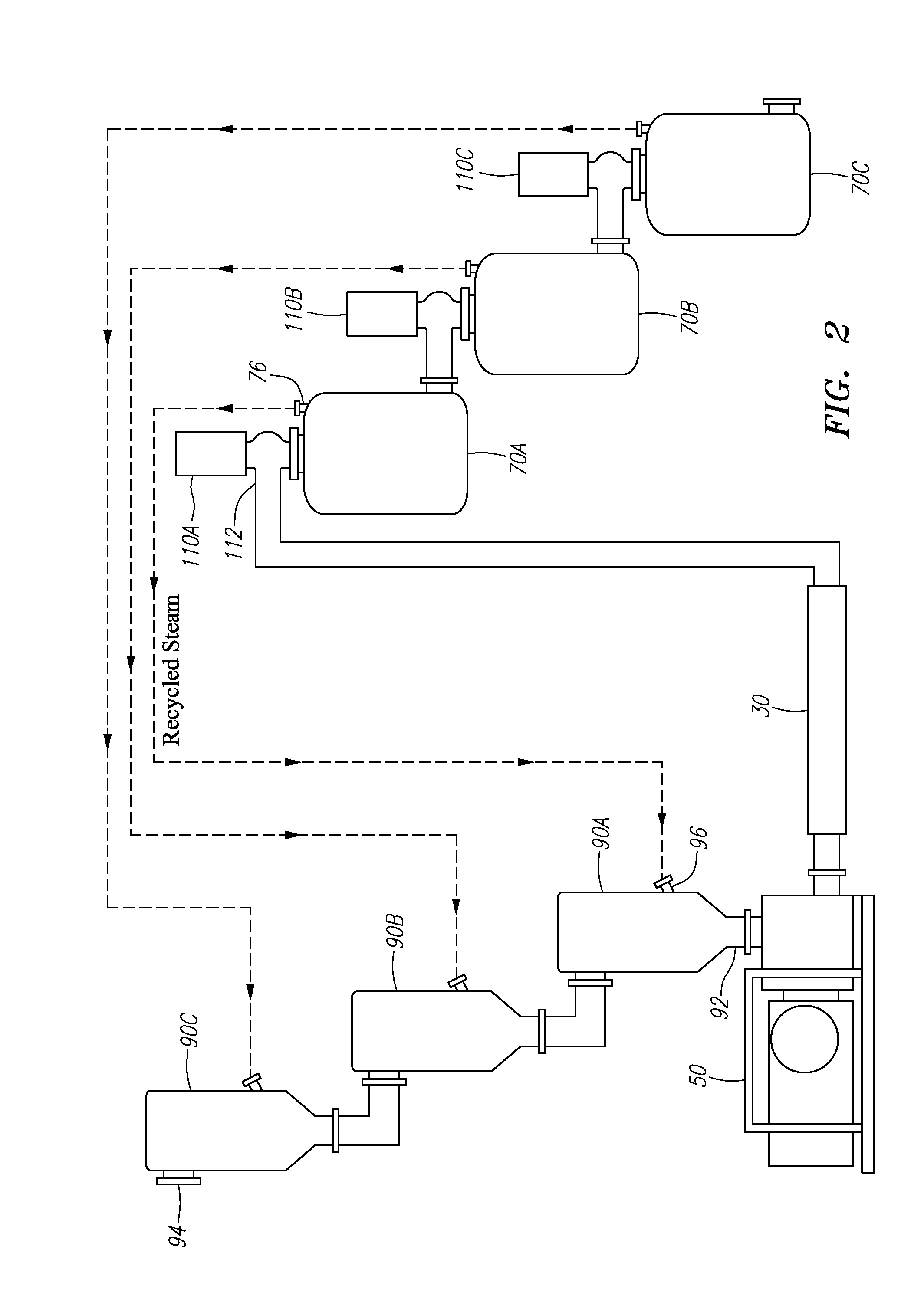
[0035] FIG. 2 illustrates a view of the heat recovery system of a continuous biomass treatment system with a plurality of flash vessels and a plurality of counter current splash vessels;
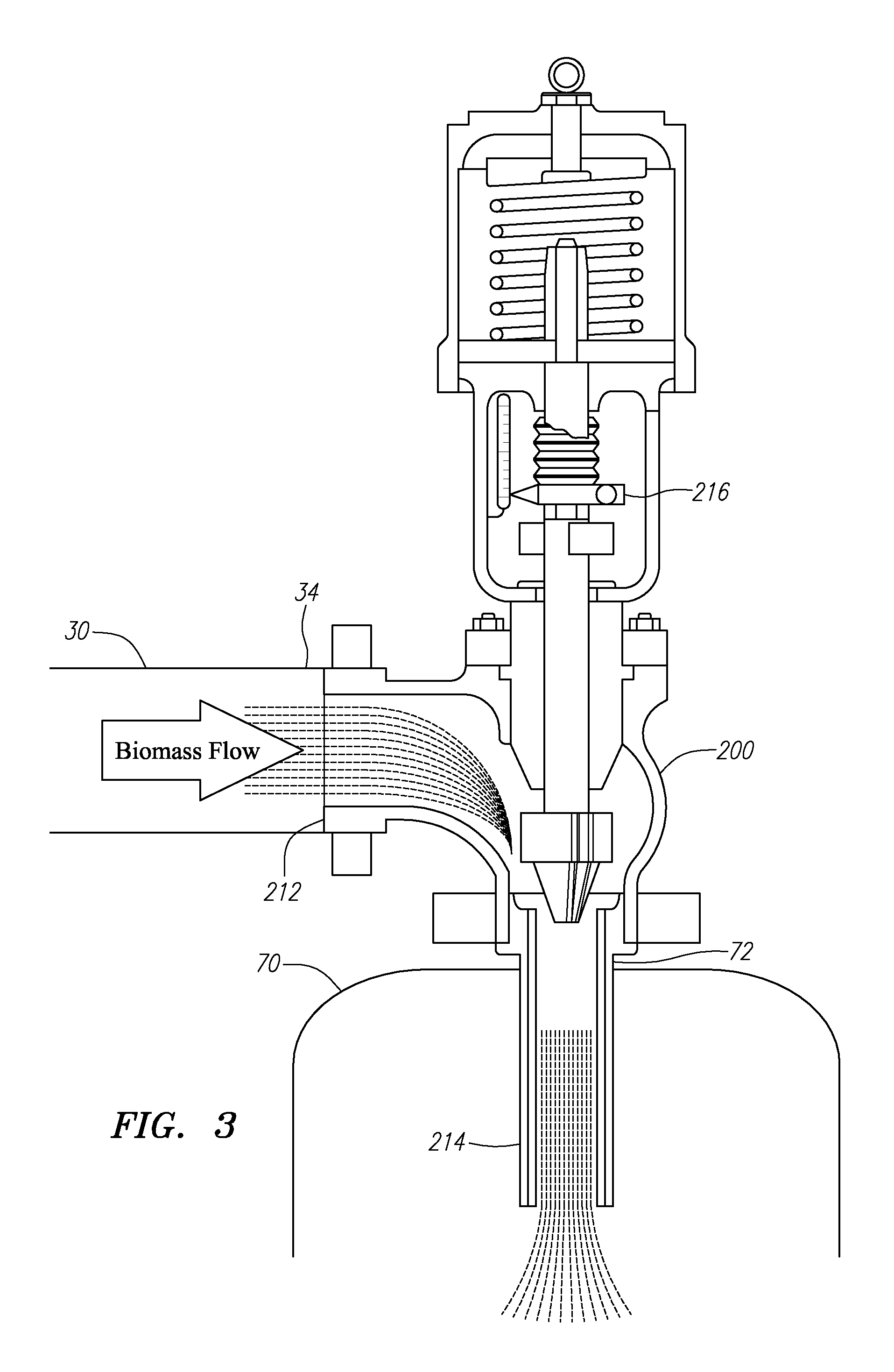
[0036] FIG. 3 illustrates a cross sectional view of a choke valve;
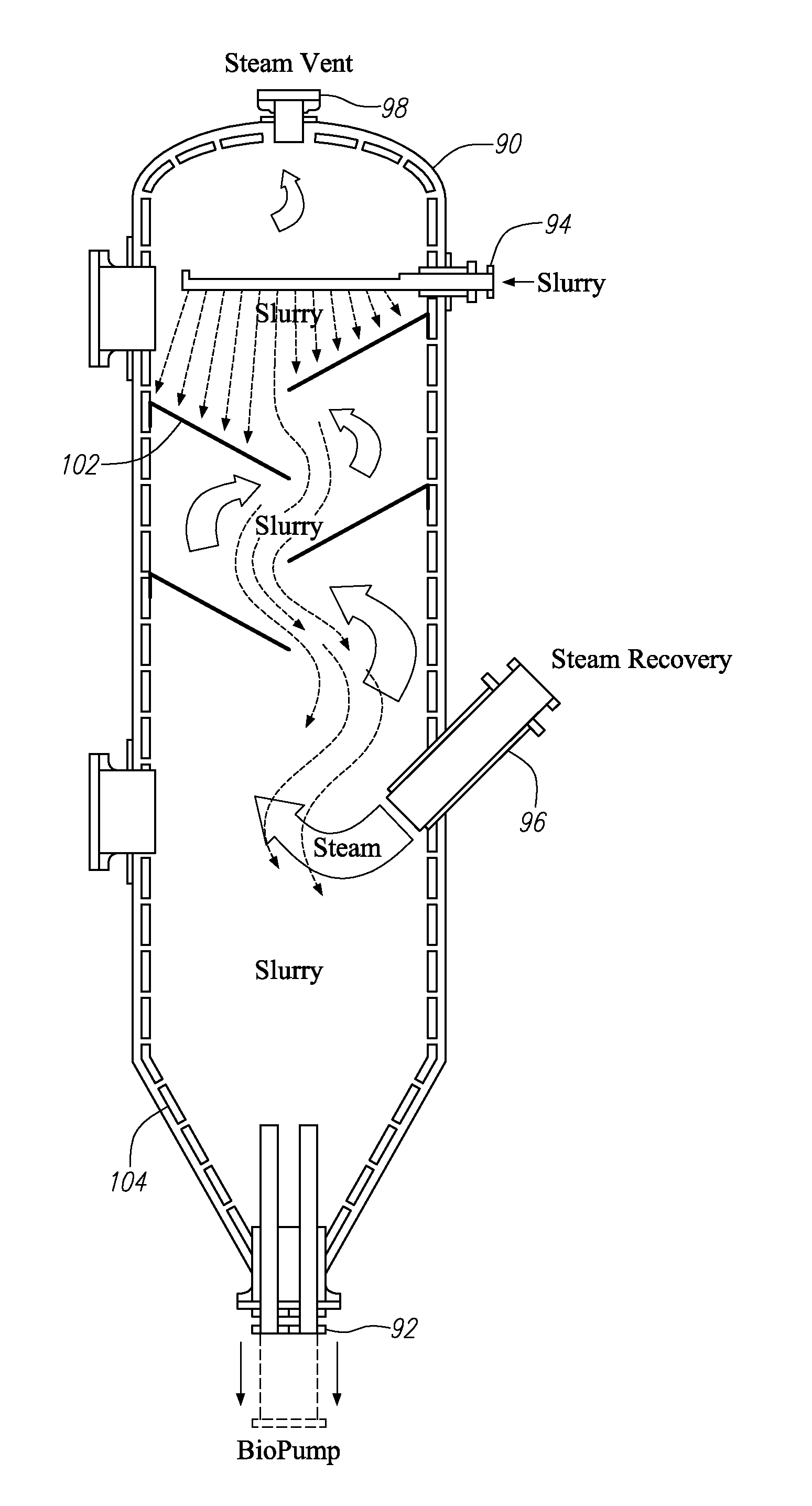
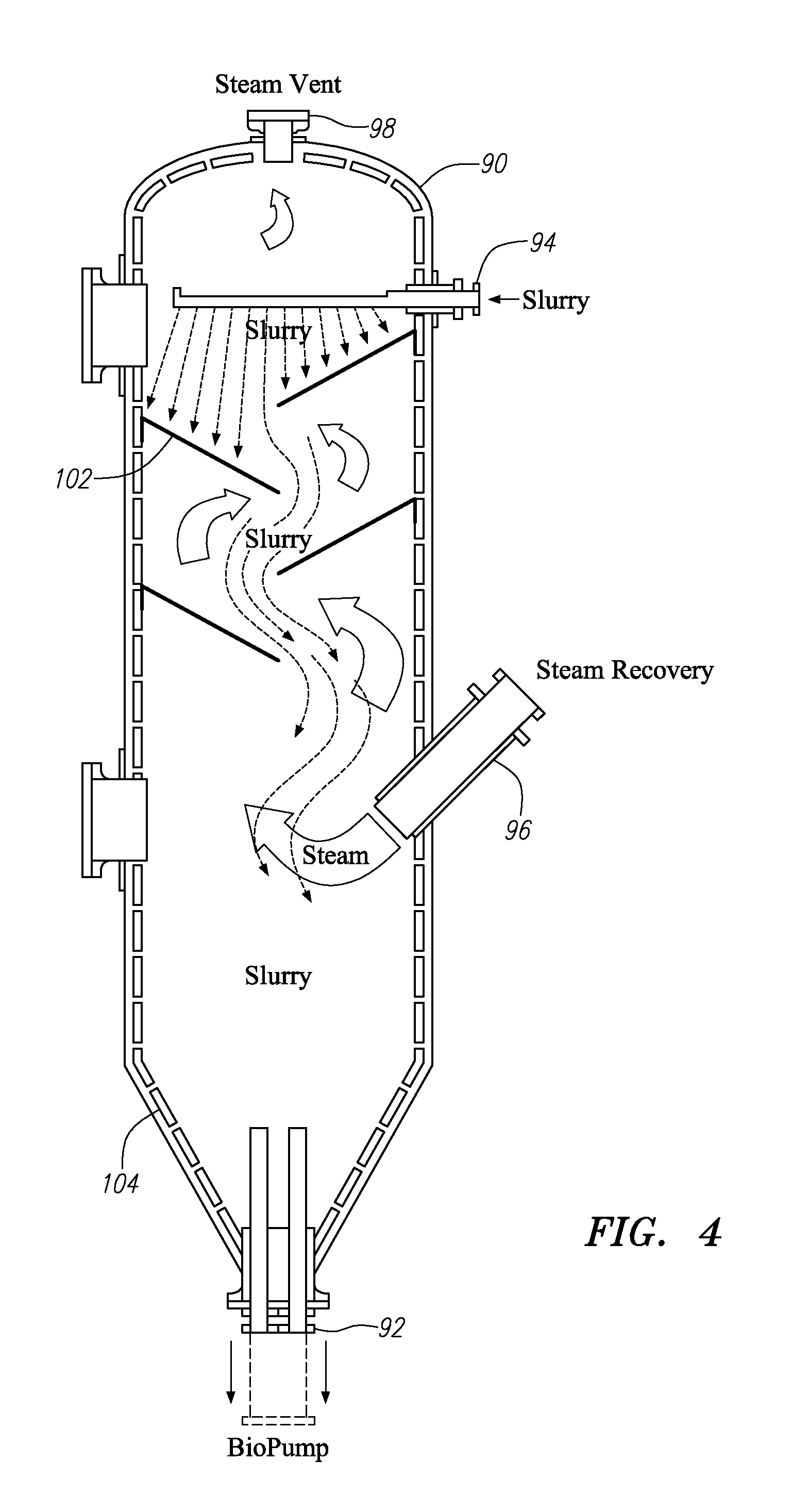
[0037] FIG. 4 illustrates a cross sectional view of an embodiment of a counter current splash vessel;
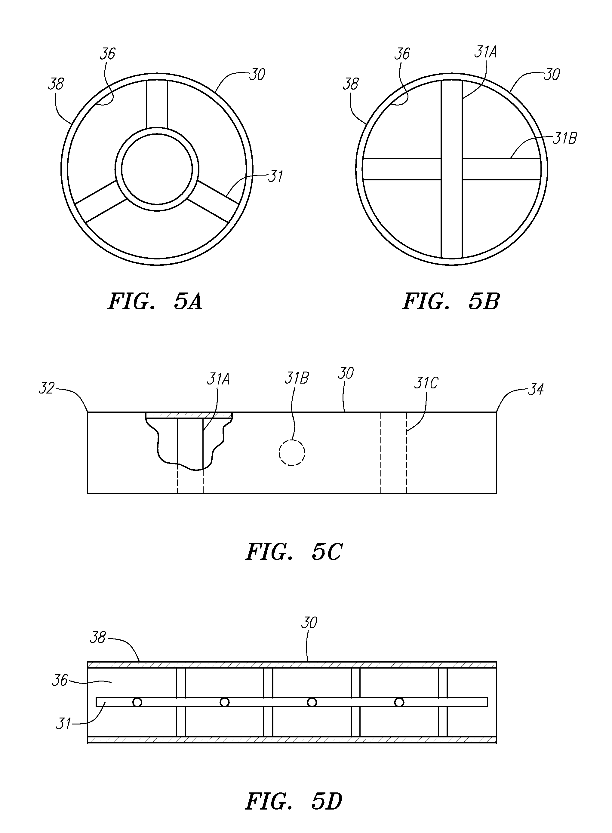
[0038] FIG. 5A illustrates a view down the axis of an embodiment of a pipe reactor containing a static mixer;
[0039] FIG. 5B illustrates a view down the axis of an embodiment of a pipe reactor containing an alternative form of a static mixer;
[0040] FIG. 5C illustrates an exterior view of an embodiment of a pipe reactor containing a static mixer;
[0041] FIG. 5D illustrates a cross sectional view of an embodiment of a pipe reactor with a static mixer slideably inserted in the interior of the pipe reactor;
[0042] FIG. 6 illustrates a schematic of a continuous biomass treatment method; and
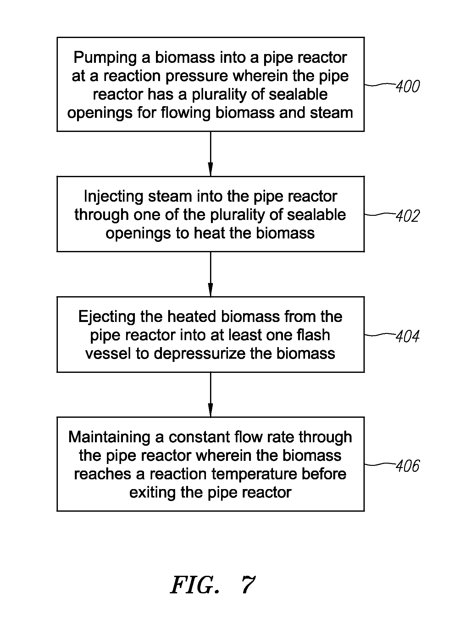
[0043] FIG. 7 illustrates a schematic of a continuous biomass treatment method.
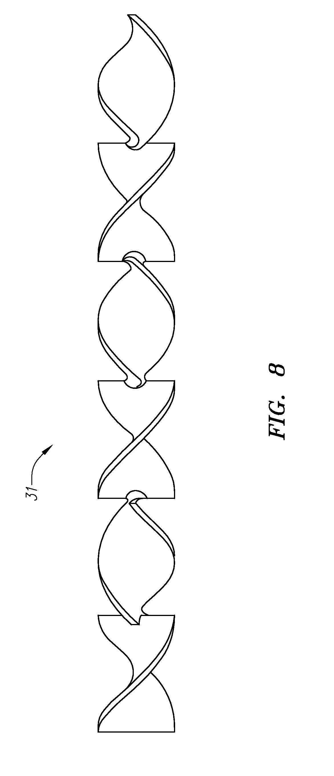
[0044] FIG. 8 illustrates a helical static mixer.
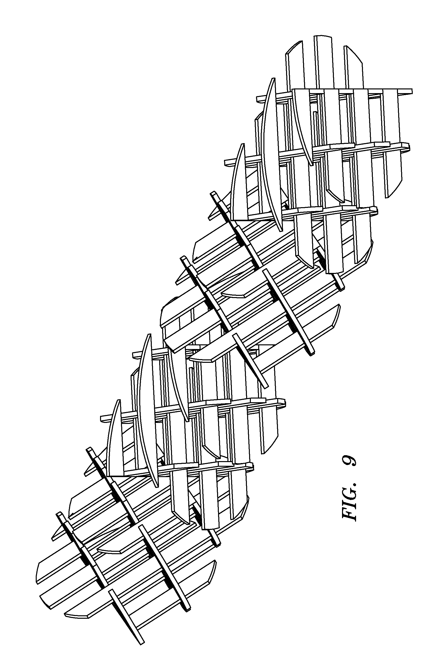
[0045] FIG. 9 illustrates a grid-type static mixer.
DETAILED DESCRIPTION OF THE PREFERRED EMBODIMENTS
[0046] In the following descriptions of the preferred embodiments, reference is made to the accompanying drawings that form a part hereof, and in which is shown by way of illustration specific embodiments in which the invention may be practiced. It is to be understood, however, that other embodiments may be utilized and structural changes may be made without departing from the scope of the present invention.
[0047] Consistent with its ordinary meaning as a renewable energy source, the term "biomass" is used herein to refer to living and recently dead biological material including carbohydrates, proteins and/or lipids that can be converted to fuel for industrial production. The biomass that may benefit from pretreatment in the systems and methods described herein comprise lignocellulosic biomass, which may include by way of non-limiting example, dead trees and branches, yard clippings, wood chips, agricultural residues (e.g., bagasse, rice straw, wheat straw, corn stover, etc.), straw, and energy crops (e.g., switch grass, hybrid poplar, willow, etc.).
[0048] As used herein, the term "pipe reactor" and "tubular reactor" are interchangeable and refer to a section of pipe in a system where chemical or other processes take place. For the purposes of the present invention, a "pipe reactor" and "tubular reactor" are devoid of any rotating parts that require connection from the interior to the exterior of the reaction chamber. This includes motor driven rotating augers used for stirring and any other means requiring a seal which allows rotation but prevents pressure leaks.
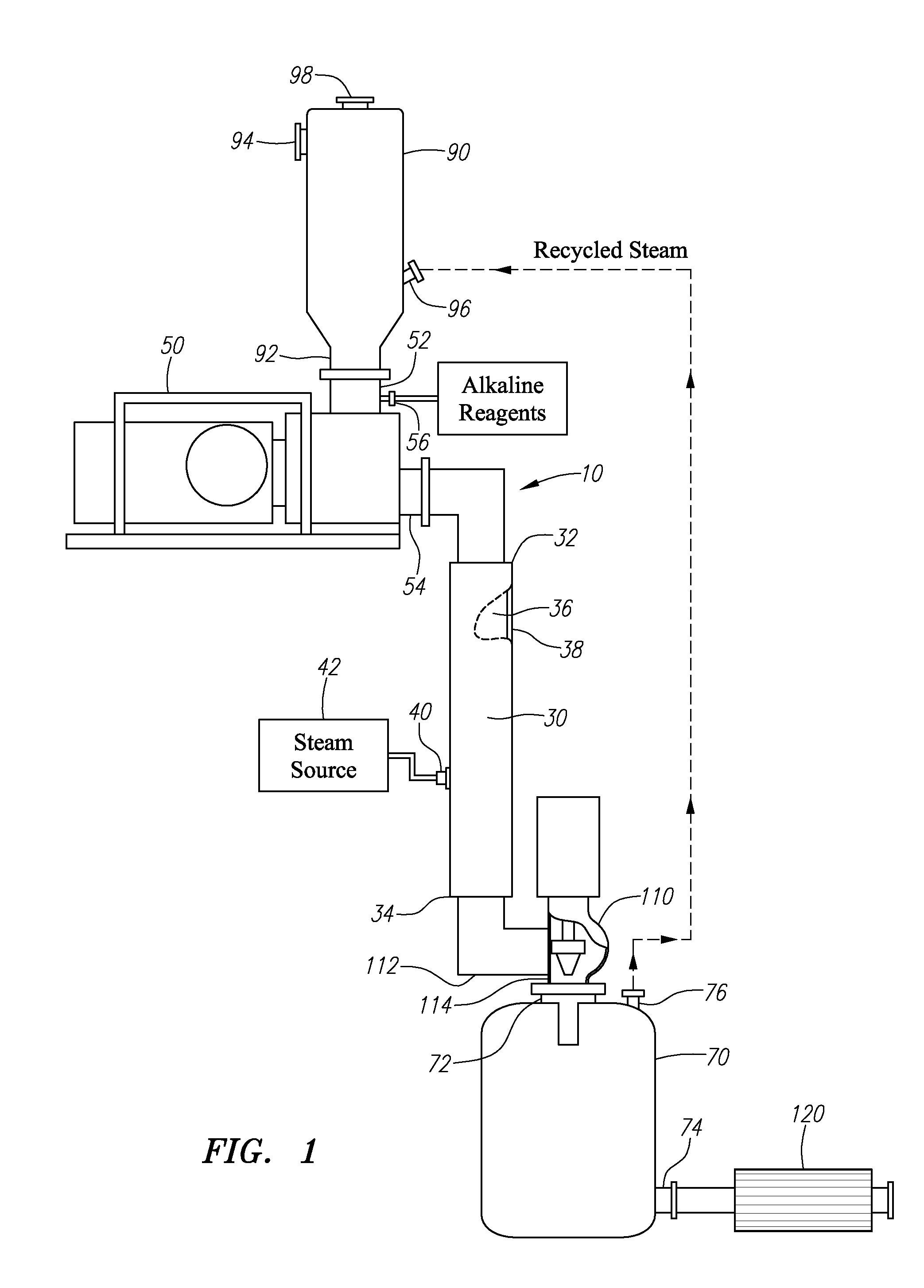
[0049] FIG. 1 illustrates a view of a continuous biomass treatment system 10. Treatment system 10 of the illustrated embodiment comprises counter current splash vessel 90, pump 50, pipe reactor 30, valve 110, flash vessel 70, and heat exchanger 120. While a counter current splash vessel 90 and heat exchanger 120 are shown in the FIG. 1 embodiment, other embodiments of treatment system 10 may be constructed in which a counter current splash vessel 90 and heat exchanger 120 are omitted.
[0050] In use, treatment system 10 is preferably designed to continuously flow biomass through the pipe reactor 30. The flow of the biomass may be controlled by the combination of the pump 50 and the valve 110. In the embodiment shown in FIG. 1, the biomass enters the counter current splash vessel 90 and is then pumped into the pipe reactor 30 by the pump 50. The valve 110 controls the flow of the biomass out of the pipe reactor 30 and into the flash vessel 70. The biomass exits the flash vessel 70 and proceeds through a heat exchanger 120.
[0051] The system 10 is designed to reduce the recalcitrance of lignocellulosic biomass to enzymatic saccharification and fermentation, and thereby render the biomass a more efficient feedstock for producing fossil fuel alternatives. Unlike other apparatus and systems used for the pretreatment of biomass that are complex and not designed for scaling, the present embodiment of treatment system 10 incorporates basic elements that may be easily and cost effectively scaled for large industrial production. Indeed, the system and methods described herein may be readily scaled to handle hundreds of tonnes per hour of lignocellulosic biomass.
[0052] As shown in FIG. 1, the biomass preferably enters treatment system 10 in the counter current splash vessel where it may be preconditioned with steam, heat or other additives. The biomass is then pumped into the pipe reactor 30 with a large industrial pump 50 capable of handling high pressures, temperatures, and solids. Once steady state is achieved within treatment system 10, when the biomass leaves the pump 50 and enters the pipe reactor, the biomass is already at the desired reaction pressure. The flow rate of the biomass may be controlled to ensure the biomass reaches a reaction temperature in the pipe reactor 30. The reaction pressure and reaction temperature are preferably set to reduce sufficiently the recalcitrance of the biomass to saccharification and/or fermentation when it rapidly depressurizes into the flash vessel 70. The valve 110 controls the flow of the biomass into the flash vessel 70. If desired, the biomass may be cooled by passing it through a heat exchanger 120.
[0053] Depending on the biomass that is being used with treatment system 10, it may be preferable to precondition the biomass before it enters the pipe reactor 30. In such a case it may be preferable to first have the biomass pass through a counter current splash vessel 90 as shown in FIG. 1.
[0054] In one embodiment, counter current splash vessel 90 with a biomass output 92 and a biomass input 94 is provided in communication with the input side 52 of the pump 50. The biomass may be preconditioned in the counter current splash vessel 90 in any way desirable prior to entering the pump 50. For example, the biomass may be heated or pressurized prior to entering the pump 50. In addition, water or steam could be added to the biomass to hydrate it. Furthermore, other additives, such as reagents or enzymes, could be added to the biomass prior to the biomass entering the pump 50. Such reagents or enzymes may be injected, for example, through an injection port 56. While the counter current splash vessel is one place where the biomass may be preconditioned, the biomass may be preconditioned by any number of methods prior to entering the pump 50. In addition, heat, steam, or additives can be added anywhere along the biomass path through the treatment system 10. Alternatively, instead of adding steam into the system 10 to heat the biomass, the biomass within system 10 may be heated using, for example, a steam jacket or other suitable means, to avoid dilution to the biomass.
[0055] In order to add steam to the biomass in the counter current splash vessel 90, the counter current splash vessel 90 may have a steam input 96. The steam input 96 injects steam near the bottom of the counter current splash vessel 90 so the steam will flow upwards. The upward flowing steam is used to pre-heat the biomass flowing downward from the biomass input 94 before it enters the pump 50.
[0056] Preferably, a counter current splash vessel 90 further comprises a steam vent 98 to vent the steam injected through steam input 96. The steam vent 98 prevents pressure from building up in the counter current splash vessel 90 and thereby allows steam to be continuously injected into the counter current splash vessel 90. In addition, steam vent 98 is preferably located proximately near the top of the counter current splash vessel 90 to enable the upward, counter current flow of steam from the bottom to the top of the vessel.
[0057] In a preferred embodiment, the steam that is injected into the counter current splash vessel 90 may be recycled from the flash vessel 70. When the biomass enters the flash vessel 70 a rapid depressurization of the biomass occurs. Heated steam is a by-product of the rapid depressurization. In order to make the treatment system 10 more efficient, one embodiment of the flash vessel 70 may have a steam output 76 to allow the steam that is a by-product of the rapid depressurization to be recycled. The recycled steam may be transferred from the steam output 76 of the flash vessel 70 and injected into the steam input 96 of the counter current splash vessel 90.
[0058] As shown in FIG. 1, a single counter current splash vessel 90 is depicted. While only a single counter current splash vessel 90 is shown, any number of counter current splash vessels can be used. For example, more than one counter current splash vessel may be used in series. In such an embodiment, the biomass output 92 of each counter current splash vessel 90 may be in communication with the biomass input 94 of the next counter current splash vessel 90. The biomass output 92 of the final counter current splash vessel 90 in the series is connected to the input side 52 of the pump 50. FIG. 2 illustrates one possible embodiment with multiple counter current splash vessels 90.
[0059] The advantages of having additional counter current splash vessels 90 includes allowing staged pre-heating of the biomass before it enters the pump 50. For example, when more than one counter current splash vessel 90 is used, it may also be preferable to use more than one flash vessel 70 in conjunction. The more stages over which the pressure within the pipe reactor 30 is released to atmosphere, the less severe the let down and the less wear that will occur on the interior of each of the flash vessels 70. The steam from each of the flash vessels 70 in series may be recycled by connecting their respective steam output 76 with the steam input 96 of one of the counter current splash vessels 90 in a counter current manner as shown in FIG. 2. The treatment system 10 shown in FIG. 2 also permits the temperature of the biomass to be increased in stages corresponding to each splash vessel 90, or three stages in the illustrated embodiment. As a result, a more controlled pre-heat may be performed to minimize likelihood that the biomass will be over heated or that the hemicellulose contained therein will be turned to inhibitory furfurals.
[0060] The counter current splash vessel 90, or series of vessels 90 or other biomass input reservoir, should be arranged to provide a continuous supply of biomass ready to be pumped into the pipe reactor 30. In order to pump the biomass into the pipe reactor 30 the treatment system preferably has a pump 50 with input side 52 and an output side 54.
[0061] A high solids content biomass slurry enters the input side 52 of the pump 50 and is pumped out of the output side 54 of the pump 50 preferably at a reaction pressure. The output side 54 of the pump 50 is in communication with the input end 32 of the pipe reactor 30. The biomass is pumped from the input side 52 of the pump 50, through the pump and into the input end 32 of the pipe reactor 30.
[0062] The pump 50 is preferably designed to handle slurries with high solids content, such as pastes or sludge, at high pressures, and high temperatures. Preferably, pump 50 is capable of pumping slurries with 50 to 90% solids by mass, more preferably 60 to 80% by mass, at pressures in the range of about 350 to 450 pounds per square inch, and at temperatures in the range of about 120 to 220.degree. C.
[0063] Using a pump 50 with the foregoing characteristics allows the pump 50 to elevate the biomass to the desired reaction pressure on the output side 54 of the pump 50. By incorporating a pump 50 that can elevate the biomass to the reaction pressure, batch processing may be eliminated and the pump 50 may continuously feed the biomass into the pipe reactor 30. Continuous processing is advantageous because it saves time and is therefore more economically viable for large scale, low cost processing of biomass. In addition, continuous processing avoids pressure swings as described previously.
[0064] The pump 50 is preferably a positive displacement pump; however, the pump 50 may be any type of pump that can pump a slurry of biomass with high solids content under high pressure and high temperature. For example, the pump 50 may be a piston pump, a piston diaphragm pump, a positive displacement rotary pump including internal or external gears, or a screw pump. Preferably pump 50 is a GEHO.RTM. pump by Weir Minerals, 2701 South Stoughton Road Madison, Wis. 53716. Alternatively, pump 50 is preferably a pump manufactured by Moyno, Inc 1895 W. Jefferson Springfield, Ohio 45506 suitable for slurries with high solids, such as the MOYNO.RTM. 2000 HS System pump.
[0065] In operation, the pump 50 may serve to help control the flow rate of biomass through the pipe reactor 30. By continuously pumping biomass into the input end 32 of the pipe reactor 30, biomass will be forced through the pipe reactor 30. The pump 50 may increase the flow of biomass through the pipe reactor 30 by pumping more biomass into the pipe reactor 30 and thereby increasing the pressure in the pipe reactor 30.
[0066] Once the biomass leaves the pump 50, preferably at the reaction pressure, the biomass must be raised to the desired reaction temperature. The treatment system 10 elevates the biomass to the reaction temperature by passing the biomass through pipe reactor 30.
[0067] A pipe reactor is employed to raise the temperature of the biomass to its reaction temperature because such reactors may be easily and economically scaled. Existing reactor designs for pretreating lignocellulosic biomass in advance of the saccharification and fermentation steps of the conversion process are complicated and incorporate rotating parts such as stirring augers. The use of a pipe reactor 30 allows the treatment system 10 to employ a simple and straightforward design that is easy to scale because, in part, it does not incorporate a complex seal. These advantages allow a pipe reactor of substantial size to be constructed with less capital than a more complex reactor design. Furthermore, the safety concerns and down times associated with maintenance of complicated pressure seals is eliminated when using a pipe reactor.
[0068] While pipe reactor 30 is preferably a cylindrical pipe, pipe reactor 30 may be any shape tube, conduit, or hollow body capable of biomass transfer. Cylindrical pipe is preferable because a majority of pipe is manufactured in a cylindrical shape and therefore, cylindrical pipe is often cheap and readily available.
[0069] The pipe reactor 30 has an interior 36 and an exterior 38. As the biomass passes through the interior of the pipe reactor 30, processing heat may be added to raise the biomass to the desired reaction temperature. Additional process heat may be added to the biomass through a number of methods, including heating the exterior of the pipe reactor 30, injecting steam from a steam source 42 into the interior of pipe reactor 30 through a steam injection port, such as steam injection port 40, or by any other suitable method of adding energy. In the embodiment shown in FIG. 1, pipe reactor 30 contains a single steam injection port 40. However, a plurality of steam inputs may be used.
[0070] Once the biomass reaches the reaction temperature it may be preferable to hold the biomass at that temperature for a period of time. Because the biomass is continuously moving through the pipe reactor 30, the volume of the pipe reactor 30 will need to be big enough to accommodate the desired dwell time of the biomass at the reaction temperature. The pipe length and diameter may be used as design variables given a desired flow rate, reaction time, and reaction temperature.
[0071] The pipe reactor 30 may be any length. However, preferably the length of the pipe reactor is determined using the desired retention time of the biomass in the pipe reactor 30. The desired retention time can be divided by the constant flow rate of the biomass through the pipe reactor 30 to estimate the preferable pipe length. The retention time of the biomass in the pipe reactor 30 is preferably short, in the range of about 1 to 30 minutes, and more preferably in a range of between about 5 and 30 minutes. Preferably, the retention time of the biomass in pipe reactor 30 is as low as possible to achieve the desired pretreatment, but the retention time should be at least sufficient to cause the biomass to reach a desired reaction temperature. Reaction temperatures are preferably between about 120-220 degrees Celsius. Short retention times are preferred not only because they increase throughput and improve the overall efficiency of the pretreatment process. However, shorter retention times will also minimize the amount of undesirable, and potentially inhibitory, side products, such as furfurals, that are formed within the biomass.
[0072] Preheating the biomass in splash vessel 90 will also reduce the necessary retention time in pipe reactor 30 and the amount of energy required to be input into the pipe reactor 30.
[0073] Although as shown in FIG. 1, pipe reactor 30 is shown disposed in a vertical orientation, and preferably in final form the pipe reactor may be vertical, the pipe reactor can be in any orientation or conceivable angle including horizontal. The vertical orientation may be preferable because it allows for gravity to assist in the flow of the biomass through the pipe reactor 30.
[0074] As the biomass leaves the pipe reactor at high pressure, it enters a low pressure flash vessel 70. In order to control the flow of the biomass from the pipe reactor 30 into the flash vessel 70, and to separate the pressure regions, a valve 110 is incorporated in the treatment system 10. The pipe reactor 30 has an output end 34 that is in communication with a valve 110 at the valve input 112. The valve 110 is preferably a choke valve, but other valves that are suitable for handling slurries with high solids content (such as a paste or sludge) at high temperatures and that may also handle high pressure drops may also be used.
[0075] In operation, the valve 110, along with the pump 50, is used to control the flow rate of the biomass through the pipe reactor 30. Preferably, the valve 110 is adjustable to control the rate of biomass flow through the pipe reactor 30 and into the flash vessel 70 and to control the pressure in the pipe reactor 30. A choke valve is preferably used because such valves can control the flow rate of the biomass more linearly while maintaining the pressure difference across the valve interface. In addition, choke valves are less dependant on changes in fluid viscosity. These advantages allow the choke valve to better control the flow of the biomass through the pipe reactor 30.
[0076] As noted, choke valves are preferable because they are designed to maintain a pressure drop across the valve interface. The valve 110 is the interface between the higher pressure upstream flow, as the biomass leaves the pipe reactor 30, and the lower pressure down stream flow, as the biomass enters the flash vessel 70. Therefore, it is preferable to use a choke valve because it can maintain the pressure difference across the valve interface.
[0077] In addition to a more linear flow and the ability to maintain a pressure differential, choke valves are preferable because they are less susceptible to damage than other valve designs when limiting flow. For example, as a ball valve begins to close, the area of the pipe is effectively narrowed and because of the Bernoulli principle, the biomass will begin to flow faster through the valve. As the high solids content slurry of biomass rushes through the opening in the ball valve at a higher velocity, the edges of the valve may be damaged, eventually ruining the ball valve. Because of the design of the choke valve, it is not as susceptible to the same type of damage during valve adjustment.
[0078] As the biomass flows out of the valve 110 through the valve output 114 the biomass enters the flash vessel 70. The flash vessel 70 has an input 72 that is in communication with the valve output 114. As the biomass leaves the pipe reactor 30 and enters the flash vessel 70 through the valve 110, a pressure drop occurs. When the biomass has been maintained at the necessary reaction pressure and reaction temperature for the required period in the pipe reactor 30, the structure of the organic polymer fibers in the biomass is susceptible to being expanded or exploded as a result of the rapid pressure drop. The rapid pressure drop thus causes the steam trapped in the biomass to rapidly expand and disrupt the polymer network of cellulose, hemicellulose, and lignin forming the biomass structure, thereby reducing the recalcitrance of the biomass to enzymatic saccharification of the cellulose and/or hemicellulose, contained therein. In some implementations, it may be desirable to carry out the process at a sufficiently high temperature to cause the hydrolysis of at least some, if not all, of the hemicellulose contained in the biomass feedstock. By contrast, in other embodiments, it may desirable to use a reaction temperature, pressure, and retention time that ensures the majority of the hemicellulose, if not all of the hemicellulose, will be retained in the pretreated biomass following discharge from pipe reactor 30.
[0079] In one embodiment, the flash vessel 70 may comprise a pressure let down cyclone. The flash vessel 70 may also be equipped with an auger to facilitate removal of the pretreated biomass from the bottom of the flash vessel. If a pressure let down cyclone is used as the flash vessel 70, it may similarly be equipped with an auger to facilitate material removal.
[0080] According to a further embodiment, the treatment system 10 may further comprise a second pump 50, pipe reactor 30, valve 110, and flash vessel 110 in series with the first pump 50, pipe reactor 30, valve 110, and flash vessel 110 to form a two-stage system. This arrangement may be used to permit the removal of hemicellulose from the lignocellulosic biomass between the first and second stages. Further, the first stage of the process may be carried out at generally lower temperatures and longer dwell times, to limit the formation of side products such as furfurals.
[0081] As shown in FIG. 1 a single valve 110 and a single flash vessel 70 are depicted. If only a single valve 110 and a single flash vessel are used, the pressure drop between the pipe reactor 30 and the flash vessel 70 may be quite severe. For example, if only a single flash vessel is used, the biomass may be going from the reaction pressure within the pipe reactor 30, back to atmospheric pressure all at once. If the pressure drop is too severe, the expanding biomass may damage the interior of the flash vessel 70. Therefore, in certain embodiments, it may be desirable to use a plurality of pressure let down stages disposed in series, wherein each pressure let down stage comprises a valve 110 and flash vessel 70 so that each valve 110 and flash vessel 70 of a let down stage is disposed in series with a valve 110 and flash vessel 70 of another let down stage. In this manner, the pressure drop between each let down stage may be controlled to a desired level while still exposing the biomass to a sufficient pressure drop across each valve 110 to sufficiently alter the structure (and possibly the composition) of the biomass and thereby reduce its recalcitrance.
[0082] In an embodiment with multiple pressure let down stages, the input 112 of each additional valve 110 used in the treatment system 10 may be in communication with the output opening 74 of the flash vessel 70 of the previous let down stage. Further, the input opening 72 of each additional flash vessel 70 may be connected to the output 114 of the valve 110 in its let down stage. In this way, any desired number of valves 110 and flash vessels 70 may be used in series. In the embodiment shown in FIG. 2, three let down stages in series are employed.
[0083] The more valves 110 and flash vessels 70 that are used, the less severe the pressure drop becomes into any individual flash vessel 70. However, if the pressure drop is not large enough the crystalline structure of the biomass may not be sufficiently disorganized to allow efficient post processing of the biomass into fossil fuel alternatives. In other words, the recalcitrance of the biomass to saccharification of the cellulose and/or hemicellulose contained therein may not be sufficiently reduced.
[0084] As mentioned above with respect to the counter current splash vessel 90, additives may be injected into the biomass to increase the effectiveness of the treatment system 10 on the biomass. In one embodiment of the invention, the pump 50 may further comprise a port 56 to allow reagents to be injected into the biomass on the suction side of the pump 50. The reagents may be any substance that enhances the reaction, including alkalines, acids, buffers or solvents. Alkaline reagents may be used, for example, to prevent acids from forming during the treatment process or to solubulize the lignin in the biomass. In general, any alkaline reagent that reduces the pH but does not adversely react with the biomass may be used. By way of non-limiting example, specific reagents that may be used advantageously in the treatment system 10 include sodium hydroxide, sodium sulphite, lime, ethanol, sulfur dioxide, and carbon dioxide.
[0085] After the biomass has passed through the pipe reactor 30 and into the flash vessel 70, the biomass is at an elevated temperature. Therefore, it may be preferable to cool the biomass after it leaves the flash vessel 70. In one embodiment, the treatment system 10 may further comprise a heat exchanger 120. The heat exchanger 120 is in communication with the biomass output 74 of the flash vessel 70. The heat exchanger may be of a shell or tube type design but may also be any type of heat exchanger that allows for proper cooling of the biomass.
[0086] FIG. 2 illustrates a counter current heat recovery system for a continuous biomass treatment system 10 comprising a plurality of flash vessels 70 and a plurality of counter current splash vessels 90. In particular, as shown in FIG. 2, counter current splash vessel 90C may be connected in series with a second counter current splash vessel 90B which may be connected in series with a third counter current splash vessel 90A. The biomass enters counter current splash vessel 90C at a biomass input 94. The biomass flows through counter current splash vessel 90C and into counter current splash vessel 90B and continues into counter current splash vessel 90A where it eventually leaves through a biomass output 92 and into the pump 50.
[0087] The use of more than one counter current splash vessel 90 as shown in FIG. 2 allows for staged pre-heating with the temperature in each stage increasing. This is advantageous, as it potentially allows the dwell time of the biomass at higher temperatures to be reduced, thereby potentially limiting undesirable side products from being formed. Using a plurality of splash vessels 90 in series will also permit the staged increase in the pressure of the biomass in the treatment system 10 before it enters the pump 50. For example, a two-stage pump (not shown) may be used between the splash vessels to generate a pressure differential between counter current splash vessel 90C and counter current splash vessel 90B. The two stage pump may be used to maintain the pressure difference and keep the flow of biomass moving. Similarly, if a pressure difference is desired between counter current splash vessel 90B and counter current splash vessel 90A, a two-stage pump (not shown) may be installed between them for the same reasons.
[0088] More than one pressure let down stage, wherein each let down stage comprises a valve 110 and flash vessel 70, may also be used in treatment system 10. In the embodiment shown in FIG. 2, the treatment system 10 includes three pressure let down stages. In particular, pipe reactor 30 is in communication with a first valve 110A of the first stage at an input 112, which is in turn connected in series to a first flash vessel 70A in the first stage. Flash vessel 70A is connected to a second valve 110B in the second pressure let down stage, which is in turn in communication with a second flash vessel 70B in the second stage. Flash vessel 70B is then in communication with a third valve 110C in the third let down stage, which is in communication with a third flash vessel 70C in the third stage. The biomass leaves the pipe reactor 30 and flows through the first valve 110A and into the first flash vessel 70A. The biomass continues on through the second valve 110B and into the second flash vessel 70B. The biomass continues further through the third valve 110C and into the third flash vessel 70C.
[0089] While three counter current splash vessels 90, three valves 110, and three flash vessels 70 are shown in series in FIG. 2, and preferably two to three may be used, any number of counter current splash vessels 90, valves 110, and flash vessels 70 may be used.
[0090] It is advantageous, but not required, to match the number of flash vessels 70 with the number of counter current splash vessels 90 for the purposes of steam recovery. As shown in FIG. 2, steam may be recovered from flash vessel 70A through a steam output 76 and injected to pre-heat the biomass in the counter current splash vessel 90A. Similarly, steam may be recovered from flash vessel 70B to pre-heat the biomass in counter current splash vessel 90B and steam may be recovered from flash vessel 70C to pre-heat the biomass in counter current splash vessel 90C.
[0091] Steam recovered from the first flash vessel 70A, after the pipe reactor 30, should preferably be used to pre-heat the biomass in the first counter current splash vessel 90A, before the pipe reactor 30. This is preferred because the pressure and temperature is preferably increasing with each counter current splash vessel in series as the biomass approaches the pipe reactor and the pressure and temperature is decreasing with each flash vessel in series as the biomass leaves the pipe reactor 30. By matching the steam recovery of the flash vessels 70 in series, as they proceed downstream from the pipe reactor 30, with the counter current splash vessels 90, as they proceed upstream away from the pipe reactor 30, the pressures of the connected vessels may be more closely matched.
[0092] FIG. 3 illustrates a cross sectional view of a choke valve of the present invention. As shown in FIG. 3, choke valve 200 may comprise an input 212, an output 214 and a means to control the rate of flow of the biomass 216. When used as an element of treatment system 10, the choke valve input 212 may be in communication with the pipe reactor 30 at the output end 34. The choke valve output 214 may be in communication with the flash vessel 70 input opening 72.
[0093] In operation, the high pressure, high solids content biomass slurry enters the choke valve 200 through the input 212 and exits to a lower pressure flash vessel 70. The choke valve 200 may have a biomass flow control means 216 to control the flow rate of the biomass through the choke valve 200. This allows the choke valve 200 to regulate pressure and flow rate in the upstream pipe reactor 30.
[0094] FIG. 4 illustrates a cross sectional view of an embodiment of a counter current splash vessel. As shown in FIG. 4, counter current splash vessel 90 may comprise a biomass input 94 and a biomass output 92. Counter current splash vessel 90 may further comprise a steam input 96, a steam vent 98, and baffles 102. In one embodiment of a counter current splash vessel 90, heat in the form of steam may flow in the opposite direction from the flow of the biomass being heated. Biomass enters the counter current splash vessel 90 through a biomass input 94 and flows downward towards the biomass output 92. The steam is injected at the steam input 96 and flows up towards the steam vent 98, in the opposite direction of the downward flowing biomass.
[0095] In one embodiment, as shown in FIG. 4, baffles 102 may be disposed on the inside of the counter current splash vessel 90 to aid in the heat transfer process. Baffles increase the mixing of the downward flowing biomass by directing biomass through the path of the upwardly flowing steam. The use of baffles inside the counter current splash vessel 90 may increases the efficiency of the heat transfer between the steam and the biomass.
[0096] In order to better retain the heat within each counter current splash vessel 90 and therefore within the biomass, each counter current splash vessel 90 may be insulated with any suitable material. Further, in order to protect the interior walls of each splash vessel 90 from erosion due to the moving biomass and added reagents, if any, the walls of each splash vessel 90 are preferably lined with bricks to form a brick liner 104. Lining the walls of splash vessel 90 with brick liner 104 made from refractory bricks is also advantageous as it will permit each splash vessel 90 to be constructed out of mild steel as opposed to an expensive alloy material, which will lower the cost of the splash vessels considerably. The brick lining 104 will protect the mild steel construction and may be readily maintained using techniques known in the art. Likewise, the interior surfaces of the pipe reactor 30 and each flash vessel 70 are preferably lined with brick to form a brick liner 104, thereby allowing mild steel to be used as the construction material for these components of the treatment system 10 as well.
[0097] FIG. 5A illustrates a view down the axis of an embodiment of a pipe reactor containing a static mixer 31. The use of a static mixer 31 is preferable because the mixer can provide mixing without requiring complex seals between the interior 36 and exterior 38 of the pipe reactor 30. A static mixer 31 can be used in combination with the pipe reactor 30 to increase the efficiency of the heat transfer to the biomass as it passes through the pipe reactor 30. Mixing is accomplished by disturbing the flow of biomass in the radial direction so that the biomass material near the interior wall 36 of the pipe reactor 30 and the biomass material along the center axis of the pipe reactor 30 reach equilibrium.
[0098] As shown in FIG. 5A, the static mixer 31 is disposed on the interior 36 of the pipe reactor 30. Preferably the static mixer 31 may be welded to the in interior 36 of the pipe reactor 30; however, the static mixer 31 can be brazed, tacked, press fitted or affixed by any other manner that provides sufficient rigidity.
[0099] The static mixer 31 of the embodiment shown in FIG. 5A has a circular member at its center with protruding members spaced at 120 degrees. However, the static mixer 31 can have any shape suitable for facilitating the mixing of high solid content slurries. For example, the static mixer 31 can comprise a single mixing bar spanning the interior of pipe reactor 30 or it can comprise a more complex mixing element as shown in FIG. 5A or some of the other embodiments described below.
[0100] FIG. 5B illustrates a view down the axis of an embodiment of a pipe reactor 30 that includes an alternative embodiment of a static mixer 30. As shown in FIG. 5B, static mixer 31 comprises a plurality of mixer bars 31A and 31B. While FIG. 5B illustrates only two mixer bars, any number of mixer bars may be used.
[0101] FIG. 5C illustrates an exterior view of an embodiment of a pipe reactor 30 containing a static mixer 31 comprising mixer bars 31A, 31B, and 31C. As shown in FIG. 5C, mixing bars 31A, 31B, and 31C are radially rotated with respect to each other. In the present embodiment, each mixing bar is rotated by 90 degrees from the previous mixing bar in the pipe reactor 30. However, other angles may also be used.
[0102] The mixer bars 31A, 31B, and 31C of static mixer 31 may be fixed to the pipe reactor 30 in a variety of ways, including by extending through a hole in the pipe reactor 30 so that the mixing bars 31 may be affixed from the exterior 38 of the pipe reactor 30. An advantage to passing the bars through the pipe reactor 30 is that the bars may be welded or affixed in place from the outside of the pipe reactor.
[0103] FIG. 5D illustrates a cross sectional view of an embodiment of a pipe reactor with a static mixer 31 that is slidably inserted into the interior of the pipe reactor. Rather than being affixed to the walls of the pipe reactor, the static mixer 31 may just be contained within it. As shown in FIG. 5D, the static mixer 31 comprises a long bar that runs along the axis of the pipe reactor 30 with mixer bars extending out radially along the length of the static mixer 31. While a particular static mixer 31 shape is shown in FIG. 5D, the shape of the static mixer 31 can very greatly. For example, the static mixer 31 could have less or more radial mixer bars. The static mixer 31 could also have a more complex cross sectional design. For example, the static mixer 31 could have the cross-sectional design shown in FIG. 5A running along the length of the axis of pipe reactor 30. Alternatively, the static mixer 31 may comprise a helical static mixer such as illustrated in FIG. 8 or a grid-type static mixer 31 such as illustrated in FIG. 9. Other static mixers that are suitable for mixing high solids slurries may also be used.
[0104] FIG. 6 illustrates a schematic of a continuous biomass treatment method. In step 300, a biomass slurry is pumped with a pump into a pipe reactor at a reaction pressure, wherein the pipe reactor does not have a mixing component that passes from the interior to the exterior and rotates with respect to the pipe. In step 302, the biomass within the pipe reactor is heated to a desired reaction temperature, preferably by the injection of steam into the pipe reactor. In other embodiments, the biomass within the pipe reactor may be heated by another means, such as by a steam jacket. In step 304 the heated biomass is ejected from the pipe reactor through a valve into a flash vessel to rapidly depressurize the biomass. In step 306, a constant flow rate is maintained through the pipe reactor, wherein the biomass reaches the reaction temperature before exiting the pipe reactor. Preferably the biomass reaches the reaction temperature by continuously performing the pumping, heating, and ejecting steps.
[0105] FIG. 7 illustrates an alternative continuous biomass treatment method. In step 400, a biomass slurry is pumped into a pipe reactor at a reaction pressure wherein the pipe reactor has no motor driven stirring method and wherein the pipe reactor has a plurality of sealable openings for flowing biomass and steam. In step 402, the biomass is heated within the pipe reactor to a desired reaction temperature, preferably by injecting steam into the pipe reactor. In step 404, the heated biomass is ejected from the pipe reactor through a valve into at least one flash vessel to rapidly depressurize the biomass. In step 406, a constant flow is maintained through the pipe reactor, wherein the biomass reaches the reaction temperature before exiting the pipe reactor. Preferably the biomass reaches the reaction temperature by continuously performing the pumping, heating, and ejecting steps.
[0106] The foregoing description of the preferred embodiment of the invention has been presented for the purpose of illustration and description. It is not intended to be exhaustive or to limit the invention to the precise form disclosed. Many modifications and variations are possible in light of the above teachings. It is intended that the scope of the invention not be limited by this detailed description, but by the claims and the equivalents to the claims that are appended hereto.
* * * * *
D00000
D00001
D00002
D00003
D00004
D00005
D00006
D00007
D00008
D00009
XML
uspto.report is an independent third-party trademark research tool that is not affiliated, endorsed, or sponsored by the United States Patent and Trademark Office (USPTO) or any other governmental organization. The information provided by uspto.report is based on publicly available data at the time of writing and is intended for informational purposes only.
While we strive to provide accurate and up-to-date information, we do not guarantee the accuracy, completeness, reliability, or suitability of the information displayed on this site. The use of this site is at your own risk. Any reliance you place on such information is therefore strictly at your own risk.
All official trademark data, including owner information, should be verified by visiting the official USPTO website at www.uspto.gov. This site is not intended to replace professional legal advice and should not be used as a substitute for consulting with a legal professional who is knowledgeable about trademark law.