Transformable Structure For Producing A Multi Thread Single Line Stitch And Method And Machine For Its Realization
Mingazhev; Askar Dzhamilevich ; et al.
U.S. patent application number 12/491475 was filed with the patent office on 2010-12-30 for transformable structure for producing a multi thread single line stitch and method and machine for its realization. Invention is credited to Askar Dzhamilevich Mingazhev, Bruce Alan Pelkey.
| Application Number | 20100326341 12/491475 |
| Document ID | / |
| Family ID | 43379338 |
| Filed Date | 2010-12-30 |


View All Diagrams
| United States Patent Application | 20100326341 |
| Kind Code | A1 |
| Mingazhev; Askar Dzhamilevich ; et al. | December 30, 2010 |
TRANSFORMABLE STRUCTURE FOR PRODUCING A MULTI THREAD SINGLE LINE STITCH AND METHOD AND MACHINE FOR ITS REALIZATION
Abstract
A multi-thread single-line chain stitch line, consisting of at least three threads. This method provides for the formation of variable structures of stitches, based on varying sequences for the conjoining of several top threads, loaded to their individual needles, with several bottom threads, loaded to their individual loopers. The method suggests intertwining top threads between each other. The proposed stitch structure provides homogeneity of mechanical stresses in the stitch line, resulting in higher strength and durability. The machine to provide such stitch line comprises a revolver, bringing required needles to the operation point and intertwining threads during formation of the stitch line, and likewise comprising a revolver for bringing required loopers to the operation point. In one of the embodiments of the present invention, only three top threads are used, with the looper having no bottom thread loaded in it.
| Inventors: | Mingazhev; Askar Dzhamilevich; (Ufa, RU) ; Pelkey; Bruce Alan; (Bakersfield, CA) |
| Correspondence Address: |
    Bruce A. Pelkey
    Post Office Box 812
    Bakersfield
    CA
    93302
    US
|
| Family ID: | 43379338 |
| Appl. No.: | 12/491475 |
| Filed: | June 25, 2009 |
| Current U.S. Class: | 112/166 ; 112/199; 112/475.17 |
| Current CPC Class: | D05B 57/02 20130101; D05B 1/08 20130101 |
| Class at Publication: | 112/166 ; 112/199; 112/475.17 |
| International Class: | D05B 1/08 20060101 D05B001/08; D05B 57/02 20060101 D05B057/02 |
Claims
1. Manufacturing of a multi-thread single-line chain stitch line, consisting of at least three threads, which threads are conjoined at the material perforation points in a pre-determinable sequence, which sequence is variable along the stitch line, which effect is obtained by utilizing a pre-determinable sequencing program for conjoining the threads, and which program is determined by the desired structure of the stitch line.
2. Manufacturing of a multi-thread single-line chain stitch line, as claimed in claim 1, consisting of at least two top threads and at least one bottom thread, where said top threads on the top side of the material are independent of each other and/or intertwined between each other (as shown in FIG. 1).
3. Manufacturing of a multi-thread single-line chain stitch line, as claimed in claim 2, where said desired structure includes n number of top threads (3a, 3b . . . 3x), where n=2 . . . 20, and m number of bottom threads (4a, 4b . . . 4x), where m=1 . . . 20, as shown in FIG. 2 (on which figure: top threads 3a, 3b-n=2, and bottom threads 4a, 4b-m=2).
4. Manufacturing of a multi-thread single-line chain stitch line, as claimed in claim 2, where each top thread is loaded into its individual needle and each bottom thread is loaded into its individual looper.
5. Manufacturing of a multi-thread single-line chain stitch line, as claimed in claim 4, using a means for sequentially enabling a required needle and another means for sequentially enabling a required looper simultaneously, providing for the conjunction of one of the top threads with one of the bottom threads; said required needle and said required looper forming a current couple; wherein said current couple is chosen by said pre-determinable sequencing program.
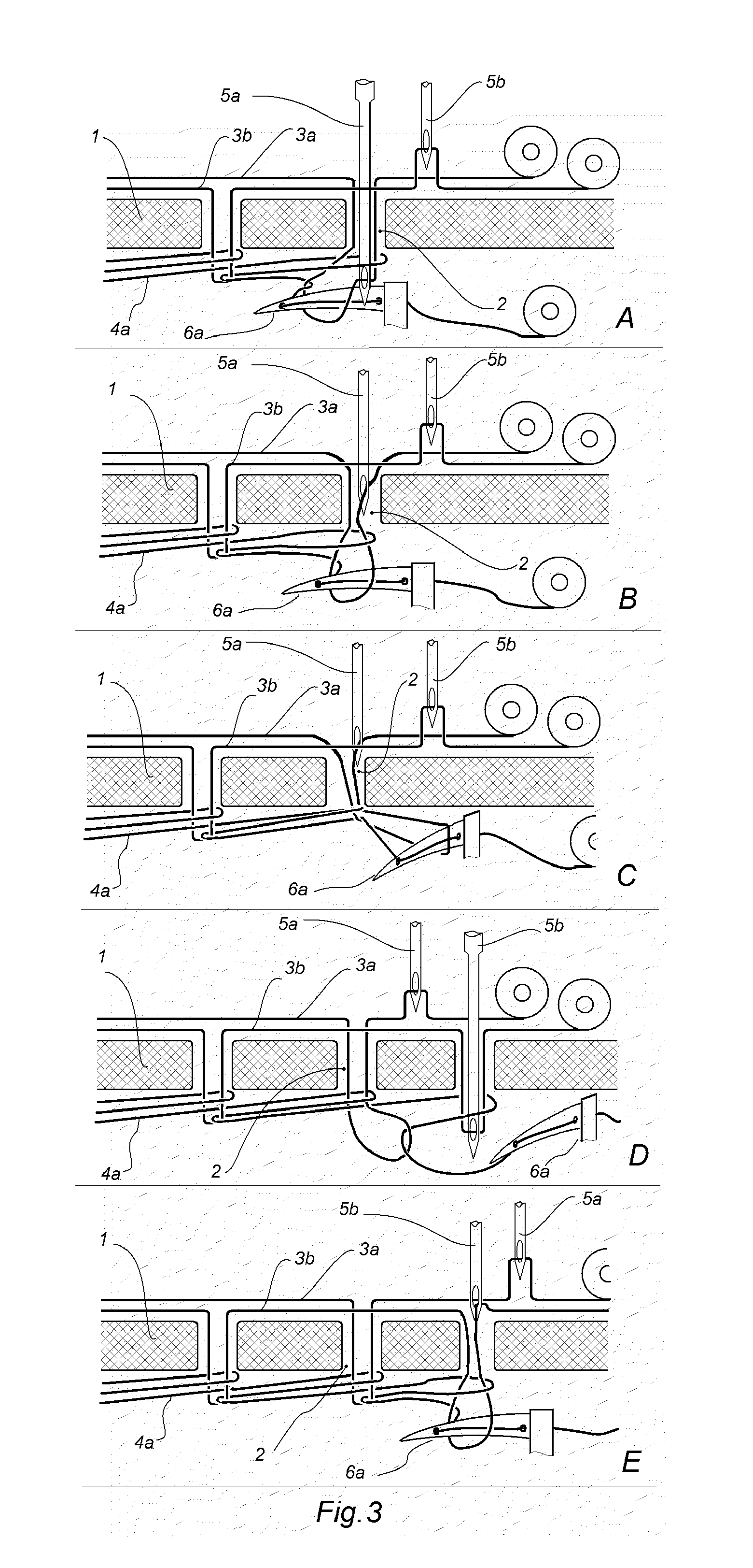
6. Manufacturing of a multi-thread single-line chain stitch line, as claimed in claim 5, by using a means for providing a desired number of cycles, where each cycle consists of the following steps (FIG. 3): After bringing a current couple into the operating position: A--passing of the top thread (3a) through material (1) by the needle (5a); passing the loop of the bottom thread (4a) by the looper (6a) through the loop of the top thread (3a); B--extracting needle (5a) out of material (1) engaging the top thread (3a) loop by looper (6a); C--shifting material (1) to extend the bottom thread (4a) loop to the next perforation point; D--passing of the top thread (3b) through material (1) by the needle (5b), further passing the needle (5b) with the top thread (3b) through the bottom thread (4a) loop; E--passing of the bottom thread (4a) by looper (6a) through the top thread (3b) loop and extracting needle (5b) out of material (1).
7. Manufacturing of a multi-thread single-line chain stitch line, as claimed in claim 6, where such means for enabling said required needle is a needle revolver; said needle revolver having needle bars located along said needle revolver's periphery and oriented along its rotation axis.
8. Manufacturing of a multi-thread single-line chain stitch line, as claimed in claim 7, where said needle revolver provides an action for intertwining said top threads between each other.
9. Manufacturing of a multi-thread single-line chain stitch line, as claimed in claim 8, where such means for enabling said required looper with one of the bottom threads is a looper revolver, which has said loopers located along the periphery of said looper revolver.
10. Manufacturing of a multi-thread single-line chain stitch line, as claimed in claim 9, where said looper revolver provides a means for intertwining said bottom threads between each other.
11. Manufacturing of a multi-thread single-line chain stitch line, as claimed in claim 8, where said current couple is formed by one of said needles and a single looper with one bottom thread loaded in it.
12. Manufacturing of a multi-thread single-line chain stitch line, as claimed in claim 1, consisting of at least three top threads, each top thread forming a loop at the material perforation point in a pre-determinable sequence, said loop being conjoined with the next loop at the next perforation point by means of a looper; no thread being loaded in said looper; said top threads being loaded in their individual needles; said individual needles being enabled in said pre-determinable sequence, which sequence is variable along the stitch line; and where said pre-determinable sequence is determined by said pre-determinable sequencing program.
13. Manufacturing of a multi-thread single-line chain stitch line, as claimed in claim 12, wherein said desired structure includes n number of top threads (3a, 3b . . . 3x), where n=3 . . . 20 and wherein said top threads on the top side of the material are independent of each other and/or intertwined between each other (as shown in FIG. 5).
14. Manufacturing of a multi-thread single-line chain stitch line, as claimed in claim 12, by use of a means for providing a desired number of cycles, where each cycle consists of the following steps (FIG. 6): A--After bringing one of said needles (5a), with one of said top threads (3a), into the operating position for said cycle: passing of the thread (3a) through material (1) to be sewn by needle (5a); engaging the thread (3a) by the looper (6a) under material (1); B--Extracting needle (5a) out of material (1) and shifting said material (1) to provide extension of the thread (3a) to the next perforation point, forming the thread (3a) loop; C--Bringing one of said needles (5b), with one of said top threads (3b), into the operating position for said cycle; D--Passing of the thread (3b) through material (1) by needle (5b) and passing the thread (3b) loop through the thread (3a) loop by the looper (6a); engaging the thread (3b) by the looper (6a) under material (1); E--Extracting needle (5b) out of said material (1) and shifting material (1) to extend the thread (3b) to the next perforation point, forming the thread (3b) loop; and F--Bringing needle (5c), with one of said top threads (3c), into the operating position for said cycle; passing of the thread (3c) through material (1) by needle (5c) and passing the thread (3c) loop through thread (3b) loop by looper (6a).
15. Manufacturing of a multi-thread single-line chain stitch line, as claimed in claim 14, where such means for enabling said required needle is a needle revolver; said needle revolver has needle bars located along said needle revolver's periphery and oriented along its rotation axis.
16. Manufacturing of a multi-thread single-line chain stitch line, as claimed in claim 15, where said needle revolver provides an action for intertwining said top threads between each other.
17. A sewing machine for manufacturing a multi-thread single-line chain stitch line, wherein at least three threads are used, said sewing machine basically comprising a means for sequentially enabling a required needle, at least one looper, a feed mechanism to feed material to be sewn, a drive mechanism to drive said means for sequentially enabling a required needle, the looper and the feed mechanism, and further comprising a means for synchronization thereof, said sewing machine providing a means for conjoining said threads at the material perforation points in a pre-determinable sequence, which sequence is variable along the stitch line, which sequence is obtained by utilizing a pre-determinable sequencing program for conjoining the threads.
18. A sewing machine for manufacturing a multi-thread single-line chain stitch line, as claimed in claim 17, wherein at least two top threads and at least one bottom thread are used, and each said top thread is loaded into its individual needle and each said bottom thread is loaded into its individual looper, said needles and said looper or loopers comprising said means for conjoining said threads.
19. A sewing machine for manufacturing a multi-thread single-line chain stitch line, as claimed in claim 18, comprising such means for sequentially enabling said required needle with one of the top threads and another means for sequentially enabling a required looper with one of the bottom threads simultaneously, providing for conjunction of one of the top threads with one of the bottom threads; said required needle and said required looper forming a current couple; wherein said current couple is chosen by pre-determinable sequencing program.
20. A sewing machine for manufacturing a multi-thread single-line chain stitch line, as claimed in claim 19, wherein such means for enabling said required needle is a needle revolver; said needle revolver has needle bars located along said needle revolver's periphery and oriented along its rotation axis; and said needle revolver provides an action for intertwining said top threads between each other.
21. A sewing machine for manufacturing a multi-thread single-line chain stitch line, as claimed in claim 20, where such means for enabling said required looper with one of the bottom threads is a looper revolver, which has said loopers located along said looper revolver's periphery.
22. A sewing machine for manufacturing a multi-thread single-line chain stitch line, as claimed in claim 20, where said current couple is formed by one of said needles and a single looper with one bottom thread loaded in it.
23. A sewing machine for manufacturing a multi-thread single-line chain stitch line, as claimed in claim 17, with at least three top threads being loaded into their individual needles, no thread being loaded in said looper; said individual needles being enabled in said pre-determinable sequence, which sequence is variable along the stitch line; and wherein said pre-determinable sequence is determined by said pre-determinable sequencing program.
24. A sewing machine for manufacturing a multi-thread single-line chain stitch line, as claimed in claim 23, where such means for enabling said required needle is a needle revolver; said needle revolver has needle bars located along said needle revolver's periphery and oriented along its rotation axis.
Description
CROSS-REFERENCES TO RELATED APPLICATIONS
[0001] Not applicable.
STATEMENT REGARDING FEDERALLY SPONSORED RESEARCH AND DEVELOPMENT
[0002] Not applicable.
BACKGROUND OF THE INVENTION AND RELATED ART STATEMENT
[0003] 1. Field of the Invention
[0004] The present invention relates to the manufacture of equipment for sewing technologies and methods for the sewing industry, the embroidered goods industry, the knitted goods industry, the leather industry and the shoe industry. The present invention comprises a technology for obtaining a multi-thread single-line chain stitch line.
[0005] 2. Description of Prior Art and Existing Problems
[0006] Existing at present, chain stitch lines (presented in U.S. Pat. Nos. 3,301,206; 3,753,410) have a limited number of threads (two threads only) being used in the line, and are limited in the variability of the structure of the stitch, which in turn limits the possibilities for adjusting the stitch line structure to the operational requirements. Likewise, the existing machines, manufacturing two-thread single-line chain stitch lines, have limited functional possibilities (as presented in U.S. Pat. Nos. 3,301,206; 3,753,410; 6,095,069).
[0007] The limited number of threads being used in the prior art strongly hinders the potential for changes in the parameters of the stitch, which are limited to changing the step of the stitch and the thread tension.
[0008] The contemporary chain stitch line used in sewing knitted goods is not very reliable, and tends to deform the seam, causing corrugation, which creates the appearance of a defect in the finished product.
[0009] Another problem in sewing technology is the optimization of stitch line properties along its length. The loads to which the stitch is exposed are different in different areas of a sewn article. In addition, the conditions of the stitch line operation are different, whereas the stitch line remains uniform along its length under the existing technology. For example, an article, such as a sleeve, is subject to various deformations in different areas--stretching at the elbow and corrugation at the bend. Also, the uniform stitch line often joins several layers of material, while the materials can be of different type (woven fabric, knitted fabric, leather, etc.). Thus, although the average properties of the uniform stitch line are intended to cover variable requirements, such factors ultimately limit the technological possibilities for creating new goods without the existing difficulties.
[0010] Further, the existing chain stitch structure results in uneven deformation under stretching, where alternating stretched and squeezed areas are created (stretched areas occur around the perforation in the material, i.e. in the point of conjunction of the top and bottom threads, while the squeezed areas occur in the interval between two perforations). Such uneven deformation of the seam causes corrugation.
[0011] Known stitch lines provide stretch ability due to the stretch ability of the threads used in the line and deformation of the sewn material.
[0012] Thus, the main drawbacks of the contemporary single-line chain stitch line, which limit its application and degrade its operational properties and appearance of the finished product, are as follows: [0013] 1. Poor functional properties, which cannot be optimized along the stitch line length, especially under conditions of complicated design and variable operating conditions; [0014] 2. Seam corrugation in the operation process; [0015] 3. Low ability to stretch; and [0016] 4. Limitations in controlling the stitch line/seam properties.
[0017] The aim of the present invention is a further improvement in the class of the chain stitch, due to the elimination of the drawbacks described above, by using the following principles: [0018] 1. The elimination of corrugations due to mutual compensation of stretch and compression zones, based on the structure of the stitch; [0019] 2. Increased stretch ability of the stitch line by replacing a rigid bond in the interval between perforations with a flexible one; [0020] 3. The introduction of duplicating bonds, thereby increasing the reliability of the stitch line; [0021] 4. Variability of the stitch structure, by varying the sequence in the conjunction of the top and bottom threads, which allows a change in the structure of the stitch along the length of the stitch line for the optimization of the operational properties of the seam in its different areas; and [0022] 5. Improved reliability of the stitch line due to intertwined top threads and/or intertwined bottom threads.
[0023] These and other objects and advantages of this invention are described in detail in the description of the invention contained herein.
BRIEF SUMMARY OF THE INVENTION
[0024] The present invention comprises variations in the manufacturing of chain stitch lines, with at least three threads involved, according to two main versions: one version consisting of top and bottom threads, which threads are conjoined at the material perforation points; and another version consists of top threads only.
[0025] In the first version, the top threads are joined with the bottom ones in a pre-determinable sequence, variable along the stitch line. This effect is obtained through the following: [0026] 1. By utilizing a pre-determinable sequencing program for conjoining the top and the bottom threads. The program is determined by the desired structure of the stitch line. [0027] 2. By the fact that each top thread is loaded into its own needle and each bottom thread into its own looper. [0028] 3. By a means for sequentially engaging a required needle and of another means for sequentially engaging a required looper simultaneously, providing for conjunction of one of the top threads with one of the bottom threads. A revolver can be used for such means in both cases. Such revolver has needle bars located along its periphery and oriented along its rotation axis, and the other revolver has loopers located along its periphery. Both revolvers are equipped with devices, providing for enabling the desired needle-looper couple, which will hereafter be called a "current couple." [0029] 4. By a means for intertwining the top threads between each other and a means for intertwining the bottom threads between each other (as referenced below).
[0030] The considered stitch line structure consists of a system of several top and several bottom threads joined through the perforations in the material. Such structure provides for a mutual compensation of stretched and squeezed areas of the material and eliminates corrugation of the seam. Another benefit is the potential for changing or transforming the structure along the length of the stitch line in the process of producing the stitch line. It permits the optimization of the properties of the seam in terms of its appearance, stretch ability, wear resistance, etc.
[0031] The sequence of interaction of the top and the bottom threads is determined by the required structure of the stitches. The sequence of interaction can be controlled mechanically or digitally. These methods of control and programming are well known and widely used--e.g., in knitwear fabrics manufacturing (U.S. Pat. Nos. 4,467,737 and 4,359,953).
[0032] The loading of every top thread into its needle and of every bottom thread into its looper can be provided by various methods used in conventional multi-thread sewing machines (U.S. Pat. Nos. 3,433,191 and 4,993,335).
[0033] A means for sequentially engaging a required needle and a means for sequentially engaging a required looper simultaneously, providing for the conjunction of one of the top threads with one of the bottom threads, is not known from the prior art. Such means could be provided in various ways. One of the ways is taught in the present invention. It comprises a needle unit (mechanism) and a looper unit (mechanism).
[0034] The needle unit comprises a revolver (needle revolver) with needle bars located along its periphery and oriented along its rotation axis. The looper unit also comprises a revolver (looper revolver), where the loopers are similarly located along its periphery. Both revolvers are equipped with a device which provides for enabling the current couple. Both revolvers are also provided with a means for turning and fixation. A Geneva wheel can be used for such purpose. (A Geneva wheel is a well-known mechanism in sewing machines; see, e.g., U.S. Pat. No. 4,702,183).
[0035] The utilization of both revolvers, due to the rotation of the needles and the loopers around the rotation axes of the respective revolvers, can provide for the respective intertwining of the top threads between each other and of the bottom threads between each other.
[0036] The second basic version of the present invention implies a multi-thread single-line chain stitch line, consisting of at least three top threads, each top thread forming a loop at the material perforation point in a predetermined sequence, such loop being conjoined with the consequent loop at the consequent perforation point by means of a looper, with no thread being loaded in the looper.
DETAILED DESCRIPTION OF THE INVENTION AND DESCRIPTION OF THE DRAWINGS
[0037] The present invention can be easily understood from the detailed description of the preferred embodiment by reference to the attached drawings.
[0038] FIG. 1: This represents a general view of the structure of a multi-thread single-line chain stitch line (one of the possible embodiments) in the formation process. The structure is obtained due to the alternating connection of each top thread with the bottom thread through perforations (2) in the material (1) with intertwining (7) of the top threads (3a, 3b). Top threads (3a, 3b) are loaded into corresponding needles (5a, 5b), and the bottom thread (4a) is loaded in the looper (6a). Loops of the top threads (3a, 3b) engage with the bottom thread (4a). With the rotation of the needles (5a, 5b) at the angular speed of revolver rotation (.omega.) the intertwining of the threads (7) is obtained.
[0039] FIG. 2: Structure of a four-thread chain stitch line comprised of two top threads (3a, 3b) and two bottom threads (4a, 4b).
[0040] FIG. 3: For better understanding the main steps in the formation of a multi-thread single-line chain stitch line, both top threads (3a, 3b) and the bottom thread (4a) are drawn at different levels for easier identification.
[0041] After bringing a current couple into the operating position:
[0042] A--passing of top thread (3a) through material (1) by a needle (5a); passing the loop of the bottom thread (4a) by the looper (6a) through the loop of the top thread (3a);
[0043] B--extracting needle (5a) out of material (1) engaging top thread (3a) loop by looper (6a);
[0044] C--shifting material (1) to extend the bottom thread loop (4a) to the next sequential perforation point;
[0045] D--passing of top thread (3b) through material (1) by a needle (5b), further passing the needle (5b) together with the top thread (3b) through the bottom thread (4a) loop;
[0046] E--passing of bottom thread (4a) by looper (6a) through the top thread (3b) loop and extracting needle (5b) out of material (1).
[0047] FIG. 4: For better understanding the main steps in the formation of a multi-thread single-line chain stitch line, the two top threads (3a, 3b) and the two bottom threads (4a, 4b) are drawn at different levels for easier identification.
[0048] After bringing a current couple into the operating position:
[0049] A--Passing of top thread (3a) through material (1) at perforation (p#1), by required needle (5a); engaging top thread (3a) by required looper (6a) with passing bottom thread (4a) into the top thread (3a) loop; thus forming the bottom thread (4a) loop inside of the top thread (3a) loop;
[0050] B--Extracting required needle (5a) out of material (1) at (p#1) and shifting material (1) to stretch the top thread (3a) loop by means of looper (6a); with this, the next current couple--needle (5b) and looper (6b)--provides interaction of top thread (3b) and bottom thread (4b); for which needle (5b) brings top thread (3b) through material (1) at (p #2), and looper (6b) brings thread (4b) through thread (3b) loop.
[0051] C--Shifting material (1) again; bringing needle (5a), which is another required needle, with the top thread (3a), which is another required thread, into the operating position for said cycle, forming another current couple with the looper (6a); with this, looper (6a) stretches thread (3a) loop to the area of the next perforation (p#3); needle (5a) brings thread (3a) through perforation (p#3) and provides interaction of thread (3a) loop by means of looper (6a) with threads (3a) and (4a); with this looper (6b) stretches thread (3b) loop.
[0052] D--Thread (3a) loop stretches thread (4a) forming an element of the stitch.
[0053] E--Looper (6a) brings thread (4a) through thread (3a) loop; with this, the next current couple (5b) and (6b) is being prepared.
[0054] F--Material (1) is shifted; with this, thread (3b) loop is stretched by looper (6b) to the area of perforation (p#4); whereas needle (5b) is bringing thread (3b) through perforation (p#4), providing interaction of thread (3b) loop with thread (4b).
[0055] G--Thread (3b) stretches thread (4b) loop to the area of perforation (p#2) forming another element of the stitch.
[0056] H--Looper (6b) brings thread (4b) through thread (3b) loop; with this, the next current couple (5a) and (6a) is formed.
[0057] I--Material (1) is shifted; looper (6a) stretches thread (3a) loop to the area of perforation (p#5), looper (6b) stretches thread (3b) loop as well; needle (5a) brings thread (3a) through perforation (p#5) and thread (4a) loop.
[0058] J--Looper (6a) throws off thread (4a) loop on needle (5a) and thread (3a).
[0059] K--Looper (6a) brings thread (4a) through thread (3a) loop; with this, the next current couple (5b) and (6b) is being formed, and the material (1) is prepared to be shifted with further repetition of the cycle described in A-G.
[0060] (Note: If intertwining is required, after each extraction of the needle the needle revolver rotates the required number of revolutions to provide intertwining).
[0061] FIG. 7: Sewing machine--front view.
[0062] FIG. 8: Sewing machine--axonometric view.
[0063] FIG. 9: Needle revolver.
[0064] FIG. 10: Needle revolver consisting of two needle modules (16a, 16b) and module mounting device (modular needle revolver) (22).
[0065] FIG. 11: Needle module.
[0066] FIGS. 1-11 disclose: 1--sewn material; 2--perforation; (p#1, p#2, p#3, p#4, p#5--numbers of perforations); 3a--first top thread; 3b--second top thread; 3c--third top thread; 4a--first bottom thread; 4b--second bottom thread; 5a--first top thread needle; 5b--second top thread needle; 5c--third top thread needle; 6a--first bottom thread looper; 6b--second bottom thread looper; 7--thread intertwining; 8--needle unit (needle revolver); 9--looper unit (looper revolver); 10--mechanism for discrete rotation of the needle revolver (e.g. Geneva wheel); 11--mechanism for discrete rotation of the looper revolver (e.g. Geneva wheel); 12--needle bar (12a--first needle bar; 12b--second needle bar); 13--needle bar engaging mechanism; 14--needle bar catching device; 15--needle bar shoulder (15a--first needle bar shoulder; 15b--second needle bar shoulder); 16a--module of needle and thread feeder mechanism of the first needle; 16b--module of needle and thread feeder mechanism of the second needle; 17--bobbin holder with bobbin; 18--thread tension regulator; 19--thread take-up; 20--thread take-up eye; 21--thread take-up drive; 22--module mounting device; 23--shaft; 24--drum; 25--module housing; 26--needle unit housing; .omega.--angular speed of revolver rotation.
[0067] The process of forming stitch lines according to the present invention can be performed by the following mechanisms and devices. The mechanism of discrete rotation of the needle revolver (10) turns needle unit (needle revolver) (8), bringing desired needle (e.g., 5a) into operating position; simultaneously, the mechanism of looper revolver discrete rotation (11) brings the desired looper (e.g., 6a) into operating position; thus, the current couple of needle (5a) and looper (6a) is enabled. With this, catching device (14) of mechanism (13) catches shoulder (15a), thus enabling needle bar (12a).
[0068] The sewing machine can be designed with: [0069] solid needle revolvers (FIG. 9); [0070] interchangeable revolvers having different numbers of needles and loopers; and with [0071] needle revolvers (modular needle revolvers) consisting of a module-mounting device (22) and the desired number of needle modules (16) (see FIG. 10 and FIG. 11).
[0072] The solid needle revolver (FIG. 9) is comprised of a cylindrical drum (24), which is driven by a rotation mechanism to make discrete rotations (10) via a shaft (23). Each needle (5) is supplied with individual needle bars (12), bobbin holders (17), thread tension regulators (18), and thread take-ups (19). The motion of the thread take-up eye (20) is synchronized with the needle bar (12) via the thread take-up drive (21).
[0073] The modular needle revolver (FIG. 10 and FIG. 11) can be designed for various module-mounting device capacities. Modules (16) are mounted on a module-mounting device (22), which is connected to the mechanism which provides for discrete rotation of the needle revolver (10). All operations are similar to the ones of the above-described solid needle revolver (FIG. 6).
[0074] The module (FIG. 11) is comprised of the casing (25) enclosing the needle bar (12) connected via the thread take-up drive (21) with the thread take-up (19). The casing (25) has a bobbin holder with bobbin (17) and thread tension regulator (18). The thread take-up drive (21) may be designed, for example, as a gear kit, transforming the motion of cogs on the needle bar (12) and the thread take-up (19).
[0075] The novelty of the present invention is in obtaining various and variable structures of chain stitch lines due to a pre-determinable conjunction of several top and several bottom threads. In the conventional chain stitch sewing machines, many methods are known for manufacturing conventional chain stitch lines. All of them are applicable to this invention with modification, providing for the individual interaction of needles and loopers, forming current couples.
[0076] While this invention has been described in terms of a specific embodiment thereof, it is to be understood that it is not limited thereto, but rather only to the extent set forth hereafter in the claims, which follow.
* * * * *
D00000
D00001
D00002
D00003
D00004
D00005
D00006
D00007
D00008
D00009
D00010
D00011
D00012

D00013

D00014

XML
uspto.report is an independent third-party trademark research tool that is not affiliated, endorsed, or sponsored by the United States Patent and Trademark Office (USPTO) or any other governmental organization. The information provided by uspto.report is based on publicly available data at the time of writing and is intended for informational purposes only.
While we strive to provide accurate and up-to-date information, we do not guarantee the accuracy, completeness, reliability, or suitability of the information displayed on this site. The use of this site is at your own risk. Any reliance you place on such information is therefore strictly at your own risk.
All official trademark data, including owner information, should be verified by visiting the official USPTO website at www.uspto.gov. This site is not intended to replace professional legal advice and should not be used as a substitute for consulting with a legal professional who is knowledgeable about trademark law.