Air conditioner for vehicle with heat pump cycle
Oomura; Mitsuyo ; et al.
U.S. patent application number 12/803372 was filed with the patent office on 2010-12-30 for air conditioner for vehicle with heat pump cycle. This patent application is currently assigned to DENSO CORPORATION. Invention is credited to Hiroyuki Hayashi, Yoshinori Ichishi, Mitsuyo Oomura, Takuya Tanihata.
| Application Number | 20100326127 12/803372 |
| Document ID | / |
| Family ID | 43379267 |
| Filed Date | 2010-12-30 |


View All Diagrams
| United States Patent Application | 20100326127 |
| Kind Code | A1 |
| Oomura; Mitsuyo ; et al. | December 30, 2010 |
Air conditioner for vehicle with heat pump cycle
Abstract
An air conditioner for a vehicle includes a vapor compression refrigeration cycle configured to have a heat pump cycle for heating air to be blown into an interior of a vehicle compartment, and a heating member for heating the air using a coolant of an internal combustion engine of the vehicle as a heat source. In the air conditioner, an operation request signal is output by an air conditioning controller to the internal combustion engine when an outside air temperature is lower than a predetermined threshold.
| Inventors: | Oomura; Mitsuyo; (Hekinan-city, JP) ; Hayashi; Hiroyuki; (Obu-city, JP) ; Tanihata; Takuya; (Nagoya-city, JP) ; Ichishi; Yoshinori; (Kariya-city, JP) |
| Correspondence Address: |
    HARNESS, DICKEY & PIERCE, P.L.C.
    P.O. BOX 828
    BLOOMFIELD HILLS
    MI
    48303
    US
|
| Assignee: | DENSO CORPORATION Kariya-city JP |
| Family ID: | 43379267 |
| Appl. No.: | 12/803372 |
| Filed: | June 25, 2010 |
| Current U.S. Class: | 62/498 |
| Current CPC Class: | B60H 2001/3292 20130101; B60H 2001/00128 20130101; F25B 41/20 20210101; F25B 47/02 20130101; F25B 6/04 20130101; B60H 1/00785 20130101; B60H 2001/3273 20130101; B60H 1/3208 20130101; B60H 1/00921 20130101 |
| Class at Publication: | 62/498 |
| International Class: | F25B 1/00 20060101 F25B001/00 |
Foreign Application Data
| Date | Code | Application Number |
|---|---|---|
| Jun 26, 2009 | JP | 2009-152095 |
Claims
1. An air conditioner for a vehicle, comprising: a vapor compression refrigeration cycle configured to have a heat pump cycle for heating air to be blown into an interior of a vehicle compartment; heating means for heating the air using a coolant of an internal combustion engine of the vehicle as a heat source; and control means for outputting an operation request signal to the internal combustion engine when an outside air temperature is lower than a predetermined threshold.
2. The air conditioner for a vehicle according to claim 1, further comprising an electric heater for heating the air by being supplied with power, wherein, when the outside air temperature is lower than the predetermined threshold, the control means outputs another operation request signal to the electric heater, in addition to the internal combustion engine.
3. The air conditioner for a vehicle according to claim 1, further comprising determining means for determining whether a possibility of fogging of a windowpane of the vehicle is high or low, wherein when the possibility of fogging of the windowpane is high, the control means sets a required number of revolutions of the internal combustion engine to be higher than that when the possibility of fogging of the windowpane is low.
4. The air conditioner for a vehicle according to claim 1, further comprising a vehicle-interior temperature setting switch for setting a temperature of an interior of the vehicle compartment by a passenger's operation, wherein, when a preset temperature set by the vehicle-interior temperature setting switch is higher than a predetermined set temperature, the control means sets a required number of revolutions of the internal combustion engine to be higher than that when the preset temperature is lower than the predetermined set temperature.
5. The air conditioner for a vehicle according to claim 1, wherein the vapor compression refrigeration cycle is configured to be switched to the heat pump cycle, and to a cooler cycle for cooling the air to be blown into the interior of the vehicle compartment, and wherein, when the outside air temperature is lower than the predetermined threshold, the control means outputs the operation request signal to the internal combustion engine, and outputs a control signal for switching to the cooler cycle, to the vapor compression refrigeration cycle.
6. The air conditioner for a vehicle according to claim 1, wherein, when the outside air temperature is lower than the predetermined threshold, the control means outputs the operation request signal to the internal combustion engine, and outputs another operation request signal of the heat pump cycle, to the vapor compression refrigeration cycle.
7. An air conditioner for a vehicle, comprising: a vapor compression refrigeration cycle including an outdoor heat exchanger for exchanging heat between refrigerant and outside air, and being configured to have a heat pump cycle for heating air to be blown into an interior of a vehicle compartment; heating means for heating the air using a coolant of an internal combustion engine as a heat source; a vehicle-interior temperature setting switch for setting a temperature of the interior of the vehicle compartment by a passenger's operation; and control means for outputting an operation request signal to the internal combustion engine when a preset temperature set by the vehicle-interior temperature setting switch is higher than a predetermined set temperature.
8. An air conditioner for a vehicle, comprising: a vapor compression refrigeration cycle including an outdoor heat exchanger for exchanging heat between refrigerant and outside air, and being configured to have a heat pump cycle for heating air to be blown into an interior of a vehicle compartment; heating means for heating the air using a coolant of an internal combustion engine as a heat source; and control means for determining whether or not an operation request signal is output to each of the vapor compression refrigeration cycle and the internal combustion engine, wherein when an outside air temperature is lower than a first predetermined temperature, the control means outputs the operation request signal to the internal combustion engine without outputting an operation request signal of the heat pump cycle to the vapor compression refrigeration cycle, when the outside air temperature is higher than the first predetermined temperature and lower than a second predetermined temperature that is higher than the first predetermined temperature, the control means outputs the operation request signal of the heat pump cycle to the vapor compression refrigeration cycle, and also outputs the operation request signal to the internal combustion engine, and when the outside air temperature is higher than the second predetermined temperature, the control means outputs the operation request signal of the heat pump cycle to the vapor compression refrigeration cycle without outputting the operation request signal to the internal combustion engine.
9. The air conditioner for a vehicle according to claim 8, wherein, in a case where both of a heating by the heat pump cycle and a heating by the heating means are performed, the control means stops the heat pump cycle when a temperature of the coolant increases to more than a predetermined temperature.
10. The air conditioner for a vehicle according to claim 8, wherein the vapor compression refrigeration cycle is configured to be switched to the heat pump cycle, and to a cooler cycle for cooling and dehumidifying the air to be blown into the interior of the vehicle compartment, and when a temperature of the coolant of the internal combustion engine increases to more than a predetermined temperature, the control means outputs an operation request signal of the cooler cycle to the vapor compression refrigeration cycle.
11. The air conditioner for a vehicle according to claim 1, wherein, when the temperature of the coolant is lower than a predetermined reference value in heating by the heating means, the control means sets a required number of revolutions of the internal combustion engine higher than that when the coolant temperature is higher than the predetermined reference.
12. An air conditioner for a vehicle, comprising: a vapor compression refrigeration cycle including a compressor for compressing and discharging a refrigerant, the vapor compression refrigeration cycle being configured to be switched to a cooler cycle for cooling air to be blown into an interior of a vehicle compartment, and to a heat pump cycle for heating the air to be blown into the interior of the vehicle compartment; and control means adapted to stop the compressor when a pressure of the refrigerant is lower than a predetermined pressure, wherein the control means set the predetermined pressure smaller in the heat pump cycle, as compared to in the cooler cycle.
13. The air conditioner for a vehicle according to claim 2, wherein the control means determines a target coolant temperature based on a target air temperature to be blown into the vehicle compartment, and decreases and corrects the target coolant temperature when the electric heater is operated.
14. The air conditioner for a vehicle according to claim 2, wherein the control means determines a target coolant temperature based on a target air temperature to be blown into the vehicle compartment, and decreases and corrects the target coolant temperature based on power consumption of the electric heater, and the control means causes a correction amount for decreasing the target coolant temperature to be increased as the power consumption of the electric heater becomes larger.
15. The air conditioner for a vehicle according to claim 1, further comprising a seat heater disposed at a seat for generating heat by being supplied with power, wherein, when the outside air temperature is lower than the predetermined threshold, the control means outputs an operation request signal to the seat heater in addition to the internal combustion engine.
16. The air conditioner for a vehicle according to claim 15, wherein the control means determines a target coolant temperature based on a target air temperature to be blown into the vehicle compartment, and decreases and corrects the target coolant temperature when the seat heater is operated.
17. The air conditioner for a vehicle according to claim 15, wherein the control means determines a target coolant temperature based on a target air temperature to be blown into the vehicle compartment, and decreases and corrects the target coolant temperature based on power consumption of the seat heater, and the control means causes a correction amount for decreasing the target coolant temperature to be increased as the power consumption of the seat heater becomes large.
18. An air conditioner for a vehicle, comprising: heating means for heating air to be blown into an interior of a vehicle compartment using a coolant of an internal combustion engine as a heat source; an electric heater for heating the air by being supplied with power; and control means for determining a target coolant temperature based on a target air temperature to be blown into the vehicle compartment, wherein the control means decreases and corrects the target coolant temperature when the electric heater is operated.
19. An air conditioner for a vehicle, comprising: heating means for heating air to be blown into an interior of a vehicle compartment using a coolant of an internal combustion engine as a heat source; an electric heater for heating the air by being supplied with power; and control means for determining a target coolant temperature based on a target air temperature to be blown into the vehicle compartment, and for decreasing and correcting the target coolant temperature based on power consumption of the electric heater, wherein the control means increases a correction amount for decreasing the target coolant temperature, as the power consumption of the electric heater becomes larger.
20. An air conditioner for a vehicle, comprising: heating means for heating air to be blown into an interior of a vehicle compartment by using a coolant of an internal combustion engine as a heat source; a seat heater disposed at a seat for generating heat by being supplied with power; and control means for determining a target coolant temperature based on a target air temperature to be blown into the vehicle compartment, wherein the control means decreases and corrects the target coolant temperature when the seat heater is operated.
21. An air conditioner for a vehicle, comprising: heating means for heating air to be blown into an interior of a vehicle compartment using a coolant of an internal combustion engine as a heat source; a seat heater disposed at a seat for generating heat by being supplied with power; and control means for determining a target coolant temperature based on a target air temperature to be blown into the vehicle compartment, and for decreasing and correcting the target coolant temperature based on power consumption of the seat heater, wherein, as the power consumption of the seat heater becomes larger, the control means increases a correction amount for decreasing the target coolant temperature.
Description
CROSS REFERENCE TO RELATED APPLICATION
[0001] This application is based on Japanese Patent Application No. 2009-152095 filed on Jun. 26, 2009, the contents of which are incorporated herein by reference in its entirety.
FIELD OF THE INVENTION
[0002] The present invention relates to an air conditioner for a vehicle, which is provided with a heat pump cycle.
BACKGROUND OF THE INVENTION
[0003] Conventionally, JP-A-10-100652 discloses regarding an air conditioner for a vehicle, which includes a heat-pump heating system for performing a heating operation by use of a heat pump, and a heater system for performing a heating operation by using hot water or heat from a heating element.
[0004] JP-A-10-100652 takes into consideration the fact that a heating efficiency of the heat-pump heating system becomes deteriorated under an atmosphere where the temperature of outside air is extremely low. Thus, at the extremely-low outside air temperature, the heating is performed by the heater system, while stopping the heat-pump heating system.
[0005] Generally, heater systems using hot water or heat from a heating element include a device for heating hot water using a combustion heater, and a PTC heater using a PTC element as a heating element.
[0006] The technique disclosed in JP-A-10-100652, however, has various problems in practical use. For example, the heater system using the combustion heater makes it difficult to sufficiently clean exhaust gas from the combustion heater, and thus cannot achieve reduction in emission. That is, provision of an exhaust emission control system or the like dedicated to the combustion heater is proposed for sufficiently cleaning the exhaust gas from the combustion heater, but is difficult to perform within the limited cost and space for mounting.
[0007] For example, the heater system using the PTC heater is difficult to ensure adequate heating capacity within the constraints of cost and mounting space.
[0008] From this point, in vehicles equipped with an engine for drive (e.g., internal combustion engine), the use of an engine coolant as a heat source for heating can achieve reduction in emission. That is, because the exhaust gas from the engine can be sufficiently cleaned by the existing exhaust emission control system, it can achieve the reduction in emission without increasing cost or space for mounting.
[0009] In a vehicle for achieving fuel consumption saving by stopping an engine, for example, in a hybrid car, an engine coolant is often at a low temperature, and thus the use of the engine coolant as a heat source for heating cannot ensure adequate heating capacity.
SUMMARY OF THE INVENTION
[0010] In view of the foregoing problems, it is an object of the present invention to improve the practical utility of an air conditioner for a vehicle, including a heat pump cycle.
[0011] It is another object of the present invention to obtain both of reduction in emission and adequate heating capacity.
[0012] It is another object of the present invention to provide an air conditioner for a vehicle, in which heating for a vehicle compartment is continuously performed even when the heating is switched from the heating by a heat pump cycle to the heating by using coolant of an internal combustion engine.
[0013] It is another object of the present invention to provide an air conditioner for a vehicle, in which an operable range of a heat pump cycle can be expanded to a low outside air temperature side, and a refrigerant shortage can be accurately detected in a cooler cycle.
[0014] It is another object of the present invention to provide an air conditioner for a vehicle, which can prevent heating capacity from being excessive, thereby effectively reducing fuel consumption.
[0015] It is another object of the present invention to provide an air conditioner for a vehicle, which can prevent warm feeling of a passenger from being excessive while fuel consumption can be improved, even when the seat heater is operated.
[0016] According to an aspect of the present invention, an air conditioner for a vehicle includes a vapor compression refrigeration cycle configured to have a heat pump cycle for heating air to be blown into an interior of a vehicle compartment, heating means for heating the air using a coolant of an internal combustion engine of the vehicle as a heat source, and control means for outputting an operation request signal to the internal combustion engine when an outside air temperature is lower than a predetermined threshold.
[0017] Accordingly, when the temperature of outside air is lower than a predetermined threshold, the operation request signal is output to the internal combustion engine, so that the heating can be performed by the heating means using the coolant of the engine as a heat source.
[0018] Thus, reduction in emission can be achieved as compared to the case of using a combustion heater. That is, since the exhaust gas from the internal combustion engine can be sufficiently, cleaned by the existing exhaust emission control system for the internal combustion engine, the air conditioner according to the invention can achieve reduction in emission without increasing cost and space for mounting.
[0019] The air conditioner according to the invention can obtain the high heating capacity as compared to the case of heating using only an electric heater, such as the PTC heater, or the case of heating by the heating means while stopping the internal combustion engine. Thus, it is possible to achieve reduction in emission and ensure the heating capacity.
[0020] For example, the air conditioner may further include an electric heater for heating the air by being supplied with power. In this case, when the outside air temperature is lower than the predetermined threshold, the control means outputs another operation request signal to the electric heater, in addition to the internal combustion engine.
[0021] Alternatively/Further, the air conditioner may further include determining means for determining whether a possibility of fogging of a windowpane of the vehicle is high or low. In this case, when the possibility of fogging of the windowpane is high, the control means sets a required number of revolutions of the internal combustion engine to be higher than that when the possibility of fogging of the windowpane is low.
[0022] Alternatively/Further, the air conditioner may further include a vehicle-interior temperature setting switch for setting a temperature of an interior of the vehicle compartment by a passenger's operation. In this case, when a preset temperature set by the vehicle-interior temperature setting switch is higher than a predetermined set temperature, the control means sets a required number of revolutions of the internal combustion engine to be higher than that when the preset temperature is lower than the predetermined set temperature.
[0023] Alternatively/Further, the vapor compression refrigeration cycle may be configured to be switched to the heat pump cycle, and to a cooler cycle for cooling the air to be blown into the interior of the vehicle compartment. In this case, when the outside air temperature is lower than the predetermined threshold, the control means outputs the operation request signal to the internal combustion engine, and outputs a control signal for switching to the cooler cycle, to the vapor compression refrigeration cycle.
[0024] Alternatively/Further, when the outside air temperature is lower than the predetermined threshold, the control means may output the operation request signal to the internal combustion engine, and may output another operation request signal of the heat pump cycle, to the vapor compression refrigeration cycle.
[0025] According to another aspect of the present invention, an air conditioner for a vehicle includes: a vapor compression refrigeration cycle including an outdoor heat exchanger for exchanging heat between refrigerant and outside air, and being configured to have a heat pump cycle for heating air to be blown into an interior of a vehicle compartment; heating means for heating the air using a coolant of an internal combustion engine as a heat source; a vehicle-interior temperature setting switch for setting a temperature of the interior of the vehicle compartment by a passenger's operation; and control means for outputting an operation request signal to the internal combustion engine when a preset temperature set by the vehicle-interior temperature setting switch is higher than a predetermined set temperature.
[0026] When the preset temperature set by the vehicle-interior temperature setting switch is high, the operating rate of the heat pump cycle becomes high. Thus, it tends to cause frost formation on the outdoor heat exchanger, thereby leading to practical problems such as degraded heat exchange capacity of the outdoor heat exchanger and reduced heating capacity of the outdoor heat exchanger.
[0027] With respect to the above problem, when the preset temperature set by the vehicle interior temperature setting switch is higher than a predetermined set temperature, the operation request signal is output to the internal combustion engine, so that the heating can be carried out by the heating means using the coolant of the internal combustion engine as a heat source. Thus, the air conditioner can stably ensure the heating capacity even when the preset temperature is high, and further improve the practical utility.
[0028] According to another aspect of the present invention, an air conditioner for a vehicle includes: a vapor compression refrigeration cycle including an outdoor heat exchanger for exchanging heat between refrigerant and outside air, and being configured to have a heat pump cycle for heating air to be blown into an interior of a vehicle compartment; heating means for heating the air using a coolant of an internal combustion engine as a heat source; and control means for determining whether or not an operation request signal is output to each of the vapor compression refrigeration cycle and the internal combustion engine. In the air conditioner, when an outside air temperature is lower than a first predetermined temperature, the control means outputs the operation request signal to the internal combustion engine without outputting an operation request signal of the heat pump cycle to the vapor compression refrigeration cycle. In contrast, when the outside air temperature is higher than the first predetermined temperature and lower than a second predetermined temperature that is higher than the first predetermined temperature, the control means outputs the operation request signal of the heat pump cycle to the vapor compression refrigeration cycle, and also outputs the operation request signal to the internal combustion engine. Furthermore, when the outside air temperature is higher than the second predetermined temperature, the control means outputs the operation request signal of the heat pump cycle to the vapor compression refrigeration cycle without outputting the operation request signal to the internal combustion engine. Thus, even when the heating is switched from the heating by the heat pump cycle to the heating by using the coolant of the internal combustion engine, the heating can be continuously performed.
[0029] For example, in a case where both of a heating by the heat pump cycle and a heating by the heating means are performed, the control means stops the heat pump cycle when a temperature of the coolant increases to more than a predetermined temperature.
[0030] Furthermore/Alternatively, the vapor compression refrigeration cycle may be configured to be switched to the heat pump cycle, and to a cooler cycle for cooling and dehumidifying the air to be blown into the interior of the vehicle compartment. In this case, when a temperature of the coolant of the internal combustion engine increases to more than a predetermined temperature, the control means may output an operation request signal of the cooler cycle to the vapor compression refrigeration cycle.
[0031] In any one air conditioner of the above-described invention, when the temperature of the coolant is lower than a predetermined reference value in heating by the heating means, the control means sets a required number of revolutions of the internal combustion engine higher than that when the coolant temperature is higher than the predetermined reference.
[0032] According to another aspect of the present invention, an air conditioner for a vehicle includes: a vapor compression refrigeration cycle including a compressor for compressing and discharging a refrigerant, the vapor compression refrigeration cycle being configured to be switched to a cooler cycle for cooling air to be blown into an interior of a vehicle compartment, and to a heat pump cycle for heating the air to be blown into the interior of the vehicle compartment; and control means adapted to stop the compressor when a pressure of the refrigerant is lower than a predetermined pressure. Furthermore, the control means set the predetermined pressure smaller in the heat pump cycle, as compared to in the cooler cycle. Thus, an operable range of the heat pump cycle can be expanded to a low outside air temperature side, and a refrigerant shortage can be accurately detected in a cooler cycle.
[0033] In any air conditioner according to the above-described invention, the control means may determine a target coolant temperature based on a target air temperature to be blown into the vehicle compartment, and may decrease and correct the target coolant temperature when the electric heater is operated. Alternatively, the control means may determine a target coolant temperature based on a target air temperature to be blown into the vehicle compartment, and may decrease and correct the target coolant temperature based on power consumption of the electric heater. In this case, the control means may cause a correction amount for decreasing the target coolant temperature to be increased as the power consumption of the electric heater becomes larger. Alternatively, the air conditioner for a vehicle may further include a seat heater disposed at a seat for generating heat by being supplied with power. In this case, when the outside air temperature is lower than the predetermined threshold, the control means outputs an operation request signal to the seat heater in addition to the internal combustion engine. Thus, a passenger's feeling can be effectively improved even when the temperature of the coolant is relatively low.
[0034] For example, in this case, the control means may determine a target coolant temperature based on a target air temperature to be blown into the vehicle compartment, and decreases and corrects the target coolant temperature when the seat heater is operated. The control means may determine a target coolant temperature based on a target air temperature to be blown into the vehicle compartment, and may decrease and correct the target coolant temperature based on power consumption of the seat heater, and the control means may cause a correction amount for decreasing the target coolant temperature to be increased as the power consumption of the seat heater becomes large.
[0035] According to another aspect of the present invention, an air conditioner for a vehicle includes: heating means for heating air to be blown into an interior of a vehicle compartment using a coolant of an internal combustion engine as a heat source; an electric heater for heating the air by being supplied with power; and control means for determining a target coolant temperature based on a target air temperature to be blown into the vehicle compartment. In the air conditioner, the control means decreases and corrects the target coolant temperature when the electric heater is operated. Thus, it can prevent heating capacity from being excessive, thereby effectively reducing fuel consumption.
[0036] According to another aspect of the present invention, an air conditioner for a vehicle includes: heating means for heating air to be blown into an interior of a vehicle compartment using a coolant of an internal combustion engine as a heat source; an electric heater for heating the air by being supplied with power; and control means for determining a target coolant temperature based on a target air temperature to be blown into the vehicle compartment, and for decreasing and correcting the target coolant temperature based on power consumption of the electric heater. In the air conditioner, the control means increases a correction amount for decreasing the target coolant temperature, as the power consumption of the electric heater becomes larger. Thus, it can prevent heating capacity from being excessive, thereby effectively reducing fuel consumption.
[0037] According to another aspect of the present invention, an air conditioner for a vehicle includes: heating means for heating air to be blown into an interior of a vehicle compartment by using a coolant of an internal combustion engine as a heat source; a seat heater disposed at a seat for generating heat by being supplied with power; and control means for determining a target coolant temperature based on a target air temperature to be blown into the vehicle compartment. In the air conditioner, the control means decreases and corrects the target coolant temperature when the seat heater is operated. Thus, when the seat heater is operated, the warm feeling given to the passenger can be improved while the fuel consumption can be improved.
[0038] According to another aspect of the present invention, an air conditioner for a vehicle includes: heating means for heating air to be blown into an interior of a vehicle compartment using a coolant of an internal combustion engine as a heat source; a seat heater disposed at a seat for generating heat by being supplied with power; and control means for determining a target coolant temperature based on a target air temperature to be blown into the vehicle compartment, and for decreasing and correcting the target coolant temperature based on power consumption of the seat heater. In the air conditioner, as the power consumption of the seat heater becomes larger, the control means increases a correction amount for decreasing the target coolant temperature. Thus, when the seat heater is operated, it can prevent warm feeling of a passenger from being excessive, while the fuel consumption can be improved.
BRIEF DESCRIPTION OF THE DRAWINGS
[0039] Additional objects and advantages of the present invention will be more readily apparent from the following detailed description of preferred embodiments when taken together with the accompanying drawings. In which:
[0040] FIG. 1 is an entire configuration diagram showing an air conditioner for a vehicle with a refrigerant circuit in a cooling mode according to a first embodiment of the invention;
[0041] FIG. 2 is an entire configuration diagram showing the air conditioner for a vehicle with a refrigerant circuit in a heating mode according to the first embodiment;
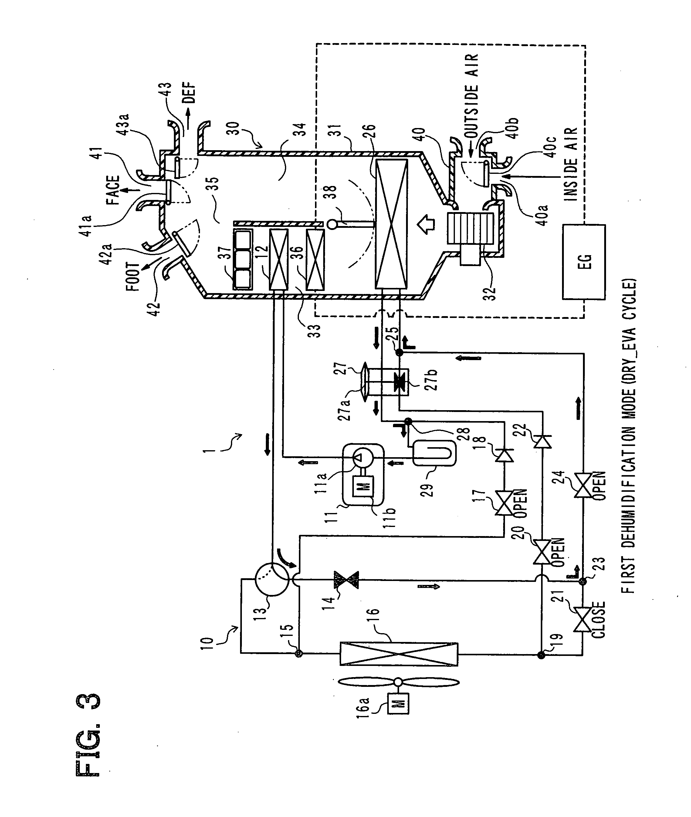
[0042] FIG. 3 is an entire configuration diagram showing the air conditioner for a vehicle with a refrigerant circuit in a first dehumidification mode according to the first embodiment;
[0043] FIG. 4 is an entire configuration diagram showing the air conditioner for a vehicle with a refrigerant circuit in a second dehumidification mode according to the first embodiment;
[0044] FIG. 5 is a block diagram showing an electric controller of the air conditioner for a vehicle in the first embodiment;
[0045] FIG. 6 is a flowchart showing control performed by the air conditioner for a vehicle in the first embodiment;
[0046] FIG. 7 is a flowchart showing a detail control at step S14 of FIG. 6;
[0047] FIG. 8 is a diagram showing dehumidifying capacity and heating capacity in respective operation modes of the air conditioner for a vehicle in the first embodiment;
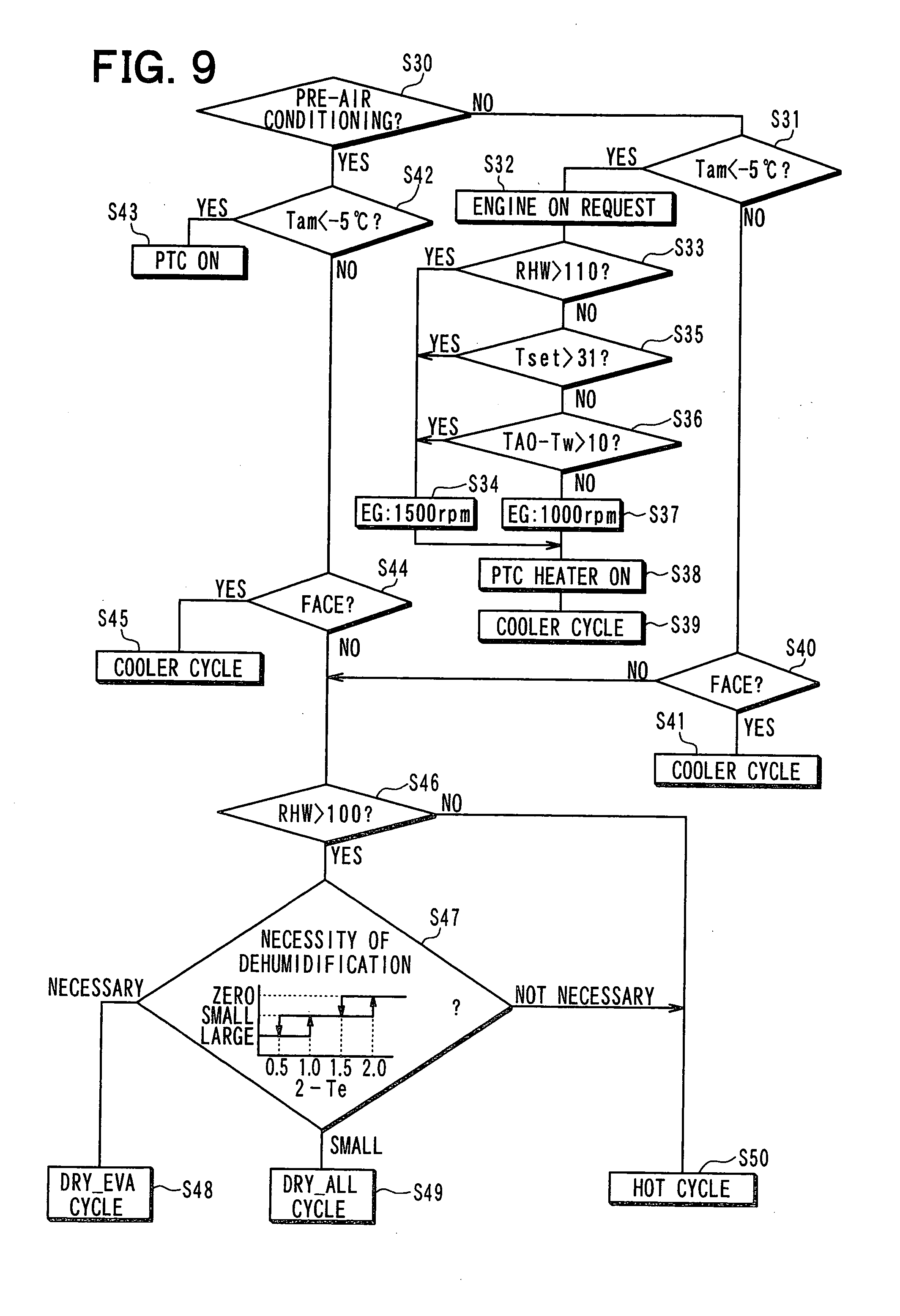
[0048] FIG. 9 is a flowchart showing a part of the control performed by the air conditioner for a vehicle in the first embodiment;
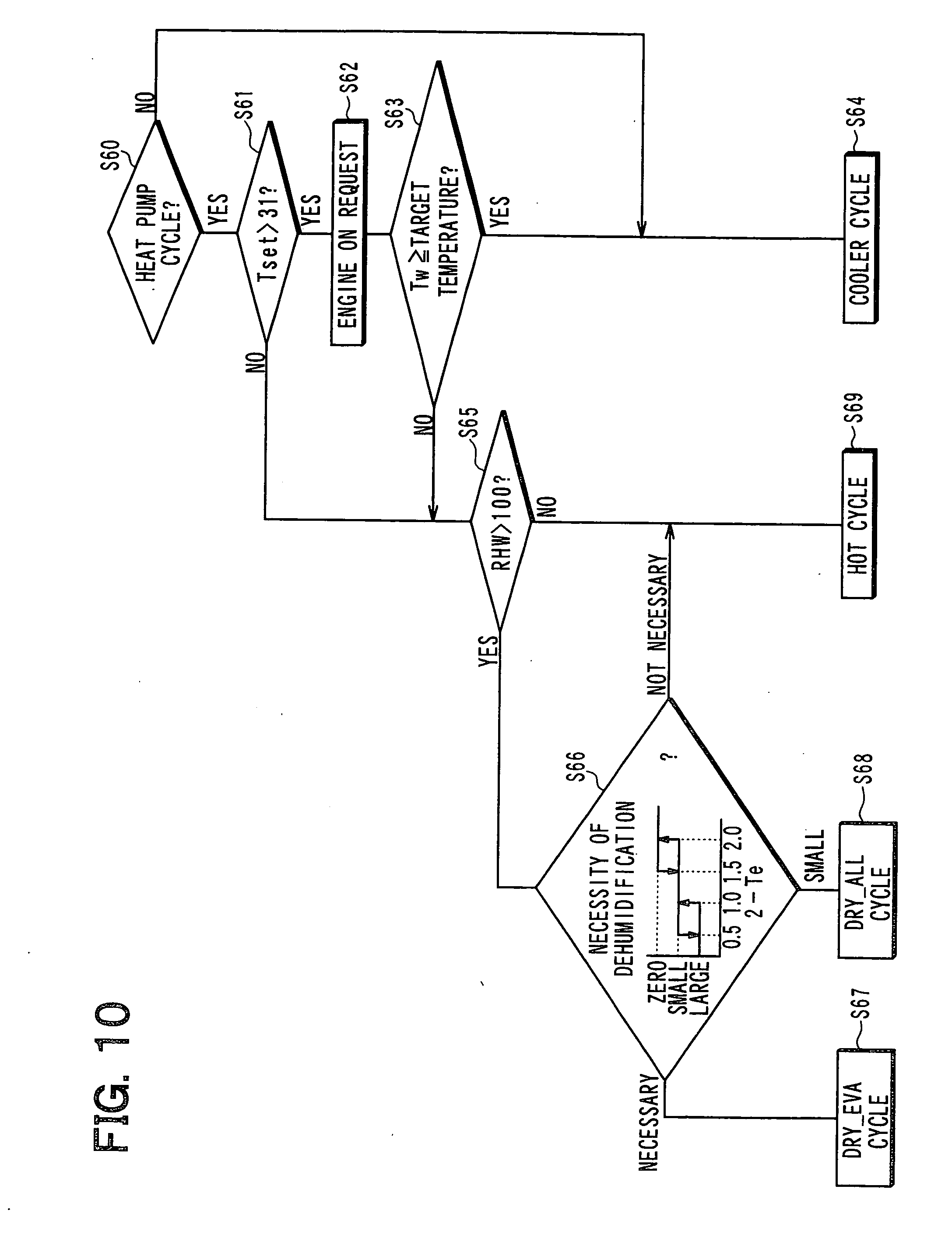
[0049] FIG. 10 a flowchart showing a part of control performed by an air conditioner for a vehicle according to a second embodiment of the invention;
[0050] FIG. 11 a flowchart showing a part of control performed by an air conditioner for a vehicle according to a third embodiment of the invention;
[0051] FIG. 12 a flowchart showing a part of control performed by an air conditioner for a vehicle according to a fourth embodiment of the invention;
[0052] FIG. 13A a flowchart showing a part of control performed by an air conditioner for a vehicle according to a fifth embodiment of the invention, and FIGS. 13B and 13C are diagrams showing respectively examples of the rule of the fuzzy theory, for determining change amounts .DELTA.fC and .DELTA.fH;
[0053] FIG. 14 a flowchart showing a part of control performed by an air conditioner for a vehicle according to a sixth embodiment of the invention;
[0054] FIG. 15 a flowchart showing a part of control performed by an air conditioner for a vehicle according to a seventh embodiment of the invention;
[0055] FIG. 16 a flowchart showing a part of control performed by an air conditioner for a vehicle according to an eighth embodiment of the invention; and
[0056] FIG. 17 a flowchart showing a part of control performed by an air conditioner for a vehicle according to a ninth embodiment of the invention.
DETAILED DESCRIPTION OF THE PREFERRED EMBODIMENTS
[0057] Embodiments for carrying out the present invention will be described hereafter referring to drawings. In the embodiments, a part that corresponds to a matter described in a preceding embodiment may be assigned with the same reference numeral, and redundant explanation for the part may be omitted. When only a part of a configuration is described in an embodiment, another preceding embodiment may be applied to the other parts of the configuration. The parts may be combined even if it is not explicitly described that the parts can be combined. The embodiments may be partially combined even if it is not explicitly described that the embodiments can be combined, provided there is no harm in the combination.
First Embodiment
[0058] A first embodiment of the invention will be described below with reference to FIGS. 1 to 9. In the present embodiment, an air conditioner for a vehicle of the invention is applied to the so-called hybrid car which obtains a driving force for a vehicle traveling from an internal combustion engine (engine) EG and an electric motor for traveling. FIGS. 1 to 4 show an entire configuration diagram of an air conditioner 1 for a vehicle, according to the first embodiment and the following embodiments described later.
[0059] The air conditioner for a vehicle includes a vapor compression refrigeration cycle 10 which can switch among refrigerant circuits in a cooling mode (COOL cycle) for cooling the vehicle interior, in a heating mode (HOT cycle) for heating the vehicle interior, and in a first dehumidification mode (DRY_EVA cycle) and in a second dehumidification mode (DRY_ALL cycle) for dehumidifying the vehicle interior. FIGS. 1 to 4 indicate the flows of refrigerant in the cooling mode, the heating mode, the first dehumidification mode, and the second dehumidification mode by respective solid lines.
[0060] The cooling mode is an operation mode causing the refrigeration cycle 10 to be in the COOL cycle, so as to have cooling capacity and dehumidification capacity. Thus, the cooling mode can be represented as a cooling dehumidification mode.
[0061] The heating mode and the first and second dehumidification modes are modes in which the refrigeration cycle 10 is operated as a heat pump cycle. In the three modes using the heat pump cycle, the heating mode has a high heating capacity but does not have the dehumidification capacity. Thus, the heating mode is used in a heat pump cycle without dehumidifying.
[0062] In the three modes using the heat pump cycle, the first and second dehumidification modes have the dehumidification capacity, but have the heating capacity lower than that in the heating mode. Thus, the first and second dehumidification modes are operated as a heat pump cycle having the dehumidification capacity.
[0063] The first dehumidification mode is a dehumidification mode which puts higher priority on a dehumidification capacity than a heating capacity. The second dehumidification mode is a dehumidification mode which puts higher priority on a heating capacity than the dehumidification capacity. Therefore, the first dehumidification mode can be represented by a low-temperature dehumidification mode or a single dehumidification mode, and the second dehumidification mode can be represented by a high-temperature dehumidification mode or a dehumidification heating mode.
[0064] FIG. 8 shows the dehumidification capacity and the heating capacity in cooling mode, the heating mode, the first and second dehumidification modes. That is, in the cooling mode, the dehumidification capacity is large, but there is no the heating capacity. Thus, when the cooling mode is selected in the heating, a heating means (e.g., heater core 36, PTC heater 37 described latter) other than the refrigeration cycle 10 is combined to be operated.
[0065] In the heating mode, the heating capacity is large, but there is no the dehumidification capacity. In the first dehumidification mode, the dehumidification capacity is middle, but the heating capacity is small. In the second dehumidification mode, the dehumidification capacity is small, but the heating capacity is middle.
[0066] The refrigeration cycle 10 includes a compressor 11, an indoor condenser 12 and an indoor evaporator 26 serving as an indoor heat exchanger, a thermal expansion valve 27 and a fixed throttle 14 serving as decompression means for decompressing and expanding refrigerant, and a plurality of (in the present embodiment, five) electromagnetic valves 13, 17, 20, 21, 24, and the like serving as refrigerant circuit switching means.
[0067] The refrigeration cycle 10 employs a normal flon-based refrigerant as the refrigerant, and thus forms a subcritical refrigeration cycle in which high-pressure side refrigerant pressure does not exceed the critical pressure of the refrigerant. Further, a refrigerating machine oil for lubricating the compressor 11 is mixed with the refrigerant. The refrigerating machine oil circulates through the cycle together with the refrigerant.
[0068] The compressor 11 is positioned in an engine room, and is to suck, compress, and discharge the refrigerant in the refrigeration cycle 10. The compressor is an electric compressor which drives a fixed displacement compressor mechanism 11a having a fixed discharge capacity by using an electric motor 11b. Specifically, various types of compressor mechanisms, such as a scroll type compressor mechanism, or a vane compressor mechanism, can be employed as the fixed displacement compressor mechanism 11a.
[0069] The electric motor 11b is an AC motor whose operation (number of revolutions) is controlled by an AC voltage output from an inverter 61. The inverter 61 outputs an AC voltage of a frequency corresponding to a control signal output from an air conditioning controller 50 to be described later. The control of the number of revolutions changes a refrigerant discharge capacity of the compressor 11. Thus, the electric motor 11b serves as discharge capacity changing means of the compressor 11.
[0070] The refrigerant discharge side of the compressor 11 is coupled to the refrigerant inlet side of the indoor condenser 12. The indoor condenser 12 is disposed in a casing 31 forming an air passage through which air flows into the vehicle interior in an indoor air conditioning unit 30 of the air conditioner for a vehicle. The indoor condenser 12 is a heat exchanger for heating the air by exchanging heat between the refrigerant flowing therethrough and the air having passed through an indoor evaporator 26 to be described later. The details of the indoor air conditioning unit 30 will be described later.
[0071] The refrigerant outlet side of the indoor condenser 12 is coupled to an electric three-way valve 13. The electric three-way valve 13 is refrigerant circuit switching means its operation is controlled by a control voltage output from the air conditioning controller 50.
[0072] More specifically, in an energization state with power supplied, the electric three-way valve 13 performs switching to a refrigerant circuit coupling between the refrigerant outlet side of the indoor condenser 12 and the refrigerant inlet side of the fixed throttle 14. In a non-energization state without power supplied, the three-way valve 13 performs switching to a refrigerant circuit coupling between the refrigerant outlet side of the indoor condenser 12 and one of refrigerant inlet and outlet ports of a first three-way joint 15.
[0073] The fixed throttle 14 is decompression means for heating and dehumidifying, and is adapted to decompress and expand the refrigerant flowing from the electric three-way valve 13 in the heating mode, and the first and second dehumidification modes. For example, a capillary tube, an orifice, or the like can be adapted as the fixed throttle 14. Alternatively, the decompression means for heating and dehumidifying may employ an electric variable throttle mechanism whose throttle passage area is adjusted by a control signal output from the air conditioning controller 50. The refrigerant outlet side of the fixed throttle 14 is coupled to one of the refrigerant inflow/outlet ports of a three-way joint 23 to be described later.
[0074] The first three-way joint 15 includes three refrigerant inlet/outlet ports, and serves as a branch portion for branching a refrigerant flow path. Such a three-way joint may be provided by connecting refrigerant pipes, or by forming a plurality of refrigerant passages in a metal block or resin block. Another refrigerant inlet/outlet port of the first three-way joint 15 is coupled to one of the refrigerant inlet/outlet ports of the outdoor heat exchanger 16, and a further refrigerant inlet/outlet port of the three-way joint 15 is coupled to the refrigerant inlet side of the low-voltage electromagnetic valve 17.
[0075] The low-voltage electromagnetic valve 17 includes a valve body for opening and closing a refrigerant flow path, and a solenoid (coil) for driving the valve body. The electromagnetic valve 17 is refrigerant circuit switching means whose operation is controlled by a control voltage output from the air conditioning controller 50. More specifically, the low-voltage electromagnetic valve 17 is the so-called normally-closed type opening and closing valve which is opened upon energization and closed upon non-energization.
[0076] The refrigerant outlet side of the low-voltage electromagnetic valve 17 is coupled to one of the refrigerant inlet/outlet ports of a fifth three-way joint 28 to be described later via a first check valve 18. The first check valve 18 allows only the refrigerant to flow from the low-voltage electromagnetic valve 17 to the fifth three-way joint 28.
[0077] The outdoor heat exchanger 16 is disposed in the engine room, and is to exchange heat between the refrigerant flowing therethrough and air (i.e., outside air) outside a vehicle compartment blown from a blower fan 16a. The blower fan 16a is an electric blower whose number of revolutions (amount of air) is controlled by a control voltage output from the air conditioning controller 50.
[0078] The blower fan 16a of the present embodiment blows the outside air not only to the outdoor heat exchanger 16, but also to a radiator (not shown) for radiating heat from coolant of the engine EG. Specifically, the air outside the vehicle compartment blown from the blower fan 16a flows through the outdoor heat exchanger 16 and the radiator in that order.
[0079] In coolant circuits indicated by broken lines shown in FIGS. 1 to 4, a coolant pump (not shown) is provided for allowing a coolant to circulate therethrough. The coolant pump is an electric water pump whose number of revolutions (amount of coolant circulating) is controlled by a control voltage output from the air conditioning controller 50.
[0080] The other one of the refrigerant inlet/outlet ports of the outdoor heat exchanger 16 is coupled to one of the refrigerant inlet/outlet ports of the second three-way joint 19. The basic structure of the second three-way joint 19 is the same as that of the first three-way joint 15. Another one of the refrigerant inlet/outlet ports of the second three-way joint 19 is coupled to the refrigerant inlet side of the high-voltage electromagnetic valve 20, and a further one of the refrigerant inlet/outlet ports is coupled to one of the refrigerant inlet and outlet ports of the electromagnetic valve 21 for interruption of the heat exchanger.
[0081] The high-voltage electromagnetic valve 20 and the heat-exchanger interruption electromagnetic valve 21 are refrigerant circuit switching means whose operation is controlled by a control voltage output from the air conditioning controller 50. The basic structure of the valves 20 and 21 is the same as that of the low-voltage electromagnetic valve 17. The high-voltage electromagnetic valve 20 and the heat-exchanger interruption electromagnetic valve 21 are formed as the so-called normally-opened type opening and closing valve designed to be closed upon energization and opened upon non-energization.
[0082] The refrigerant outlet side of the high-voltage electromagnetic valve 20 is coupled to an inlet of a throttle mechanism of a thermal expansion valve 27 to be described later via a second check valve 22. The second check vale 22 allows only the refrigerant to flow from the high-voltage electromagnetic valve 20 to the thermal expansion valve 27.
[0083] The other one of the refrigerant inlet/outlet ports of the heat exchanger interruption electromagnetic vale 21 is coupled to one of the refrigerant inlet/outlet ports of the third three-way joint 23. The basic structure of the third three-way joint 23 is the same as that of the first three-way joint 15. Another one of the refrigerant inlet/outlet ports of the third three-way joint 23 is coupled to the refrigerant outlet side of the fixed throttle 14 as mentioned above. A further one of the refrigerant inlet/outlet ports of the joint 23 is coupled to the refrigerant inlet side of the dehumidifying electromagnetic valve 24.
[0084] The dehumidifying electromagnetic valve 24 is refrigerant circuit switching means whose operation is controlled by a control voltage output from the air conditioning controller 50. The basic structure of the valve 24 is the same as that of the low-voltage electromagnetic valve 17. The dehumidifying electromagnetic valve 24 also serves as a normally-closed type opening and closing valve. The refrigerant circuit switching means of the present embodiment is comprised of (five) electromagnetic valves which are adapted to be brought into a predetermined opened or closed state when the supply of power is stopped. The electromagnetic valves include the electric three-way valve 13, the low-voltage electromagnetic valve 17, the high-voltage electromagnetic valve 20, the heat exchanger interruption electromagnetic valve 21, and the dehumidifying electromagnetic valve 24.
[0085] The refrigerant outlet side of the dehumidifying electromagnetic valve 24 is coupled to one of the refrigerant inlet/outlet ports of a fourth three-way joint 25. The basic structure of the fourth three-way joint 25 is the same as that of the first three-way joint 15. Another one of the refrigerant inlet/outlet ports of the fourth three-way joint 25 is coupled to the outlet side of the throttle mechanism of the thermal expansion valve 27, and a further one of the refrigerant inlet/outlet ports is coupled to the refrigerant inlet side of the indoor evaporator 26.
[0086] The indoor evaporator 26 is disposed on the upstream side of the air flow of the indoor condenser 12 in a casing 31 of the indoor air conditioning unit 30. The indoor evaporator 26 is a heat exchanger for cooling air by exchanging heat between the air and the refrigerant flowing therethrough.
[0087] The refrigerant outlet side of the indoor evaporator 26 is coupled to the inlet side of a temperature sensing portion of the thermal expansion valve 27. The thermal expansion valve 27 is decompression means for cooling which decompresses and expands the refrigerant flowing from the inlet of the throttle mechanism thereinto to allow the refrigerant to flow outward from the outlet of the throttle mechanism.
[0088] More specifically, the thermal expansion valve 27 used in the present embodiment is an internal pressure equalizing expansion valve which accommodates in one housing, a temperature sensing portion 27a and a variable throttle mechanism 27b. The temperature sensing portion 27a is provided for detecting the degree of superheat of the refrigerant on the outlet side of the indoor evaporator 26 based on the temperature and pressure of the refrigerant on the outlet side of the indoor evaporator 26. The variable throttle mechanism 27b is provided for adjusting a throttle passage area (refrigerant flow rate) based on a displacement of the temperature sensing portion 27a such that the superheat degree of the refrigerant on the outlet side of the evaporator 26 is in a predetermined range.
[0089] The outlet side of the temperature sensing portion of the thermal expansion valve 27 is coupled to one of the refrigerant inlet and outlet ports of the fifth three-way joint 28. The basic structure of the fifth three-way joint 28 is the same as that of the first three-way joint 15. As mentioned above, another one of the refrigerant inlet and outlet ports of the fifth three-way joint 28 is coupled to the refrigerant outlet side of the fifth check valve 18, and a further one of the refrigerant inlet and outlet ports is coupled to the refrigerant inlet side of an accumulator 29.
[0090] The accumulator 29 is a low-pressure side vapor-liquid separator which is adapted to separate the refrigerant flowing thereinto from the fifth three-way joint 28 and to store the excessive refrigerant. The vapor-phase refrigerant outlet of the accumulator 29 is coupled to a refrigerant suction port of the compressor 11.
[0091] Now, the indoor air conditioning unit 30 will be described below. The indoor air conditioning unit 30 is disposed inside a gauge board (i.e., instrument panel) at the foremost part of the interior of the vehicle. The unit 30 accommodates in the casing 31 serving as an outer envelope, a blower 32, the above-mentioned indoor evaporator 26, the indoor condenser 12, a heater core 36, a PTC heater 37, and the like.
[0092] The casing 31 forms an air passage of air blown into the vehicle interior. The casing 31 is formed of resin (for example, polypropylene) having some degree of elasticity and excellent strength. An inside/outside air switching box 40 for switching between an inside air (i.e., air inside the vehicle compartment) and an outside air (i.e., air outside the vehicle compartment) to introduce the selected air is disposed on the most upstream side of the air flow in the casing 31.
[0093] More specifically, the inside/outside air switching box 40 is provided with an inside air inlet 40a for introducing the inside air into the casing 31, and an outside air inlet 40b for introducing the outside air thereinto. The inside/outside air switching box 40 has therein an inside/outside air switching door 40c for changing the ratio of an amount of the inside air to an amount of the outside air by continuously adjusting opening areas of the inside air inlet 40a and outside air inlet 40b.
[0094] The inside/outside air switching door 40c serves as air amount ratio changing means for switching among suction port modes to change the ratio of the inside air amount to the outside air amount introduced into the casing 31. More specifically, the inside/outside air switching door 40c is driven by an electric actuator 62 for the inside/outside air switching door 40c. The electric actuator 62 has its operation controlled by a control signal output from the air conditioning controller 50.
[0095] The suction port modes include an inside air mode, an outside air mode, and an inside and outside air mixing mode. In the inside air mode, the inside air is introduced into the casing 31 by fully opening the inside air inlet 40a, while completely closing the outside air inlet 40b. In the outside air mode, the outside air is introduced into the casing 31 by completely closing the inside air inlet 40a, while fully opening the outside air inlet 40b. In the inside and outside air mixing mode, the ratio of an introduced amount of inside air to an introduced amount of outside air is continuously changed by adjusting the opening areas of the inside air inlet 40a and outside air inlet 40b in a continuous manner between the inside air mode and the outside air mode.
[0096] The blower 32 for blowing air sucked via the inside/outside air switching box 40 into the vehicle interior is disposed on the downstream side of the air flow of the inside/outside air switching box 40. The blower 32 is an electric blower which includes a centrifugal multiblade fan (e.g., sirocco fan) driven by an electric motor, and whose number of revolutions is controlled by the control voltage output from the air conditioning controller 50, thereby controlling air blowing amount.
[0097] The indoor evaporator 26 is disposed on the downstream side of the air flow of the blower 32. Further, a heating air passage 33 for allowing air passing through the indoor evaporator 26 to flow therethrough, an air passage including a cool air bypath passage 34, and a mixing space 35 for mixing air from the heating air passage 33 and the cool air bypass passage 34 are formed on the downstream side of the air flow of the indoor evaporator 26.
[0098] In the heating air passage 33, the heater core 36, the indoor condenser 12, and the PTC heater 37 are arranged in that order along the direction of air flow so as to serve as heating means for heating air passing through the indoor evaporator 26. The heater core 36 and the PTC heater 37 can be adapted as a heating means for heating air by using a heat source other than the refrigerant.
[0099] The heater core 36 is a heat exchanger for heating air having passed through the indoor evaporator 26 by exchanging heat between coolant of the engine EG for outputting a driving force for vehicle traveling, and air having passed through the indoor evaporator 26.
[0100] The PTC heater 37 is an electric heater with a PTC element (positive characteristic thermistor) which produces heat by being supplied with power thereby to heat air having passed through the indoor condenser 12. The air conditioner is provided with a plurality of (specifically, three) PTC heaters 37. The air conditioning controller 50 controls the heating capacity of the whole PTC heaters 37 by changing the number of the PTC heaters 37 energized.
[0101] On the other hand, the cool air bypass passage 34 is an air passage for allowing the air having passed through the indoor evaporator 26 to be introduced into the mixing space 35 without passing through the heater core 36, the indoor condenser 12, and the PTC heater 37. Thus, the temperature of the air mixed in the mixing space 35 is changed by the ratio of the amount of air passing through the heating air passage 33 to the amount of air passing through the cool bypass passage 34.
[0102] In the present embodiment, an air mix door 38 is provided for continuously changing the ratio of the amount of cool air flowing into the heating air passage 33 to that of cool air flowing into the cool air bypass passage 34, on the downstream side of the air flow of the indoor evaporator 26, and on the inlet sides of the heating air passage 33 and the cool air bypass passage 34.
[0103] Thus, the air mix door 38 serves as temperature adjustment means for adjusting the temperature of air in the mixing space 35, thereby adjusting temperature of air blown into the vehicle interior. More specifically, the air mix door 38 is driven by an electric actuator 63 for the air mix door. The electric actuator 63 has its operation controlled by a control signal output from the air conditioning controller 50.
[0104] Air outlets 41-43 for blowing the air, whose temperature is adjusted, from the mixing space 35 into the vehicle interior as a space to be cooled are disposed on the most downstream side of the air flow in the casing 31. The air outlets 41-43 include; specifically, a face air outlet 41 from which conditioned air is blown toward an upper body of a passenger in the vehicle compartment, a foot air outlet 42 from which conditioned air is blown toward a foot of the passenger, and a defroster air outlet 43 from which conditioned air is blown toward the inner side of a front windowpane of the vehicle.
[0105] A face door 41a for adjusting the area of an opening of the face air outlet 41 is positioned on the upstream side of the air flow of the face air outlet. A foot door 42a for adjusting the area of an opening of the foot air outlet 42 is positioned on the upstream side of the air flow of the foot air outlet 42. A defroster door 43a for adjusting the area of an opening of the defroster air outlet 43 is positioned on the upstream side of the air flow of the defroster air outlet 43.
[0106] The face door 41a, the foot door 42a, and the defroster door 43a serve as air outlet mode switching means for switching among air outlet modes, and are rotatably operated in connection and cooperation with the electric actuator 64 for driving the air outlet mode door via a link mechanism (not shown). The electric actuator 64 also has its operation controlled by the control signal output from the air conditioning controller 50.
[0107] The air outlet modes include a face mode, a bi-level mode, a foot mode, and a foot/defroster mode. In the face mode, air is blown from the face air outlet 41 toward the upper body of the passenger in the vehicle compartment by fully opening the face air outlet 41. In the bi-level mode, air is blown toward the upper body and foot of the passenger in the vehicle compartment by fully opening both of the face air outlet 41 and the foot air outlet 42. In the foot mode, air is blown mainly from the foot air outlet 42 by fully opening the foot air outlet 42, while opening the defroster air outlet 43 to a small degree of opening. In the foot/defroster mode, air is blown from both the foot air outlet 42 and the defroster air outlet 43 by opening the foot air outlet 42 and the defroster air outlet 43 to the same degree.
[0108] An air outlet mode switch 60c of an operation panel 60 to be described later is manually operated by the passenger, so that the defroster air outlet 43 is fully opened thereby to enable setting of a defroster mode for blowing air from the defroster air outlet 43 toward the inner face of the front windowpane of the vehicle.
[0109] When the foot mode is selected as the air outlet mode, air is blown from at least the foot air outlet 42. When the foot/defroster mode or the defroster mode is selected, a flow amount ratio of air blown from the defroster air outlet 43 is made larger than that in the foot mode, thereby preventing defogging in the front windowpane of the vehicle. Thus, the foot/defroster mode and the defroster mode are adapted as a defogging mode.
[0110] A hybrid car to which the air conditioner 1 for a vehicle of the present embodiment is applied includes an electric heating defogger 47 and a seat heating device 48, in addition to the air conditioner for a vehicle. The electric heating defogger 47 is a heating wire disposed inside or on the surface of the inner face of the windowpane in the vehicle compartment, and is to prevent fog or to defog by heating the windowpane. Also, the electric heating defogger 47 can have its operation controlled by a control signal output from the air conditioning controller 50.
[0111] The seat heating device 48 is disposed inside or on the surface of the seat of the vehicle compartment, to directly warm the body of a passenger, so as to improve the heating feeling. In the present embodiment, the seat heating device 48 is a heating wire that generates heat by electrical current.
[0112] The operation of the electrical heating defogger 47 and the seat heating device 48 can be controlled by control signals output from the air conditioning controller 50.
[0113] Now, an electric controller of the present embodiment will be described below with reference to FIG. 5. The air conditioning controller 50 is configured by a known microcomputer, including CPU, ROM, and RAM, and a peripheral circuit thererof. The controller 50 performs various kinds of computations and processing based on air conditioning control programs stored in the ROM thereby to control the operations of the inverter 61 for the electric motor 11b of the compressor 11 coupled to the output side, the respective electromagnetic valves 13, 17, 20, 21, and 24 serving as the refrigerant circuit switching means, the blower fan 16a, the blower 32, and various types of electric actuators 62, 63, 64 or the like.
[0114] The air conditioning controller 50 has the control means for controlling the above various components integrated therewith. In the present embodiment, especially, the air conditioning controller 50 is configured to perform a switch control of the cooling mode, the heating mode, and the first and second dehumidification modes.
[0115] In the present embodiment, the air conditioning controller 50 includes therein a discharge capacity control means 50a adapted to control operation of the electrical motor 11b that is a discharge capacity changing means of the compressor 11. The discharge capacity control means may be configured separately from the air conditioning controller 50.
[0116] Detection signals from a group of sensors are input to the input side of the air conditioning controller 50. The sensors include an inside air sensor 51 for detecting, a temperature Tr of the interior of the vehicle, an outside air sensor 52 (outside air temperature detection means) for detecting an outside air temperature Tam, and a solar radiation sensor 53 for detecting an amount of solar radiation Ts in the vehicle interior. And, the sensors also include a discharge temperature sensor 54 (discharge temperature detection means) for detecting a discharged refrigerant temperature Td of the compressor 11, and a discharge pressure sensor 55 (discharge pressure detection means) for detecting a refrigerant pressure Pd on the discharge side (high-pressure side refrigerant pressure) of the compressor 11. Further, the sensors include an evaporator temperature sensor 56 (evaporator temperature detection means) for detecting a blown-air temperature (evaporator temperature) Te of air from the indoor evaporator 26, and a suction temperature sensor 57 for detecting a temperature Tsi of the refrigerant flowing through between the first three-way joint 15 and the low-pressure electromagnetic valve 17. Moreover, the sensors include a coolant temperature sensor for detecting an engine coolant temperature Tw, and a RHW sensor 45 for detecting a relative humidity RHW of air in the vehicle interior near the windowpane therein or on the windowpane.
[0117] Specifically, the evaporator temperature sensor 56 detects the temperature of a heat exchanging fin of the indoor evaporator 26. Temperature detection means for detecting the temperature of other parts of the indoor evaporator 26 may be employed as the evaporator temperature sensor 56. Alternatively, temperature detection means for directly detecting the temperature of refrigerant itself flowing through the indoor evaporator 26 may be employed as the evaporator temperature sensor 56.
[0118] The RHW sensor 45 is configured by three sensors such as a humidity sensor for detecting a relative humidity RHW of air in the vehicle compartment near the windowpane of the vehicle, a near-windowpane temperature sensor for detecting an air temperature in the vehicle compartment near the windowpane, and a windowpane surface temperature sensor for detecting a surface temperature of the windowpane.
[0119] In the present embodiment, the RHW sensor 45 is arranged on the surface of the windowpane of the vehicle, at a side position of the rearview mirror that is positioned at a center upper portion of the windowpane of the vehicle, for example.
[0120] The input side of the air conditioning controller 50 receives input of an operation signal from each of various types of air conditioning operation switches provided in the operation panel 60 disposed near the instrument panel on the front side of the vehicle compartment. Various types of air conditioning operation switches provided in the operation panel 60 include, specifically, an operation switch (not shown) for the air conditioner 1 for a vehicle, an air conditioning switch 60a for switching on/off of the compressor 11 thereby switching on/off of the air conditioning, an automatic switch (not shown) for setting and releasing an automatic control of the air conditioner 1, a selector switch for an operating mode, a suction mode switch 60b for selectively switching an air suction mode, the air outlet mode switch 60c for selecting an air outlet mode, an air amount setting switch for the blower 32, a vehicle interior temperature setting switch, an economy switch for outputting a command for giving higher priority on power saving of the refrigeration cycle, or the like.
[0121] Next, the operation of the present embodiment with the above-mentioned arrangement will be described below with reference to FIG. 6. FIG. 6 is a flowchart showing control processing performed by the air conditioner 1 for a vehicle in the present embodiment. The control processing is performed by the supply of power from a battery to the air conditioning controller 50 even when a vehicle system is stopped.
[0122] First, in step S1, it is determined whether or not a start switch for pre-air conditioning, or an operation switch for the air conditioner 1 for a vehicle on the operation panel 60 is turned on (ON). When the start switch for the pre-air conditioning or the operation switch for the air conditioner for a vehicle is turned on, the operation proceeds to step S2.
[0123] The pre-air conditioning is the control of air conditioning, which starts air conditioning in the vehicle compartment before the passenger rides on the vehicle. The start switch for the pre-air conditioning is provided in a wireless terminal (i.e., remote controller) carried by the passenger. Thus, the passenger can initiate the air conditioner 1 for a vehicle from a location away from the vehicle.
[0124] Further, the hybrid car to which the air conditioner 1 for a vehicle of the present embodiment is applied can supply power from a commercial power source (i.e., external power source) to a batter thereby to charge the battery. When the vehicle is connected to the external power source, the pre-air conditioning is performed only for a predetermined time (for example, 30 minutes). In contrast, when the vehicle is not connected to the external power source, the pre-air conditioning is performed until a remaining battery level becomes a predetermined value or less.
[0125] In step S2, a flag, a timer, a control variable, and the like are initialized (initialization). And, initial alignment of a stepping motor included in the above electric actuator and the like is performed.
[0126] In next step S3, an operation signal is read from the operation panel 60, and then the operation proceeds to step S4. Specifically, the operation signals include a vehicle interior preset temperature Tset set by a vehicle interior temperature setting switch, a selection signal of the air outlet mode, a selection signal of the suction port mode, a setting signal of the amount of air from the blower 32, and the like.
[0127] In step S4, signals regarding the circumstances of the vehicle used for the air conditioning control, that is, detection signals from the above group of sensors 51 to 57 are read, and then the operation proceeds to step S5. In step S5, a target outlet air temperature TAO of blown air into the vehicle interior is calculated. Further, in the heating mode, a target heat-exchanger temperature for heating is calculated. The target outlet air temperature TAO is calculated by the following equation F1:
TAO=Kset.times.Tset-Kr.times.Tr-Kam.times.Tam-Ks.times.Ts+C (F1)
where Tsct is a vehicle interior preset temperature set by the vehicle interior temperature setting switch, Tr is an inside air temperature detected by the inside air sensor 51, Tam is an outside air temperature detected by the outside air sensor 52, and Ts is an amount of solar radiation detected by the solar radiation sensor 53. The Kset, Kr, Kam, and Ks are control gains, and C is a constant for correction.
[0128] The target heat exchanger temperature for heating is a value basically calculated by the above formula F1. In some cases, the target temperature is often corrected to be set to a value lower than the TAO calculated by the formula F1 so as to restrict the power consumption.
[0129] In the subsequent steps S6 to S16, control states of various devices coupled to the air conditioning controller 50 are determined. In step S6, one mode is selected from among the cooling mode, the heating mode, the first dehumidification mode, and the second dehumidification mode, and the presence or absence of energization of the PTC heater 37 is determined, based on the air conditioning environmental state. The details of step S6 will be described later.
[0130] In step S7 of FIG. 6, the target air amount of air blown by the blower 32 is determined. Specifically, a blower motor voltage to be applied to the electric motor is determined with reference to a control map previously stored in the air conditioning controller 50 based on the TAO determined in step S4.
[0131] In more detail, in the present embodiment, the blower motor voltage is set to a high voltage near the maximum value thereof in an extreme-low temperature range (i.e., maximum cooling range) and an extreme-high temperature range (i.e., maximum heating range) of the TAO, so that the amount of air from the blower 32 is controlled to a level near the maximum amount thereof. As the TAO increases from the extreme-low temperature range toward the intermediate temperature range, the blower motor voltage is decreased with increasing TAO, thereby resulting in a decrease in the amount of air from the blower 32.
[0132] Further, as the TAO decreases from the extreme-high temperature range to, the intermediate temperature range, the blower motor voltage is decreased based on a decrease of TAO, resulting in a decrease in the amount of air from the blower 32. When the TAO is positioned within a predetermined intermediate temperature range, the blower motor voltage is minimized, and thus the amount of air from the blower 32 is also minimized.
[0133] In step S8, a suction port mode, that is, a switching state of the inside/outside air switching box is determined. The suction port mode is also determined based on the TAO with reference to a control map previously stored in the air conditioning controller 50. The present embodiment basically gives higher priority on the outside air mode for introducing the outside air, but selects the inside air mode for introducing the inside air when the TAO exists in the extreme-low temperature range and a high cooling capacity is required to be obtained. Exhaust gas concentration detection means is provided for detecting an exhaust gas concentration of the outside air. When an exhaust gas concentration is equal to or more than a predetermined reference concentration, the inside air mode may be selected.
[0134] In step S9, an air outlet mode is determined. The air outlet mode is also determined based on the TAO with reference to a control map previously stored in the air conditioning controller 50. In the present embodiment, as the TAO increases from the low temperature range to the high temperature range, the air outlet mode is switched in turn from the foot mode to the bi-level mode, and then to the face mode.
[0135] Thus, the face mode is mainly selected in summer, the bi-level mode is mainly selected in both spring and autumn, and the foot mode is mainly selected in winter. When the possibility of fogging of the windowpane is determined to be high based on a relative humidity RHW of the surface of the windowpane detected by the humidity sensor or the like, the foot/defroster mode or defroster mode may be selected.
[0136] In step S10, a target opening degree SW of the air mix door 38 is calculated based on the TAO, an evaporator blown-air temperature Te of the air from the indoor evaporator 26 detected by the evaporator temperature sensor 56, and a heater temperature.
[0137] The heater temperature is a value determined based on the heating capacity of heating means (e.g., heater core 36, indoor condenser 12, and PTC heater 37) disposed in a heating air passage 33. An engine coolant temperature Tw can be generally used as the heater temperature. Thus, the target opening degree SW can be calculated by the following formula F2:
SW=[(TAO-Te)/(Tw-Te)].times.100(%) (F2)
[0138] The case of SW=0(%) indicates the maximum cooling position of the air mix door 38 in which the cool air bypass passage 34 is fully opened, and the heating air passage 33 is completely closed. In contrast, the case of SW=100% indicates the maximum heating position of the air mix door 38 in which the cool air bypass passage 34 is completely closed, and the heating air passage 33 is fully opened.
[0139] In step S11, a refrigerant discharge capacity (specifically, the number of revolutions) of the compressor 11 is determined. The way to determine the basic number of revolutions of the compressor 11 will be described below. For example, in the cooling mode, a target evaporator blown-air temperature TEO of the evaporator blown-air temperature Te of the air from the indoor evaporator 26 is determined based on the TAO or the like determined in step S4 with reference to the control map previously stored by the air conditioning controller 50.
[0140] A deviation En (TEO-Te) between the target evaporator blown-air temperature TEO and the evaporator blown-air temperature Te is calculated. The deviation En-1 previously calculated is subtracted from the deviation En currently calculated thereby to determine the rate of change in deviation Edot (En-(En-1)). Such deviation En and deviation change rate Edot are used to determine an amount of change in number of revolutions .DELTA.fC of the compressor with respect to the previous number of revolutions fCn-1 of the compressor according to fuzzy inference based on a membership function and rule previously stored by the air conditioning controller 50.
[0141] In the heating mode, a target high pressure PDO of a discharge side refrigerant pressure (high-pressure side refrigerant pressure) Pd is determined based on the target heat exchanger temperature for heating or the like determined in step S4 with reference to a control map previously stored in the air conditioning controller 50. A deviation Pn (PDO-Pd) between the target high pressure PDO and the discharge side refrigerant pressure Pd is calculated. The use of the deviation Pn and a rate of change in deviation Pdot (Pn-(Pn-1)) with reference to the deviation Pn-1 previously calculated determines an amount of change in number of revolutions .DELTA.fH with respect to the previous number of revolutions fHn-1 of the compressor based on the fuzzy inference.
[0142] In step S12 shown in FIG. 6, an operating rate (e.g., number of revolutions) of the blower fan 16a for blowing outside air toward the outdoor heat exchanger 16 is determined in step S12 shown in FIG. 6. A determination method of the operating rate (number of revolutions) of the basic blower fan 16a of the present embodiment is as follows. That is, a first temporary operating rate (number of revolutions) of the blower fan 16a is determined in such a manner that the operating rate (number of revolutions) of the blower fan 16a increases with increasing discharge refrigerant temperature Td of the compressor 11. A second temporary operating rate (number of revolutions) of the blower fan 16a is determined in such a manner that the operating rate (number of revolutions) of the blower fan 16a increases with increasing engine coolant temperature Tw.
[0143] A larger one of the first and second temporary operating rates (numbers of revolutions) is selected. The selected operating rate (number of revolution) is corrected taking into consideration reduction of noise of the solar fan 16a and vehicle speed, and the corrected value is determined as the operating rate (number of revolutions) of the blower fan 16a.
[0144] In step S13, the number of the operated PTC heaters 37 is determined, and the operated state of the electric heating defogger 47 is also determined. For example, in some cases, the target heat exchanger temperature for heating cannot be obtained even at the target opening degree SW of the air mix door 38 of 100% in the heating mode when the energization of the PTC heaters 37 is determined to be necessary in step S6. In such cases, the number of the operated PTC heaters 37 may as well be determined based on a difference between the inside air temperature Tr and the target heat exchanger temperature for heating.
[0145] When there is high possibility of formation of fogging on the windowpane due to the humidity and temperature of the interior of the vehicle, or when fogging occurs on the windowpane, the electric heating defogger 47 is activated.
[0146] Then, in step S14, the operated states of the respective electromagnetic valves 13, 17, 20, 21, 24 serving as refrigerant circuit switching means are determined based on the operating mode determined in the above step S6. At this time, the present embodiment achieves the refrigerant circuit according to the operation mode. Some electromagnetic valves are controlled to open the refrigerant flow paths through which refrigerant flows, and the other electromagnetic valves are brought into a non-energization state for the refrigerant flow paths through which refrigerant does not flow, depending on the level of the refrigerant pressure, thereby reducing power consumption.
[0147] The details of the process in step S14 will be described below using the flowchart of FIG. 7. First, in step S14a, the operating mode determined in step S6 is read into a memory CYCLE_VALVE. Then, in step S14b, it is determined whether the air conditioner 1 for a vehicle is stopped or not, that is, whether air conditioning in the vehicle interior is performed or not.
[0148] When the air conditioner 1 for a vehicle is determined to be stopped in step S14b, the memory CYCLE_VALVE is set in the cooling mode (COOL cycle) in step S14c. Then, the operation proceeds to step S14d. When the air conditioning 1 for a vehicle is determined not to be stopped in step S14b, the operation proceeds to step S14d.
[0149] The phrase "air conditioner 1 for a vehicle is stopped" which is determined in step S14b means not only that the operation switch for the air conditioner 1 for a vehicle on the operation panel 60 is turned OFF, but also that the amount of air from the blower 32 is set to 0 by an air amount setting switch on the operation panel 60, that is, that the vehicle system itself is stopped.
[0150] In step S14d, the operated states of the respective electromagnetic valves 13, 17, 20, 21, 24 are determined. Specifically, when the memory CYCLE_VALVE is set in the cooling mode (COOL cycle), all electromagnetic valves are brought into the non-conductive state. When the memory CYCLE_VALVE is set to the heating mode (HOT cycle), the electric three-way valve 13, the high-pressure electromagnetic valve 20, and the low-pressure electromagnetic valve 17 are brought into the energization state, and the remaining electromagnetic valves 21 and 24 are brought into the non-energization state. When the memory CYCLE_VALVE is set to the first dehumidification mode (DRY_EVA cycle), the electric three-way valve 13, the low-pressure electromagnetic valve 17, the dehumidification electromagnetic valve 24, and the heat exchanger interruption electromagnetic valve 21 are brought into the energization state, and the high-pressure electromagnetic valve 20 is brought into the non-energization state. When the memory CYCLE_VALVE is set to the second dehumidification mode (DRY_ALL cycle), the electric three-way valve 13, the low-pressure electromagnetic valve 17, and the dehumidification electromagnetic valve 24 are brought into the energization state, and the remaining electromagnetic valves 20 and 21 are brought into the non-energization state.
[0151] That is, in the present embodiment, even when switching to the refrigerant circuit of any one of the operating modes, the supply of power to at least one of the electromagnetic valves 13, 17, 20, 21, 24 is stopped.
[0152] In step S15, the presence or absence of an operation request of the engine EG is determined. Since a general vehicle designed to obtain a driving force for vehicle traveling only from the engine EG constantly operates the engine, the engine coolant is constantly at high temperature. Thus, a general air conditioner for the vehicle can exhibit the sufficient heating capacity by allowing the engine coolant to flow through the heater core 36.
[0153] In contrast, the hybrid car, such as that to which the embodiment of the invention is applied, can travel by the driving force for traveling obtained only from the electric motor for traveling as long as the remaining battery level is sufficient. Thus, when the engine EG is stopped, the temperature of the engine coolant is increased only up to about 40.degree. C. if the high heating capacity is required. Therefore, the heater core 36 cannot exhibit sufficient heating capacity.
[0154] In the present embodiment, in order to ensure the heat source required for the heating by using the heater core 36, a request signal for activating the engine EG is output from the air conditioning controller 50 to an engine controller (not shown) to be used for control of the engine EG at the engine coolant temperature Tw lower than a predetermined reference coolant temperature even when the high heating capacity is required.
[0155] Thus, the engine coolant temperature Tw is increased thereby to provide the high heating capacity. Such an operation request signal of the engine EG causes the engine EG to be activated even when the engine EG does not need to be operated as a driving source for the vehicle traveling, thereby deteriorating the fuel efficiency of the vehicle. Thus, it is desirable that a frequency of outputting the operation request signal for the engine EG is reduced as much as possible.
[0156] In step S16, when frost is formed at the outdoor heat exchanger 16, the control of defrosting the outdoor heat exchanger 16 is performed. It is known that when the outdoor heat exchanger 16 absorbs heat from the refrigerant, as in the refrigerant circuit in the heating mode, a decrease in refrigerant evaporation temperature at the outdoor heat exchanger 16 down to about -12.degree. C. forms frost at the outdoor heat exchanger 16.
[0157] Such formation of frost makes it difficult for the air outside the vehicle compartment to flow through the outdoor heat exchanger 16, so that the outdoor heat exchanger 16 cannot exchange heat between the refrigerant and the air outside the vehicle compartment. Thus, when frost is formed at the outdoor heat exchanger 16, a control process of forcedly bringing the refrigerant circuit into the cooling mode is performed. Since the high-pressure refrigerant dissipates heat at the outdoor heat exchanger 16 as described later, the frost formed at the outdoor heat exchanger 16 can be melted at the refrigerant circuit in the cooling mode.
[0158] In step S17, control signals and control voltages are output by the air conditioning controller 50 to various types of components 61, 13, 17, 20, 21, 24, 16a, 32, 62, 63, and 64. For example, a control signal is output to an inverter 61 for the electric motor 11b of the compressor 11 such that the number of revolutions of the compressor 11 becomes the number of revolutions determined in step S11.
[0159] In step S18 shown in FIG. 6, the operation is held during a control cycle .tau.. When the control cycle .tau. is determined to elapse, the operation returns to step S3. In the present embodiment, the control cycle .tau. is set to 250 ms. This is because the air conditioning controllability of the vehicle interior is not adversely affected even due to a long control cycle as compared to the engine control or the like. Further, the volume of communication for the air conditioning control in the vehicle interior is restricted, and thus the volume of communication in a control system which needs to perform the high-speed control can be sufficiently ensured, as in the engine control or the like.
[0160] Now, the process in step S6 described above will be described in more detail below. FIG. 9 is a flowchart showing a part of the process in step S6. The control process shown in the flowchart of FIG. 9 are carried out when an air conditioner switch 60a and an automatic switch 60b are turned on (ON), for example.
[0161] In step S30, it is determined whether the present control of air conditioning is pre-air conditioning or not. When the present air conditioning control is determined not to be the pre-air conditioning in step S30 (if NO), the operation proceeds to step S31.
[0162] In step S31, it is determined whether the outside air temperature Tam is in an extreme-low temperature range or not. For example, it is determined whether an outside air temperature Tam detected by an outside air temperature sensor 52 is lower than -5.degree. C. or not. When the outside air temperature Tam is determined to be lower than -5.degree. C. in step S31 (if YES), the operation proceeds to step S32, and then the operation of the engine EG (turning the engine ON) is selected. That is, a heater core 36 for heating air using an engine coolant as a heat source is selected as heating means for the interior of the vehicle.
[0163] As a result, when the engine EG is stopped, a request signal for actuating the engine EG is output to the engine controller in step S15 of FIG. 6. Then, the engine EG is actuated.
[0164] Subsequently, in step S33, a relative humidity RHW of the surface of a windowpane is calculated, and it is determined whether the possibility of fogging of the windowpane is high or not based on the calculated relative humidity RHW of the windowpane surface. In the present embodiment, it is determined whether or not the relative humidity RHW is higher than a value (e.g., 110).
[0165] When the RHW is determined to be higher than 110 in step S33 (if YES), the possibility of fogging of the windowpane is determined to be high, and the operation proceeds to step S34 where the required number of revolutions of the engine EG, which is the number of revolutions required for the engine EG, is set to a relatively high value (e.g., in the present embodiment, 1500 rpm) higher than a predetermined value. As a result, in step S15 shown in FIG. 6, the operation of the engine at the high number of revolutions of the engine is required of the engine controller.
[0166] When the negative determination is made in step S33 (if NO), the operation proceeds to step S35. In step S35, it is determined whether or not a vehicle interior preset temperature Tset set by a vehicle interior temperature setting switch 60c of the operation panel 60 is higher than a predetermined set temperature. In the present embodiment, it is determined whether or not the Tset is higher than 31.degree. C., for example.
[0167] When the Tset is determined to be higher than 31.degree. C. in step S35 (if YES), the operation proceeds to step S34 described above where the requested number of revolutions of the engine is set to a high value. On the other hand, when the negative determination is made in step S35 (if NO), the operation proceeds to step S36.
[0168] In step S36, it is determined whether or not an engine coolant temperature Tw is lower than a predetermined reference value. In the present embodiment, it is determined whether or not the engine coolant temperature Tw is lower than a target outlet air temperature TAO, and whether or not a difference between the engine coolant temperature Tw and the target outlet air temperature TAO is larger than 10.degree. C.
[0169] When the engine coolant temperature Tw is determined to be lower than the target outlet air temperature TAO, and when a difference between the engine coolant temperature Tw and the target outlet air temperature TAO is determined to be larger than 10.degree. C. (if YES), the operation proceeds to step S34 described above where the requested number of revolutions of the engine is set to a relatively high value (e.g., 1500 rpm).
[0170] On the other hand, when the negative determination is made in step S36 (if NO), the operation proceeds to step S37. In step S37, the required number of revolutions of the engine is set to a relative low value (e.g., in the present embodiment, 1000 rpm) lower than the predetermined value. When the negative determination is made in each of steps S33, S35 and S36 (if NO), the engine coolant temperature Tw does not need to be increased quickly. By setting the number of revolutions of the engine to the low value in step S37, the fuel efficiency can be improved.
[0171] After selecting the required number of revolutions of the engine in step S34 or S37, the operation of the PTC heater 37 (turning the PTC heater ON) is selected in step S38. As a result, a control signal is output to the PTC heater 37 in step S17 shown in FIG. 6, causing the PTC heater 37 to heat the air.
[0172] Subsequently, in step S39, a cooler cycle (cooling mode) is selected as an operating mode of the refrigeration cycle. As a result, the dehumidifying and heating operation is performed by dehumidifying using the cooler cycle and heating using the heater core 36 and the PTC heater 37.
[0173] When the outside air temperature Tam is determined to be equal to or more than -5.degree. C. in step S31 (if NO), the operation proceeds to step S40. In step S40, it is determined whether or not an air outlet mode (automatic air outlet) determined based on the TAO is the face mode. This is to determine the necessity of heating.
[0174] When the air outlet mode is the face mode (if YES), the heating is determined to be unnecessary, and then the operation proceeds to step S41 where the cooler cycle (cooling mode) is selected as the operating mode of the refrigeration cycle. On the other hand, when the air outlet mode is not the face mode (if NO), the heating is determined to be necessary, and then the operation proceeds to step S46 and the following steps. Then, one cycle is selected from among the HOT cycle, DRY_EVA cycle, and DRY_ALL cycle based on the necessity of the dehumidification. That is, any one mode can be selected from among the heating mode, the first dehumidification mode, and the second dehumidification mode based on the necessity of the dehumidification.
[0175] As mentioned above, the air outlet mode is determined based on the TAO in step S9 of FIG. 6. Thus, when the determination in step S40 is performed for the first time, the air outlet mode is not determined yet in the automatic control. When the determination in step S40 is first intended to be performed, step S40 and the following steps (specifically, steps S40, S41, and S46 to S50) are omitted, or the determination process of the step S40 or the like is executed in a temporary air outlet mode (initialization of the air outlet mode).
[0176] When the present air conditioning is determined to be the pre-air conditioning in step S30 (if YES), the operation proceeds to step S42. In step S42, it is determined whether or not the outside air temperature Tam is lower than -5.degree. C., as in step S31. When the outside air temperature Tam is determined to be lower than -5.degree. C. (if YES), the operation of the PTC heater 37 (turning the PTC ON) is selected in step S43, while selecting stop of the operation of the refrigeration cycle. Thus, the pre-air conditioning (i.e., heating) is performed using the PTC heater 37.
[0177] When the negative determination is made in step S42 (if NO), the operation proceeds to step S44 where it is determined whether or not the air outlet mode is the face mode in the same way as that in step S40. In the case of the face mode (if YES at S44), the heating is determined to be unnecessary, and then the operation proceeds to step S45 where the cooler cycle (cooling mode) is selected. Further, in the case of any mode other than the face mode (if NO at S44), the operation proceeds to step S46.
[0178] In step S46, it is determined whether or not there is a possibility of fogging of the windowpane based on the relative humidity RHW of the surface of the windowpane. In the present embodiment, it is determined whether or not the RHW is higher than 100. When the RHW is higher than 100 (if YES), it is determined that there is a possibility of fogging the windowpane, and then the operation proceeds to S47.
[0179] In step S47, the degree of need (necessity) of the dehumidification is determined on the evaporator blown-air temperature Te. Based on the determination result, one mode is selected from among the heating mode, first dehumidification mode, and second dehumidification mode in any one of steps S48 to S50.
[0180] Specifically, when the evaporator blown-air temperature Te is high, the dehumidification is determined to be necessary. When the necessity of the dehumidification is determined to be large, the DRY_EVA cycle (first dehumidification mode) with the high dehumidification capacity is selected in step S48. When the evaporator blown-air temperature Te is low, the dehumidification is determined to be unnecessary, and then the HOT cycle (heating mode) without the dehumidification capacity with the high heating capacity is selected in step S50. When the evaporator blown-air temperature Te is moderate, the necessity of dehumidification is determined to be small, and then the DRY_ALL cycle with the small dehumidification capacity (second dehumidification mode) is selected (step S49).
[0181] In the present embodiment, the degree of need of dehumidification is determined based on the evaporator blown-air temperature Te and the map shown in step S47 of FIG. 9. The operating mode is selected using the map, so that the temperature of the indoor evaporator 26 is controlled to about 2.degree. C.
[0182] On the other hand, when the RHW is determined to be equal to or less than 100 in step S46 (if NO), it is determined that there is no possibility of fogging of the windowpane (heating mode). Then, the operation proceeds to step S50 where the HOT cycle (heating mode) without the dehumidification capacity with the high heating capacity is selected.
[0183] The air conditioner 1 for a vehicle of the present embodiment is controlled as mentioned above, and is operated based on the operating mode selected in the control step S6 in the following way.
(a) Cooling Mode (COOL Cycle: see FIG. 1)
[0184] In the cooling mode, the air conditioning controller 50 sets all electromagnetic valves in the non-energization state. Thus, the electric three-way valve 13 connects the refrigerant outlet side of the indoor condenser 12 to one of the refrigerant inlet and outlet ports of the first three-way joint 15, so that the low-pressure electromagnetic valve 17 is closed, the high-pressure electromagnetic valve 20 is opened, the heat exchanger interruption electromagnetic valve 21 is opened, and the dehumidification electromagnetic valve 24 is closed.
[0185] Thus, as illustrated by the arrows in FIG. 1, the vapor compression refrigeration cycle is constructed in which refrigerant circulates through the compressor 11, the indoor condenser 12, the electric three-way valve 13, the first three-way joint 15, the outdoor heat exchanger 16, the second three-way joint 19, the high-pressure electromagnetic valve 20, the second check valve 22, the variable throttle mechanism 27b of the thermal expansion valve 27, the fourth three-way joint 25, the indoor evaporator 26, the temperature sensing portion 27a of the thermal expansion valve 27, the fifth three-way joint 28, the accumulator 29, and the compressor 11 in that order.
[0186] In the refrigerant circuit in the cooling mode, the refrigerant flowing from the electric three-way valve 13 to the first three-way joint 15 does not flow out to the low-pressure electromagnetic valve 17 side because the low-pressure electromagnetic valve 17 is closed. The refrigerant flowing from the outdoor heat exchanger 16 into the second three-way joint 19 does not flow out to the heat exchanger interruption electromagnetic valve 21 because the dehumidification electromagnetic valve 24 is closed. The refrigerant flowing from the variable throttle mechanism 27b of the thermal expansion valve 27 does not flow out to the dehumidification electromagnetic valve 24 side because the valve 24 is closed. The refrigerant flowing from the temperature sensing portion 27a of the thermal expansion valve 27 into the fifth three-way joint 28 does not flow out to the second check valve 22 by the action of the second check valve 22.
[0187] Thus, the refrigerant compressed by the compressor 11 is cooled by exchanging heat with the air (cool air) having passed through the indoor evaporator 26 in the indoor condenser 12. Further, the refrigerant is cooled by exchanging heat with the outside air in the outdoor evaporator 16, and then decompressed and expanded by the thermal expansion valve 27. The low-pressure refrigerant decompressed by the thermal expansion valve 27 flows into the indoor evaporator 26, and absorbs heat from the air blown from the blower 32, thus evaporating itself. Thus, the air passing through the indoor evaporator 26 is cooled.
[0188] At this time, since the opening degree of the air mix door 38 is adjusted as mentioned above, a part (or all) of the air cooled by the indoor evaporator 26 flows from the cool air bypass passage 34 to the mixing space 35. And, a part (or all) of the air cooled by the indoor evaporator 26 flows into the heating air passage 33, and is then heated again while passing through the heater core 36, the indoor condenser 12, and the PTC heater 37 to flow into the mixing, space 35.
[0189] Thus, the airs are mixed in the mixing space 35 thereby to adjust the temperature of the air blown off into the vehicle interior to a desired temperature, so that the cooling operation can be performed in the vehicle compartment. In the cooling mode, the air conditioner has the higher dehumidification capacity of the air, but hardly exhibits the heating capacity.
[0190] The refrigerant flowing from the indoor evaporator 26 flows into the accumulator 29 via the temperature sensing portion 61a of the thermal expansion valve 27. The refrigerant is separated by the accumulator 29 into vapor and liquid phases, and the refrigerant in the vapor phase is sucked into and compressed again by the compressor 11.
(b) Heating Mode (HOT Cycle: see FIG. 2)
[0191] In the heating mode, the air conditioning controller 50 sets the electric three-way valve 13, the high-pressure electromagnetic valve 20, and the low-pressure electromagnetic valve 17 in the energization state, and other electromagnetic valves 21 and 24 in the non-energization state. Thus, the electric three-way valve 13 connects the refrigerant outlet side of the indoor condenser 12 to the refrigerant inlet side of the fixed throttle 14, so that the low-pressure electromagnetic valve 17 is opened, the high-pressure electromagnetic valve 20 is closed, the heat exchanger interruption electromagnetic valve 21 is opened, and the dehumidification electromagnetic valve 24 is closed.
[0192] Thus, as illustrated by the arrows in FIG. 2, the vapor compression refrigeration cycle is constructed in which refrigerant circulates through the compressor 11, the indoor condenser 12, the electric three-way valve 13, the fixed throttle 14, the third three-way joint 23, the heat exchanger interruption electromagnetic valve 21, the second three-way joint 19, the outdoor heat exchanger 16, the first three-way joint 15, the low-pressure electromagnetic valve 17, the first check valve 18, the fifth three-way joint 28, the accumulator 29, and the compressor 11 in that order.
[0193] In the refrigerant circuit in the heating mode, the refrigerant flowing from the fixed throttle 14 to the third three-way joint 23 does not flow out to the dehumidification electromagnetic valve 24 side because the valve 24 is closed. The refrigerant flowing from the heat exchanger interruption electromagnetic valve 21 into the second three-way joint 19 does not flow out to the high-pressure electromagnetic vale 20 because the valve 20 is closed. The refrigerant flowing from the outdoor heat exchanger 16 into the first three-way joint 15 does not flow out to the electric three-way valve 13 because the electric three-way valve 13 connects the refrigerant outlet side of the indoor condenser 12 to the refrigerant inlet side of the fixed throttle 14. The refrigerant flowing from the first check valve 18 into the fifth three-way joint 28 does not flow out to the thermal expansion valve 27 because the dehumidification electromagnetic valve 24 is closed.
[0194] The refrigerant compressed by the compressor 11 is cooled by exchanging heat with the air blown from the blower 32 in the indoor condenser 12. Thus, the air passing through the indoor condenser 12 is heated. At this time, the opening degree of the air mix door 38 is adjusted, so that the temperature of the air mixed in the mixing space 35 and blown into the vehicle interior is adjusted to a predetermined temperature, in the same way as in the cooling mode thereby to enable heating operation in the vehicle interior. In the heating mode, the air conditioner does not exhibit the dehumidification capacity of the air.
[0195] The refrigerant flowing from the indoor condenser 12 is decompressed by the fixed throttle 14 to flow into the outdoor heat exchanger 16. The refrigerant flowing into the outdoor heat exchanger 16 absorbs heat from air outside the vehicle compartment blown from the blower fan 16a to evaporate itself. The refrigerant flowing from the outdoor heat exchanger 16 flows into the accumulator 29 via the low-pressure electromagnetic valve 17, the first check valve 18, and the like. The refrigerant is separated by the accumulator 29 into vapor and liquid phases, and the refrigerant in the vapor phase is sucked into and compressed again by the compressor 11.
(c) First Dehumidification Mode (DRY_EVA_Cycle: see FIG. 3)
[0196] In the first dehumidification mode, the air conditioning controller 50 set the electric three-way valve 13, the low-pressure electromagnetic valve 17, the heat exchanger interruption electromagnetic valve 21, and the dehumidification electromagnetic valve 24 in the energization state, and the high-pressure electromagnetic valve 20 in the non-energization state. Thus, the electric three-way valve 13 connects the refrigerant outlet side of the indoor condenser 12 to the refrigerant inlet side of the fixed throttle 14, so that the low-pressure electromagnetic valve 17 is opened, the high-pressure electromagnetic valve 20 is opened, the heat exchanger interruption electromagnetic valve 21 is closed, and the dehumidification electromagnetic valve 24 is opened.
[0197] Thus, as illustrated by the arrows in FIG. 3, the vapor compression refrigeration cycle is constructed in which refrigerant circulates through the compressor 11, the indoor condenser 12, the electric three-way valve 13, the fixed throttle 14, the third three-way joint 23, the dehumidification electromagnetic valve 24, the fourth three-way joint 25, the indoor evaporator 26, the temperature sensing portion 27a of the thermal expansion valve 27, the fifth three-way joint 28, the accumulator 29, and the compressor 11 in that order.
[0198] In the refrigerant circuit in the first dehumidification mode, the refrigerant flowing from the fixed throttle 14 to the third three-way joint 23 does not flow out to the heat exchanger interruption electromagnetic valve 21 because the valve 21 is closed. The refrigerant flowing from the dehumidification electromagnetic valve 24 into the fourth three-way joint 25 does not flow out to the variable throttle mechanism 27b of the thermal expansion valve 27 by the action of the second check valve 22. The refrigerant flowing from the temperature sensing portion 27a of the thermal expansion valve 27 to the fifth three-way joint 28 does not flow out to the first check valve 18 by the action of the first check valve 18.
[0199] Thus, the refrigerant compressed by the compressor 11 is cooled by exchanging heat with the air (cool air) having passed through the indoor evaporator 26 in the indoor condenser 12. Thus, the air passing through the indoor condenser 12 is heated. The refrigerant flowing from the indoor condenser 12 is decompressed by the fixed throttle 14 to flow into the indoor evaporator 26.
[0200] The low-pressure refrigerant flowing into the indoor evaporator 26 absorbs heat from the air blown from the blower 32 to evaporate itself. Then, the air passing through the indoor evaporator 26 is cooled and dehumidified. Thus, the air cooled and dehumidified by the indoor evaporator 26 is heated again when passing through the heater core 36, the indoor condenser 12, and the PTC heater 37 to be blown from the mixing space 35 into the vehicle interior. That is, dehumidification of the vehicle interior can be performed. In the first dehumidification mode, the air conditioner can exhibit the adequate dehumidification capacity of the air, but has the small heating capacity.
[0201] The refrigerant flowing from the indoor evaporator 26 flows into the accumulator 29 via the temperature sensing portion 61a of the thermal expansion valve 27. The refrigerant is separated by the accumulator 29 into vapor and liquid phases, and the refrigerant in the vapor phase is sucked into and compressed again by the compressor 11.
(d) Second Dehumidification Mode (DRY_ALL Cycle: see FIG. 4)
[0202] In the second dehumidification mode, the air conditioning controller 50 sets the electric three-way valve 13, the low-pressure electromagnetic valve 17, and the dehumidification electromagnetic valve 24 in the energization state, and the other electromagnetic valves 20 and 21 in the non-energization state. Thus, the electric three-way valve 13 connects the refrigerant outlet side of the indoor condenser 12 to the refrigerant inlet side of the fixed throttle 14, so that the low-pressure electromagnetic valve 17 is opened, the high-pressure electromagnetic valve 20 is opened, the heat exchanger interruption electromagnetic valve 21 is opened, and the dehumidification electromagnetic valve 24 is opened.
[0203] Thus, as illustrated by the arrows in FIG. 4, the vapor compression refrigeration cycle is constructed in the following manner. The refrigerant circulates through the compressor 11, the indoor condenser 12, the electric three-way valve 13, the fixed throttle 14, the third three-way joint 23, the heat exchanger interruption electromagnetic valve 21, the second three-way joint 19, the outdoor heat exchanger 16, the first three-way joint 15, the low-pressure electromagnetic valve 17, the first check valve 18, the fifth three-way joint 28, the accumulator 29, and the compressor 11 in that order. Further, the refrigerant circulates through the compressor 11, the indoor condenser 12, the electric three-way valve 13, the fixed throttle 14, the third three-way joint 23, the dehumidification electromagnetic valve 24, the fourth three-way joint 25, the indoor evaporator 26, the temperature sensing portion 27a of the thermal expansion valve 27, the fifth three-way joint 28, the accumulator 29, and the compressor 11 in that order.
[0204] That is, in the second dehumidification mode, the refrigerant flowing from the fixed throttle 14 into the third three-way joint 23 flows out toward both the heat exchanger interruption electromagnetic valve 21 and the dehumidification electromagnetic valve 24. Both the refrigerant flowing from the first check valve 18 into the fifth three-way joint 28 and the refrigerant flowing from the temperature sensing portion 27a of the thermal expansion valve 27 into the fifth three-way joint 28 are merged into one flow at the fifth three-way joint 28, which then flows out to the accumulator 29.
[0205] In the refrigerant circuit in the second dehumidification mode, the refrigerant flowing from the outdoor heat exchanger 16 into the first three-way joint 15 does not flow out toward the electric three-way valve 13 because the electric three-way valve 13 connects the refrigerant outlet side of the indoor condenser 12 to the refrigerant inlet side of the fixed throttle 14. The refrigerant flowing from the dehumidification electromagnetic valve 24 into the fourth three-way joint 25 does not flow out toward the variable throttle mechanism 27b of the thermal expansion valve 27 by the action of the second check valve 22.
[0206] Thus, the refrigerant compressed by the compressor 11 exchanges heat with the air (cool air) having passed through the indoor evaporator 26 in the indoor condenser 12. Thus, the air passing through the indoor condenser 12 is heated. The refrigerant flowing from the indoor condenser 12 is decompressed by the fixed throttle 14, and then divided by the third three-way joint 23 to flow into the outdoor heat exchanger 16 and the indoor evaporator 26.
[0207] The refrigerant flowing into the outdoor heat exchanger 16 absorbs heat from the air outside the vehicle compartment blown from the blower fan 16a to evaporate itself. The refrigerant flowing from the outdoor heat exchanger 16 flows into the fifth three-way joint 28 via the low-pressure electromagnetic valve 17, the first check valve 18, and the like. The low-pressure refrigerant flowing into the indoor evaporator 26 absorbs heat from the air blown from the blower 32 to evaporate itself. Thus, the air passing through the indoor evaporator 26 is cooled and dehumidified.
[0208] The air cooled and dehumidified by the indoor evaporator 26 is heated again while passing through the heater core 36, the indoor condenser 12, and the PTC heater 37, and is blown from the mixing space 35 into the vehicle interior. At this time, in the second dehumidification mode, heat absorbed by the outdoor heat exchanger 16 can be dissipated at the indoor condenser 12 as compared to in the first dehumidification mode, so that the air can be heated at higher temperature than in the first dehumidification mode. That is, in the second dehumidification mode, dehumidification and heating can be performed while exhibiting the high heating capacity and dehumidification capacity.
[0209] The refrigerant flowing from the indoor evaporator 26 flows into the fifth three-way joint 28 to be merged with the refrigerant flowing from the outdoor heat exchanger 16, and then to flow into the accumulator 29. The refrigerant is separated into vapor and liquid phases by the accumulator 29. The vapor-phase refrigerant is sucked into and compressed again by the compressor 11.
[0210] Next, the effects and advantages in the air conditioner for a vehicle will be described.
[0211] (1) When the outside air temperature Tam is an extreme-low temperature that is lower than -5.degree. C., even if the refrigeration cycle 10 is operated in the HOT cycle (heating mode) for heating the interior of the vehicle, the heating efficiency is bad and the frost formation may be caused on the outdoor heat exchanger 16 at an early stage after the start of the operation.
[0212] When the outside air temperature Tam is the extreme-low temperature, as shown in steps S31 and S32, the air conditioning controller 50 does not select the HOT cycle (heating mode) as the heating means for the vehicle interior, and selects the heater core 36 for heating using an engine coolant as a heat source. If the engine EG is stopped, then the engine EG is activated (see step S15).
[0213] Thus, even at the extreme-low outside air temperature Tam, the adequate heating capacity can be ensured. This embodiment performs the heating using the engine coolant as a heat source, so that the exhaust gas from the engine can be sufficiently cleaned using the existing engine exhaust emission control system as compared to the case of using the combustion heater, and that the high heating capacity can be obtained as compared to the case of heating using only the electric heater, such as the PTC heater.
[0214] Also, in this case, because electricity can be generated by the operation of the engine, it can compensate for the power consumption of the electric heater.
[0215] (2) The air conditioning controller 50 operates the engine EG when the outside air temperature Tam is the extreme-low temperature, as in steps S31 to S34. Furthermore, when the possibility of fogging of the windowpane is high, the air conditioning controller 50 sets the number of revolutions of the engine higher than that in the case where the possibility of fogging of the windowpane is low.
[0216] Thus, the engine EG can be operated at the high number of revolutions thereby to quickly increase the engine coolant temperature Tw, thus rapidly increasing a blown air temperature. Thus, the temperature of the windowpane can be increased soon, thereby improving the antifogging properties.
[0217] (3) The air conditioning controller 50 operates the engine EG when the outside air temperature Tam is the extreme-low temperature, as in steps S31, S32, S34, and S35. Furthermore, when the vehicle interior preset temperature Tset is higher than a predetermined set temperature (for example, 31.degree. C.), the air conditioning controller 50 sets the number of revolutions of the engine higher than that in the case where the temperature Tset is lower than the predetermined set temperature.
[0218] Thus, when the vehicle interior preset temperature Tset is set to a very high temperature because of the passenger's desire for quick strong heating, the required number of revolutions of the engine can be set to a high value so as to rapidly increase the blown air temperature. As a result, the hot feeling of the passenger can be quickly improved in response to the passenger's desire.
[0219] (4) The air conditioning controller 50 operates the engine EG when the outside air temperature Tam is the extreme-low temperature, as in steps S31, S32, S34, and S36. Furthermore, when the engine coolant temperature Tw is lower than a target outlet air temperature TAO and when a difference in temperature therebetween is larger than a predetermined temperature, the number of revolutions of the engine is set high as compared to a case other than the above case.
[0220] Thus, when the engine coolant temperature Tw is too low with respect to the target temperature to make the blown air temperature too low, the required number of revolutions of the engine is set to a high value, and thereby it can rapidly increase the blown air temperature, thus quickly improving the warm feeling of the passenger.
[0221] (5) The air conditioning controller 50 operates the engine EG as well as the PTC heater 37 when the outside air temperature Tam is the extreme-low temperature, as in steps S32, and S38. The air conditioner performs both heating by use of the engine coolant and by the PTC heater 37, so that the blown air temperature can be sufficiently increased by the PTC heater 37 even when the engine coolant temperature Ts is low. Thus, the heating capacity can be surely ensured.
[0222] (6) The air conditioning controller 50 operates the engine EG, and sets the refrigeration cycle 10 in the cooler cycle (cooling mode) when the outside air temperature Tam is the extreme-low temperature, as in steps S32 and S39. When the fogging of the windowpane tends to be caused due to the extreme-low outside air temperature, the strong dehumidification can be carried out in the cooler cycle, thus improving the antifogging properties.
Second Embodiment
[0223] In the above first embodiment, heating using the heater core 36 (i.e., heating using the engine coolant as a heat source) is selected at the extreme-low outside air temperature lower than -5.degree. C. In contrast, in a second embodiment, as shown in FIG. 10, heating by the heater core 36 (i.e., heating using the engine coolant as a heat source) is selected when the vehicle interior preset temperature Tset is set to a very high temperature higher than 31.degree. C.
[0224] That is, when the heat pump cycle is selected while the vehicle interior preset temperature Tset is set to a very high temperature, the operating rate of the heat pump cycle becomes high, thereby rapidly causing the frost formation on the outdoor heat exchanger 16. The frost formation on the outdoor heat exchanger 16 reduces the heat exchange efficiency of the outdoor heat exchanger 16, degrading the heating capacity.
[0225] In the present embodiment, when the vehicle interior preset temperature Tset is set to a very high temperature, the engine is turned ON to heat the heater core 36, thus ensuring the sufficient heating capacity.
[0226] Now, the process of step S6 in the present embodiment will be described in more detail below. FIG. 10 is a flowchart showing a main part of the process of step S6. The control process shown in the flowchart of FIG. 10 is performed when the air conditioner switch 60a and the automatic switch 60b are turned on (ON), or the like.
[0227] In step S60, it is determined whether or not the present operating mode is the heat pump cycle (heating mode, or the first or second dehumidification mode). When the present operating mode is the heat pump cycle (if YES), the operation proceeds to step S61.
[0228] In step S61, it is determined whether or not the vehicle interior preset temperature Tset set by the vehicle interior temperature setting switch 60c of the operation panel 60 is higher than a predetermined set temperature. For example, it is determined whether or not the temperature Tset is higher than 31.degree. C.
[0229] When the Tset is determined to be higher than 31.degree. C. in step S61 (if YES), the operation proceeds to step S62 where the operation of the engine EG (turning the engine ON) is selected. That is, when the vehicle interior preset temperature Tset is too high, it is determined that the passenger desires the strong heating, and then the heating by use of the heater core 36 (i.e., heating using the engine coolant as a heat source) is selected.
[0230] Subsequently, in step S63, it is determined whether or not the blown air at the target outlet air temperature TAO can be made using the engine coolant. In the present embodiment, when the engine coolant temperature Tw is equal to or more than a target temperature for the indoor condenser (i.e., target indoor condenser temperature, the blown air at the target outlet air temperature TAO is determined to be capable of being made using the engine coolant (YES determination), and the operation proceeds to step S64 where the cooler cycle (cooling mode) is selected. As a result, the dehumidification operation is performed in the cooler cycle (cooling mode), while the dehumidifying and heating operation is performed for heating by use of the heater core 36.
[0231] Further, the target indoor condenser temperature is basically the same as the target heat exchanger temperature for heating described above. In some cases, the target indoor condenser temperature is a value obtained by slightly amending the target heat exchanger temperature for heating.
[0232] On the other hand, when the negative determination is made in step S61 or S63 (if NO), the operation proceeds to steps S65 to S69 to select the heat pump cycle. The steps S65 to S69 are the same as steps S46 to S50 of the first embodiment.
[0233] The processes in step S65 to S69 appropriately select one from among the HOT cycle, DRY_EVA cycle, and DRY_ALL cycle (heating mode, first dehumidification mode, and second dehumidification mode) according to the possibility of fogging of the windowpane and the necessity of dehumidification.
[0234] According to the present embodiment, when the vehicle interior preset temperature Tset is higher than the predetermined set temperature (for example, 31.degree. C.) with the heat pump cycle set, the air conditioning controller 50 selects the engine ON, and then selects heating by the heater core 36 (i.e., heating using the engine coolant as a heat source), as in steps S61 and S62.
[0235] Thus, even when the vehicle interior preset temperature Tset is set to a very high one, the air conditioner can ensure the sufficient heating capacity.
Third Embodiment
[0236] In the above first embodiment, the heating using the heater core 36 (i.e., heating using the engine coolant as a heat source), and the dehumidification using the cooler cycle are performed at the extreme-low outside air temperature lower than -5.degree. C. However, in a third embodiment, as shown in FIG. 11, heating is performed using both of the heater core 36 (i.e., heating using the engine coolant as a heat source) and the heat pump cycle at a low outside air temperature lower than -2.degree. C.
[0237] Now, the process in step S6 of the present embodiment will be described in detail below. FIG. 11 is a flowchart showing a main part of the process in step S6. The control process shown in the flowchart of FIG. 11 is carried out when the air conditioner switch 60a and the automatic switch 60b are turned on (ON), or the like.
[0238] In step S70, it is determined whether the present air conditioning control is pre-air conditioning or not. When the present air conditioning control is determined not to be the pre-air conditioning in step S70 (if NO), the operation proceeds to step S71. In step S71, it is determined whether or not the outside air temperature Tam is in a low temperature range. For example, it is determined whether or not the outside air temperature Tam detected by the outside air sensor 52 is lower than -2.degree. C.
[0239] When the outside air temperature Tam is determined to be lower than -2.degree. C. in step S71 (if YES), the operation proceeds to step S72 where it is determined whether or not the engine coolant temperature Tw is higher than the predetermined temperature (in the present embodiment, the target outlet air temperature TAO). When the engine coolant temperature Tw is determined to be higher than the target outlet air temperature TAO (if YES), the operation proceeds to step S73 where the cooler cycle (cooling mode) is selected. Thus, if the operation of the heat pump cycle has continued until this time, then the operation of the heat pump cycle is stopped.
[0240] When the engine coolant temperature Tw is determined to be equal to or less than the target outlet air temperature TAO in step S72 (if NO), the operation proceeds to step S74 where the operation of the engine EG (engine ON) is selected. That is, the heater core 36 for heating air using the engine coolant as a heat source is selected as heating means for the vehicle interior.
[0241] As a result, if the engine EG is stopped, then a request signal for actuating the engine EG is output to the engine controller in step S15 of FIG. 6 to actuate the engine EG.
[0242] In step S75, it is determined whether or not the vehicle interior preset temperature Tset set by the vehicle interior temperature setting switch 60c of the operation panel 60 is higher than the predetermined set temperature. For example, it is determined whether or not the Tset is higher than 31.degree. C.
[0243] When the Tset is determined to be higher than 31.degree. C. in step S75 (if YES), the operation proceeds to step S76 where the required number of revolutions of the engine is set to a relatively high one (e.g., in the present embodiment, 1500 rpm). As a result, the operation of the engine at the high number of revolutions of the engine is required of the engine controller in step S15 shown in FIG. 6. On the other hand, when the negative determination is made in step S75 (if NO), the operation proceeds to step S77.
[0244] In step S77, it is determined whether or not the engine coolant temperature Tw is lower than a predetermined reference value. In the present embodiment, it is determined whether or not the engine coolant temperature Tw is lower than the target outlet air temperature TAO, and whether or not a difference in temperature therebetween is larger than 10.degree. C.
[0245] When the engine coolant temperature Tw is determined to be lower than the target outlet air temperature TAO, and the difference in temperature therebetween is larger than 10.degree. C. (if YES), the operation proceeds to step S76 described above where the required number of revolutions of the engine is set to a high value.
[0246] When the negative determination is made in step S77 (if NO), the operation proceeds to step S78. In step S78, the required number of revolutions of the engine is set to a relatively low value (e.g., 1000 rpm in the present embodiment). When the negative determination is made both in steps S75 and S77, the engine coolant temperature Tw does not need to be quickly increased. By setting the number of revolutions of the engine low, as in step S78, the fuel efficiency can be improved.
[0247] After the required number of revolutions of the engine is selected in steps S76 and S78, the operation proceeds to step S79 where it is determined whether the air outlet mode determined based on the TAO is the face mode or not. This is to determine the necessity of heating.
[0248] When the air outlet mode is determined to be the face mode (if YES), the heating is determined to be unnecessary, and then the operation proceeds to step S80 where the cooler cycle (cooling mode) is selected. On the other hand, when the air outlet mode is determined not to be the face mode (if NO), the heating is determined to be necessary, and then the operation proceeds to steps S85 to S89 where one cycle is selected from among the HOT cycle, DRY_EVA cycle, and DRY_ALL cycle (i.e., heating mode, first dehumidification mode, and second dehumidification mode) according to the possibility of fogging of the windowpane and the necessity of dehumidification. The processes of steps S85 to S89 are the same as those of steps S46 to S50 in the first embodiment.
[0249] When the negative determination is made in step S71 because the outside air temperature Tam is higher than -2.degree. C. (if NO), the operation proceeds to step S79 described above and the following steps.
[0250] When the present air conditioning control is determined to be the pre-air conditioning in step S70 (if YES), the operation proceeds to step S81. In step S81, it is determined whether or not the outside air temperature Tam is in the extreme-low temperature range. For example, it is determined whether or not the outside air temperature Tam detected by the outside air sensor 52 is lower than -5.degree. C. When the outside air temperature Tam is determined to be lower than -5.degree. C. (if YES), the operation proceeds to step S82 where the operation of the PTC heater 37 (PTC ON) is selected while the stop of the operation of the refrigeration cycle is selected.
[0251] As a result, a control signal is output to the PTC heater 37 in step S17 shown in FIG. 6 thereby to heat the air by the PTC heater 37. Thus, the pre-air conditioning (heating) is performed using the PTC heater 37.
[0252] When the negative determination is made in step S81 (if NO), the operation proceeds to step S83 where it is determined whether or not the air outlet mode is the face mode, as in step S79. When the air outlet mode is determined to be the face mode (if YES), the heating is determined to be unnecessary, and the operation proceeds to step S84 where the cooler cycle (cooling mode) is selected. When the air outlet mode is determined to be one other than the face mode (If NO), the operation proceeds to step S85.
[0253] In step S85, the possibility of fogging of the windowpane is determined based on the relative humidity RHW of the surface of the windowpane. In the present embodiment, it is determined whether or not the RHW is higher than a value (e.g., 100). When the RHW is higher than 100 (if YES), it is determined that there is possibility of fogging of the windowpane, and then the operation proceeds to step S86.
[0254] In step S86, the degree of need of dehumidification is determined based on the evaporator outlet air temperature Te. According to the determination result, one cycle is selected from among the HOT cycle, DRY_EVA cycle, and DRY_ALL cycle (heating mode, first dehumidification mode, and second dehumidification mode) in any one of steps S87 to S89.
[0255] According to the present embodiment, when the outside air temperature Tam is a low temperature, for example, lower than -2.degree. C., the air conditioning controller 50 selects the heating using the heater core 36 (i.e., heating using the engine coolant as a heat source) by selecting the engine ON, while selecting the heat pump cycle, as in steps S71, S74, and S87 to S89.
[0256] Thus, the air conditioner can ensure the sufficient heating capacity using the engine coolant, and also can obtain a quick effect of heating using the heat pump cycle which has a rapid increase in temperature of blown air.
[0257] Like in step S72 and S73, when the engine coolant temperature Tw is higher than the predetermined temperature at a low outside air temperature Tam lower than -2.degree. C., the air conditioning controller 50 selects the cooler cycle (cooling mode). The air conditioner can improve the dehumidification capacity even under an atmosphere at the low outside air temperature which tends to cause fogging of the windowpane, thus improving the antifogging properties.
Fourth Embodiment
[0258] In the above first embodiment, the engine ON is selected at the same time as when switching is performed from the heat pump cycle to the cooler cycle. In a fourth embodiment, as shown in FIG. 12, the engine ON is previously selected to heat an engine coolant before switching is performed from the heat pump cycle to the cooler cycle.
[0259] Now, the process in step S6 of the present embodiment will be described in more detail below. FIG. 12 is a flowchart showing a main part of the process in step S6. The control process shown in the flowchart of FIG. 12 is carried out when the air conditioner switch 60a and the automatic switch 60b are turned on (ON), or the like:
[0260] In step S90, it is determined whether or not the outside air temperature Tam is in the extreme-low temperature range. In the present embodiment, it is determined whether or not the outside air temperature Tam detected by the outside air sensor 52 is lower than a first predetermined temperature T1 (e.g., -5.degree. C.). When the outside air temperature Tam is determined to be equal to or more than the first predetermined temperature T1 (e.g., -5.degree. C.) in step S90 (if NO), the operation proceeds to steps S91 to S105. The processes in steps S91 to S105 are the same as those in steps S71 to S80 and S85 to S89 of the third embodiment, and the detail explanation thereof is omitted.
[0261] When the outside air temperature Tam is determined to be lower than the first predetermined temperature T1 (e.g., -5.degree. C.) in step S90 (if YES), the operation proceeds to step S106 where the operation of the engine EG (engine ON) is selected. That is, the heater core 36 for heating the air using the engine coolant as a heat source is selected as heating means for the vehicle interior.
[0262] As a result, if the engine EG is stopped, then a request signal for requesting the engine controller to start the engine EG is output to the engine controller in step S15 shown in FIG. 6, so that the engine EG is actuated.
[0263] Subsequently, in step S107, it is determined whether or not the vehicle interior preset temperature Tset set by the vehicle interior temperature setting switch 60c of the operation panel 60 is higher than the predetermined set temperature. In the present embodiment, it is determined whether or not the Tset is higher than 31.degree. C.
[0264] When the Tset is determined to be higher than 31.degree. C. in step S107 (if YES), the operation proceeds to step S110 where the required number of revolutions of the engine is set to a relatively high value (e.g., in the present embodiment, 1500 rpm). As a result, the operation of the engine at the high number of revolutions is required of the engine controller in step S15 shown in FIG. 6.
[0265] On the other hand, when the negative determination is made in step S107 (if NO), the operation proceeds to step S108. In step S108, it is determined whether or not the engine coolant temperature Tw is lower than a predetermined reference value. In the present embodiment, it is determined whether or not the engine coolant temperature Tw is lower than the target outlet air temperature TAO, and whether or not a difference in temperature therebetween is larger than 10.degree. C.
[0266] When the engine coolant temperature Tw is lower than the target outlet air temperature TAO, and a difference in temperature therebetween is larger than 10.degree. C. (if YES), the operation proceeds to step S110 described above. In step S110, the required number of revolutions of the engine is set to a high value.
[0267] When the negative determination is made in step S108 (if NO), the operation proceeds to step S109. In step S109, the required number of revolutions of the engine is set to a relatively low value (e.g., 1000 rpm in the present embodiment).
[0268] When the negative determination is made in each of steps S107 and S108 (if NO), the engine coolant temperature Tw does not need to be quickly increased, so that the number of revolutions of the engine is set low, as in step S109, to enable improvement of the fuel efficiency.
[0269] After selecting the required number of revolutions of the engine in step S109 or S110, the cooler cycle (cooling mode) is selected in step S111.
[0270] According to the present embodiment, when the outside air temperature Tam is higher than a second predetermined temperature T2 (-2.degree. C.), that is, when the efficiency of the heat pump cycle is good and frost is hardly formed, the air conditioning controller 50 selects the heat pump cycle without selecting the engine ON, as in steps S91, and S103 to S105. Thus, heating can be performed with low noise without any exhaust gas as compared to the case of selecting the engine ON.
[0271] The air conditioning controller 50 selects the heat pump cycle as well as the engine ON, as in steps S90, S91, S94, and S103 to S105, when the outside air temperature Tam is a low temperature higher than -5.degree. C. (first predetermined temperature T1) and lower than -2.degree. C. (second predetermined temperature T2), that is, when the efficiency of the heat pump cycle is not good, but frost is hardly formed for a short time.
[0272] With this arrangement, the air conditioner can obtain the quick effect of heating by use of the heat pump cycle in which the blown air temperature is quickly increased, and can also ensure a heating source for heating by previously heating the engine coolant in preparation for the case where the outside air temperature Tam decreases to below -5.degree. C. (first predetermined temperature T1) and the cooler cycle is selected. Thus, the heating can be continued without being interrupted even when switching is performed from the heat pump cycle to the cooler cycle, so that the air conditioner can have improved practical utility.
[0273] In this case, because the operation of the engine can generate electricity, it can compensate for power consumption of the heat pump cycle.
[0274] After the engine coolant is sufficiently heated by the operation of the engine, the heating capacity can be ensured even when the operating rate of the heat pump cycle is reduced. Thus, the air conditioner can ensure the heating capacity, while reducing the operating rate of the heat pump cycle, thereby preventing the frost formation.
[0275] The air conditioning controller 50 selects the engine ON, and also selects the heating by use of the heater core 36 (i.e., heating using the engine coolant as a heat source), as in steps S90 and S106, when the outside air temperature Tam is an extreme-low temperature lower than -5.degree. C. (first predetermined temperature T1), that is, when the use of the heat pump cycle has problems of reduction of the efficiency of the cycle, and of the frost formation.
[0276] Thus, the sufficient heating capacity can be ensured by the engine coolant, and the exhaust gas from the engine can be sufficiently cleaned using the existing engine exhaust emission control system.
Fifth Embodiment
[0277] The following will describe in detail the process in step S11, that is, the way to determine the number of revolutions of the compressor 11 according to a fifth embodiment.
[0278] The vapor compression refrigeration cycle is adapted to determine the lack of refrigerant when the refrigerant pressure falls below a predetermined pressure (e.g., a lower limit of pressure) and then to stop the operation of the compressor 11. If in this refrigeration cycle, the predetermined pressure (e.g., lower limit of pressure) in the heat pump cycle is set the same as that in the cooler cycle, the following practical problems will be caused.
[0279] That is, the heat pump cycle tends to decrease the refrigerant pressure when the outside air temperature Tam becomes a low temperature. By setting the predetermined pressure (e.g., lower limit of pressure) using a refrigerant pressure in the cooler cycle as the reference, the following problems will be caused. That is, when the outside air temperature Tam becomes low in the heat pump cycle, the refrigerant pressure falls below the predetermined pressure (e.g., lower limit of pressure), and thereby it would stop the operation of the compressor 11, although the refrigerant is not lacking. In short, at the low outside air temperature, the heat pump cycle cannot be operated, thereby resulting in a narrow operational range of the heat pump cycle. For example, the operational range is a range of the outside air temperature Tam, in which heating by the heat pump cycle can be performed.
[0280] When the predetermined pressure (e.g., lower limit of pressure) is set high as a measure for this, the detection of lack of refrigerant in the cooler cycle becomes inaccurate.
[0281] In the present embodiment, the predetermined pressure (e.g., lower limit of pressure) is set low in the heat pump cycle, as compared to that in the cooler cycle, so that the operational range of the heat pump cycle (or range of the outside air temperature Tam that enables heating by use of the heat pump cycle) is expanded toward the low outside air temperature side, while the lack of refrigerant is detected in the cooler cycle with high accuracy.
[0282] FIG. 13A is a flowchart showing a main part of the process in step S11. The control process shown in the flowchart of FIG. 13A is carried out when the automatic switch 60b is turned on (ON), or the like.
[0283] In step S120, an amount of change in number of revolutions .DELTA.fC of the compressor with respect to the previous number of revolutions of the compressor fCn-1 is determined using a basic determination way in the above-mentioned cooler cycle (cooling mode). FIG. 13B shows an example of the rule of the fuzzy theory for determining the amount of change in number of revolutions .DELTA.fC, based on a temperature deviation Tn and a change rate PDOT.
[0284] In step S121, an amount of change in number of revolutions .DELTA.fH of the compressor with respect to the previous number of revolutions of the compressor fHn-1 is determined using a basic determination way in the above-mentioned heat pump cycle (heating mode). FIG. 13C shows an example of the rule of the fuzzy theory for determining the amount of change in number of revolutions .DELTA.fH, based on a pressure deviation Pn and a change rate PDOT.
[0285] Then, in step S122, it is determined whether or not the cooler cycle is selected. When the cooler cycle is determined to be selected (if YES), the operation proceeds to step S123 where the amount of change in number of revolutions .DELTA.fC in the cooling mode is substituted into the amount of change in number of revolutions .DELTA.f.
[0286] When the cooler cycle is determined to be selected in step S122, that is, when the heat pump cycle is determined to be selected (if NO), the operation proceeds to step S124 where the amount of change in number of revolutions .DELTA.fH in the heating mode is substituted into the amount of change in number of revolutions .DELTA.f.
[0287] Then, in step S125, the present temporary number of revolutions of the compressor (f(TEMP)) is determined using the previous number of revolutions of the compressor (fn-1) and the amount of change in number of revolutions of the compressor .DELTA.f (i.e., f (TEMP)=fn-1+.DELTA.f).
[0288] Then, in step S126, it is determined whether or not the cooler cycle is selected. When the cooler cycle is determined to be selected (if YES), the operation proceeds to step S127 where the on or off (ON or OFF) of the compressor 11 is determined based on the refrigerant pressure. In the present embodiment, the on or off (ON or OFF) of the compressor 11 is determined based on the discharge refrigerant pressure Pd of the compressor 11 detected by the discharge pressure sensor 55 and the map shown in the process of step S127 of FIG. 13A. Specifically, when the discharge refrigerant pressure Pd is equal to or less than a predetermined pressure (0.2 MPa in the present embodiment), the refrigerant is determined to be lacking, and the compressor 11 is determined to be turned off (OFF): When the discharge refrigerant pressure Pd is equal to or more than 2.8 MPa, it is determined that the amount of refrigerant is excessive, or the state of the refrigeration cycle 10 is abnormal, and then the compressor 11 is determined to be turned off (OFF). In cases other than the above case, the compressor 11 is determined to be turned on (ON). The map shown in the process of step S127 of FIG. 13A has hysteresis set for preventing control hunting.
[0289] When the compressor 11 is determined to be turned on (ON), the operation proceeds to step S128 where the maximum number of revolutions of the compressor is set to 10000 rpm (f(MAX)=10000 rpm). When the compressor 11 is determined to be turned off (OFF), the operation proceeds to step S129 where the maximum number of revolutions of the compressor is set to 0 rpm (f(MAX)=0 rpm).
[0290] Subsequently, in step S133, the final decision of the present number of revolutions of the compressor (fn) is performed. In the present embodiment, a smaller one of the present temporary number of revolutions of the compressor (f(TEMP)) determined in step S125 and the maximum number of revolutions of the compressor (f(MAX)) determined in step S128 or S129 is defined as the present number of revolutions of the compressor (fn=MIN [f(TEMP), f(MAX)]), in step S133.
[0291] When a cycle other than the cooler cycle is determined to be selected in step S126 (if NO), that is, when the heat pump cycle is selected, the operation proceeds to step S130 where the on or off (ON or OFF) of the compressor 11 is determined based on the refrigerant pressure.
[0292] In the present embodiment, the on or off (ON or OFF) of the compressor 11 is determined based on the discharge refrigerant pressure Pd of the compressor 11 detected by the discharge pressure sensor 55 and the map shown in the process of step S130 of FIG. 13A.
[0293] When the compressor 11 is determined to be turned on (ON), the operation proceeds to step S131 where the maximum number of revolutions of the compressor is set to 10000 rpm (i.e., f(MAX)=10000 rpm). When the compressor 11 is determined to be turned off (OFF), the operation proceeds to step S132 where the maximum number of revolutions of the compressor is set to 0 rpm (f(MAX)=0 rpm). Subsequently, the operation proceeds to step S133 where the present number of revolutions of the compressor fn is last determined similarly to above.
[0294] By comparison between the map shown in step S130 and the map shown in step S127, when selecting the heat pump cycle, the turning on (ON) of the compressor 11 can be allowed at a discharge refrigerant pressure Pd lower than that when selecting the cooler cycle. Thus, the outside air temperature Tam at which the heat pump cycle can be operated can be set low as compared to that in the cooler cycle.
[0295] As the lower limit of pressure (predetermined pressure) of the discharge refrigerant pressure Pd for allowing the turning on (ON) of the compressor 11, is used about a value of pressure (e.g., 0.1 MPa in the present embodiment) at which the compressor 11 is turned on (OFF) with the amount of refrigerant of about zero, which is desirable for the purpose of protecting a cycle component.
[0296] According to the present embodiment, as in step S130 and S127, in the heat pump cycle, the air conditioning controller 50 makes the lower limit of pressure (predetermined pressure) of the discharge refrigerant pressure Pd for allowing the compressor 11 to be turned on lower than that in the cooler cycle. The range of outside air temperature Tam in which the heat pump cycle is operational can be expanded toward the low outside air temperature side as compared to that in the cooler cycle. Thus, the range of outside air temperature which enables the heating by the heat pump cycle can be expanded.
[0297] Like in step S130, the lower limit of pressure (predetermined pressure) of the discharge refrigerant pressure Pd for allowing the turning ON of the compressor 11 is set to about a value of pressure (e.g., 0.1 MPa in the present embodiment) at which the compressor 11 is turned off (OFF) with the amount of refrigerant of about zero. Thus, when the refrigerant is almost lost, the abnormal state of the air conditioner can be detected by both the heat pump cycle and cooler cycle.
[0298] Further, in the cooler cycle, the lower limit of pressure (predetermined pressure) of the discharge refrigerant pressure Pd for allowing the turning on (ON) of the compressor 11 is set to a slightly higher value (e.g., 0.2 MPa in the present embodiment) than that in the heat pump cycle, so that the lack of refrigerant in the cooler cycle can be detected with high accuracy.
Sixth Embodiment
[0299] In the first embodiment, when the heating is performed by the heater core 36 (i.e., heating using the engine coolant as a heat source), the number of revolutions of the engine is adjusted such that the engine coolant temperature Tw gets close to the TAO. In a sixth embodiment, as shown in FIG. 14, in using both of the heating by the heater core 36 (i.e., heating by the engine coolant as the heat source) and the heating by the PTC heater 37, the engine coolant temperature Tw is made lower than the TAO.
[0300] That is, when the engine coolant temperature Tw gets close to the TAO regardless of the operation or stop of the PTC heater 37, the heating capacity becomes excessive in operation of the PTC heater 37, thereby resulting in a practical problem from the viewpoint of fuel consumption saving.
[0301] In the present embodiment, when the PTC heater 37 is operated, the engine coolant temperature Tw is decreased as compared to when the PTC heater 37 is stopped, so that it can prevent the heating capacity from becoming excessive, thereby achieving the fuel consumption saving.
[0302] Now, the process in step S6 of the present embodiment will be described in more detail below. FIG. 14 is a flowchart showing a main part of the process in step S6. The control process shown in the flowchart of FIG. 14 is carried out when the air conditioner switch 60a and the automatic switch 60b are turned on (ON), or the like.
[0303] In step S140, it is determined whether the air outlet mode determined based on the TAO is the face mode or not. This is to determine the necessity of heating.
[0304] When the air outlet mode is determined to be the face mode (if YES), the heating is determined to be unnecessary, and then the operation proceeds to step S156 where the cooler cycle (cooling mode) is selected. When the air outlet mode is determined not to be the face mode (if NO), the heating is determined to be necessary, and then the operation proceeds to step S141.
[0305] In step S141, it is determined whether or not the outside air temperature Tam is in an extreme-low temperature range. In the present embodiment, it is determined whether or not the outside air temperature Tam detected by the outside air sensor 52 is lower than -5.degree. C. When the outside air temperature Tam is determined to be lower than -5.degree. C. (if YES), the operation proceeds to step S142 where it is determined whether a remaining battery level is sufficient or not.
[0306] In the present embodiment, when the remaining battery level is larger than a value provided by multiplying the air conditioning interference level by a safety factor of 1.2 (i.e., air conditioning interference level.times.1.2) (if YES), the remaining battery level is determined to be very sufficient, and then the operation proceeds to step S143.
[0307] The term "air conditioning interference level" as used herein means a small remaining battery level that will interfere with air conditioning. In the present embodiment, the air conditioning interference level is previously set based on specifications of a vehicle or the like. When the remaining battery level reaches the air conditioning interference level, the power for air conditioning is reduced at the time of acceleration of the vehicle or the like because more power in such a time is required for vehicle traveling, thereby interfering with the air conditioning.
[0308] Subsequently, in step S143, the operation of the PTC heater 37 (PTC ON) is selected. As a result, a control signal is output to the PTC heater 37 in step S17 shown in FIG. 6, so that the PTC heater 37 heats the air. Thus, the heating is performed using the PTC heater 37.
[0309] Subsequently, in step S144, a target coolant temperature correction amount fBLW to be used in the following step S145 is determined. In the present embodiment, the target coolant temperature correction amount fBLW is determined based on a blower motor voltage of the blower 32 (that is, the amount of air from the blower 32), and the map shown in step S144 of FIG. 14. Thus, as the amount of air from the blower 32 becomes small, the target coolant temperature correction amount fBLW is made large in the negative direction (i.e., minus direction).
[0310] Subsequently, in step S145, the target coolant temperature, which is a target temperature of the engine coolant temperature Tw, is determined based on the TAO and the target coolant temperature correction amount fBLW determined in step S144. In the present embodiment, the target coolant temperature is obtained by correcting the TAO only by the target coolant temperature correction amount fBLW (target coolant temperature=TAO+fBLW). In the present embodiment, the smaller the amount of air blown from the blower 32, the lower the target coolant temperature is than the TAO. As a result, the operating rate of the engine EG is reduced thereby to achieve the fuel consumption saving.
[0311] When the remaining battery level is determined not to be sufficient in step S142 (if NO), the PTC heater 37 cannot be operated. Then, the operation proceeds to step S146 where the target coolant temperature is set high. In the present embodiment, the target coolant temperature is set higher than the TAO only by 1.degree. C. (target coolant temperature=TAO+1.degree. C.).
[0312] After the target coolant temperature is determined in steps S145 or S146, the operation proceeds to step S147 where it is determined whether the present air conditioning control is pre-air conditioning or not. When the present air conditioning control is determined not to be the pre-air conditioning in step S147 (if NO), the operation proceeds to step S148.
[0313] In step S148, it is determined whether or not the engine coolant temperature Tw is higher than the target coolant temperature. When the engine coolant temperature Tw is determined to be lower than the target coolant temperature in step S148 (if NO); the operation proceeds to step S149 so as to increase the engine coolant temperature Tw up to the target coolant temperature, where the operation of the engine EG (of turning on the engine) is selected. When the operation of the engine EG is already operated (engine is turned ON) in step S149, a request for increasing the number of revolutions of the engine EG (engine revolution number UP request) may be selected.
[0314] Subsequently, the operation proceeds to step S150 where the stop of the compressor 11 is decided. Thus, the refrigeration cycle 10 is stopped, and the heating is performed by the heater core 36 and the PTC heater 37.
[0315] On the other hand, when the engine coolant temperature Tw is determined to be higher than the target coolant temperature in step S148 (if YES), or when the present air conditioning is determined to be the pre-air condition in step S147 (if YES), the operation proceeds to step S148 without selecting the operation of the engine EG (engine ON).
[0316] When the outside air temperature Tam is determined to be higher than -5.degree. C. in step S141 (if NO), the operation proceeds to steps S151 to S155 so as to select the heat pump cycle. The processes in steps S151 to S155 are the same as those of steps S46 to S50 of the first embodiment, respectively.
[0317] By the processes of steps S151 to S155, one cycle is appropriately selected from among the HOT cycle, DRY_EVA cycle, and DRY_ALL cycle (heating mode, first dehumidification mode, and second dehumidification mode) based on the possibility of fogging of the windowpane and the necessity of dehumidification.
[0318] The air conditioning controller 50 of the present embodiment turns the PTC heater 370N, while decreasing and correcting the target coolant temperature when the remaining battery level is sufficient, as in steps S142 to S145. As a result, a blown air temperature near the TAO is obtained, while the operating rate of the engine EG is reduced thereby to enable the power consumption saving.
[0319] As the amount of air from the blower 32 becomes small, the correction amount for decreasing the target coolant temperature is increased, as in steps S144 and S145, so that it is possible for the blown air temperature to be closer to the TAO.
Seventh Embodiment
[0320] In the above sixth embodiment, when the operation of the PTC heater 37 (PTC ON) is selected, the target coolant temperature correction amount fBLW is determined based on only a blower motor voltage regardless of an operation power of the PTC heater 37. In contrast, in a seventh embodiment, as shown in FIG. 15, when the operation of the PTC heater 37 (PTC ON) is selected, the target coolant temperature correction amount fBLW is determined based on the blower motor voltage and the operation voltage of the PTC heater 37.
[0321] Now, the process in step S6 of the present embodiment will be described in more detail below. The flowchart of FIG. 15 is obtained by changing steps S142 to S144 in the flowchart of FIG. 14 into steps S162 to S166, but other steps S167 to S178 of FIG. 15 are the same as corresponding steps S145 to S156 in FIG. 14.
[0322] When the outside air temperature Tam is determined to be lower than -5.degree. C. in step S161 (corresponding to step S141 of FIG. 14) (if YES), a margin of the remaining battery level is determined in step S162. In the present embodiment, the ratio of the remaining battery level to the air conditioning interference level (remaining battery level/air conditioning interference level) is used as an index of the margin of the remaining battery level.
[0323] When the ratio of the remaining battery level to the air conditioning interference level is determined to be at an intermediate level in step S162 (e.g., in the present embodiment, in a range of 1.0 to 1.2), the remaining battery level is determined to be sufficient. Then, the operation proceeds to step S163 where the predetermined number of PTC heaters 37 (for 500 W in the present embodiment) are operated.
[0324] Subsequently, in step S164, a target coolant temperature correction amount fBLW is determined based on the blower voltage (i.e., air amount), and in step S167 (corresponding to step S145 in FIG. 14) the target coolant temperature is corrected with respect to the TAO only by the target coolant temperature correction amount fBLW (i.e., target coolant temperature=TAO+fBLW).
[0325] In the present embodiment, as the amount of air from the blower 32 becomes small, the target coolant temperature correction amount fBLW is increased in the negative direction (minus direction), which makes the target coolant temperature lower than the TAO. As a result, the operating rate of the engine EG is reduced thereby to achieve the fuel consumption saving.
[0326] When the ratio of the remaining battery level to the air conditioning interference level is determined to be large in step S162 (1.2 or more in the present embodiment), the remaining battery level is determined to be much sufficient. Then, the operation proceeds to step S165 where the larger number of PTC heaters 37 (for 1000 W in the present embodiment) are operated as compared to that in step S163.
[0327] Subsequently, in step S166, the target coolant temperature correction amount fBLW is determined based on the blower voltage (air amount). In step S167 (corresponding to step S145 in FIG. 14), the target coolant temperature is corrected with respect to the TAO only by the target coolant temperature correction amount fBLW (target coolant temperature=TAO+fBLW).
[0328] In this case, the power for operating the PTC heater 37 becomes more than that in the case of step S163. Since the amount of increase in blown air temperature by the PTC heater 37 becomes large, the target coolant temperature correction amount fBLW is made much larger in the negative (minus) direction, so that the target coolant temperature is further lowered with respect to the TAO, which improves the fuel consumption savings.
[0329] When the ratio of the remaining battery level to the air conditioning interference level is determined to be small (less than 1, in the present embodiment) in step S162, the PTC heater 37 cannot be operated. Then, the operation proceeds to step S168 (corresponding to step S146 shown in FIG. 14) where the target coolant temperature is set high. In the present embodiment, the target coolant temperature is set so as to be higher by 1.degree. C. than the TAO (i.e., target coolant temperature=TAO+1.degree. C.).
[0330] According to the present embodiment, as in steps S162 to S167, as the margin of the remaining battery level becomes large, the air conditioning controller 50 increases the capacity of the PTC heater 37 thereby to increase the correction amount for decreasing the target coolant temperature. Thus, the present embodiment can obtain the blown air temperature near the TAO, while further reducing the operating rate of the engine EG, thereby achieving the fuel consumption saving.
Eighth Embodiment
[0331] In the seventh embodiment, as the margin of the battery remaining level becomes larger, the capacity of the PTC heater 37 is enhanced. In contrast, in the eight embodiment, as shown in FIG. 16, as the margin of the remaining battery capacity becomes large, the capacity of a seat heater 48 is enhanced.
[0332] That is, when the target coolant temperature is determined regardless of operation or stop of the seat heater 48, the passenger may feel excessively hot during the operation of the seat heater 48, which may result in a practical problem going against the fuel consumption saving.
[0333] Therefore, the present embodiment decreases the target coolant temperature in the operation of the seat heater 48 thereby to suppress the excessively hot feeling of the passenger, thus achieving the fuel consumption saving.
[0334] Now, the process in step S9 of the present embodiment will be described in more detail below. The flowchart of FIG. 16 is obtained by changing steps S163 to S166 in the flowchart of FIG. 15 into steps S183 to S186, and other steps are the same as those in FIG. 15. That is, steps S180 to S182 in FIG. 16 respectively correspond to steps S160 to S162 of FIG. 15, and steps S187 to S198 in FIG. 16 respectively correspond to steps S167 to S178.
[0335] When the outside air temperature Tam is determined to be lower than -5.degree. C. in step S181 (corresponding to step S161 of FIG. 15) (if YES), the margin of the remaining battery level is determined in step S182 (corresponding to step S162 in FIG. 15).
[0336] When the ratio of the remaining battery level to the air conditioning interference level is determined to be relatively large in step S182 (1.0 to 1.2 in the present embodiment), the remaining battery level is determined to be sufficient. Then, the operation proceeds to step S183 where a seat heater 48 is selected to be operated with a weak capacity in which power is small in units of watt (i.e., a seat heater ON request (weak)).
[0337] Subsequently, in step S184, the target coolant temperature correction amount fSEAT is determined based on the capacity (watts) of the seat heater 48. In the present embodiment, the target coolant temperature correction amount fSEAT is set to -3.degree. C. (fSEAT=-3).
[0338] Subsequently, in step S187 (corresponding to step S167 in FIG. 15), the target coolant temperature is corrected with respect to the TAO only by the target coolant temperature correction amount fSEAT (target coolant temperature=TAO+fSEAT). As a result, the operating rate of the engine EG is reduced and thus the fuel consumption saving is achieved.
[0339] When the ratio of the remaining battery level to the air conditioning interference level is determined to be very large in step S182 (i.e., 1.2 or more in the present embodiment), the remaining battery level is determined to be very sufficient. Then, the operation proceeds to step where the seat heater 48 is selected to be operated with a strong capacity at more watts (i.e., a seat heater ON request (strong)).
[0340] Subsequently, in step S186, the target coolant temperature correction amount fSEAT is determined based on the capacity (watts) of the seat heater 48. In the present embodiment, the target coolant temperature correction amount fSEAT is set to -6.degree. C. (fSEAT=-6).
[0341] Subsequently, in step S187 (corresponding to step S167 in FIG. 15), the target coolant temperature is corrected with respect to the TAO only by the target coolant temperature correction amount fSEAT (i.e., target coolant temperature=TAO+fSEAT).
[0342] In this case, the capacity (in units of watt) of the seat heater 48 becomes strong as compared to the case of step S183, which greatly improves the warming feeling of the passenger through the seat heater 48. Thus, the target coolant temperature correction amount fBLW is made much larger in the negative (minus) direction, thereby making the target coolant temperature much lower. Thus, the effect of the fuel consumption saving is enhanced.
[0343] According to the present embodiment, as in steps S182 to S187, when the remaining battery level is sufficient, the air conditioning controller 50 turns the seat heater 480N, while decreasing and correcting the target coolant temperature, thereby to ensure the warm feeling of the passenger, while reducing the operating rate of the engine EG, thus enabling the fuel consumption saving.
[0344] As the margin of the remaining battery level becomes large, the air conditioning controller 50 increases the capacity of the seat heater 48 thereby to increase the correction amount for decreasing the target coolant temperature by the amount of increase in capacity. Thus, the air conditioner can further reduce operating rate of the engine EG, while ensuring the warm feeling of the passenger, thus enabling the fuel consumption saving.
Ninth Embodiment
[0345] In a ninth embodiment, the process in step S7, that is, the way to determine a blower motor voltage of the blower 32 will be described in more detail below.
[0346] FIG. 17 is a flowchart showing a main part of the process in step S7. The control process shown in the flowchart of FIG. 17 is carried out when the automatic switch 60b is turned on (ON) or the like.
[0347] In step S200, it is determined whether a control mode of the blower 32 (blower motor voltage) is an automatic mode or not. When the control mode is determined not to be the automatic mode (that is, to be the manual mode) (if NO), the operation proceeds to step S201. In step S201, a blower motor voltage is determined based on a manual blowing level set by an operation of the air amount setting switch of the blower 32. In the present embodiment, the blower motor voltage is determined according to five levels, namely, Hi, M3, M2, M1, and Lo.
[0348] When the control mode is determined to be the automatic mode in step S200 (if YES), the operation proceeds to step S202 where the automatic air amount as a basis is determined based on the TAO. The term "automatic air amount as a basis" is a temporary value of a blower motor voltage determined in the automatic mode. In contrast, the last determination of the blower motor voltage in the automatic mode is made in step S208 to be described later. In the present embodiment, the automatic air amount as the basis is determined based on the map shown in step S202 of FIG. 17.
[0349] Subsequently, in step S203, it is determined whether the remaining battery level is very sufficiently or not. In the present embodiment, when the remaining battery level is more than the value obtained by multiplying the air conditioning interference level by a safety factor of 1.2 (air conditioning interference level.times.1.2) (if YES), the remaining battery level is determined to be very sufficient, and the operation proceeds to step S204.
[0350] In step S204, it is determined whether the engine EG is being operated (turned ON) or not. When the engine is determined to be turned ON (if YES), the operation proceeds to step S205 where it is determined whether the PTC heater 37 is being operated (turned ON) or not. When the PTC heater is determined to be turned ON (if YES), the operation proceeds to step S206 where the blower voltage correction amount is set to -1 V so as to decrease and correct the automatic air amount as the basis (blower voltage correction amount=-1 V).
[0351] When the negative determination is made in step S203, S204, or S205 (if NO), the operation proceeds to step S207 where the blower voltage correction amount is set to 0 V so as to obtain the blower motor voltage finally determined in the automatic mode as the basis automatic air amount (blower voltage correction amount=0 V).
[0352] After setting the blower voltage correction amount in steps S206 and S207, the blower motor voltage in the automatic mode is finally determined in step S208. In the present embodiment, a value obtained by adding the blower voltage correction amount to the automatic air amount as the basis is defined as the blower motor voltage finally determined in the automatic mode (i.e., automatic air amount=automatic air amount as basis+blower voltage correction amount), at step S208.
[0353] According to the present embodiment, as in steps S203 to S206 and S208, when the PTC heater 37 and the engine EG are operated (turned ON), the air conditioning controller 50 decreases the blower motor voltage to reduce the amount of air from the blower 32, and hence can improve the effect of increase of the blown air temperature by the PTC heater 37.
[0354] Even when the operating rate of the engine EG is reduced and the engine coolant temperature Tw is decreased, the air conditioner can obtain the blown air temperature near the TAO, thus ensuring the heating capacity, while achieving the fuel consumption saving.
Other Embodiments
[0355] Although the present invention has been fully described in connection with the preferred embodiments thereof with reference to the accompanying drawings, it is to be noted that various changes and modifications will become apparent to those skilled in the art.
[0356] For example, although the possibility of fogging of the windowpane is determined based on the relative humidity RHW of the surface of the windowpane in each of the above embodiments, the invention is not limited thereto. For example, the possibility of fogging of the windowpane may be determined based on the outside air temperature Tam, TAO, vehicle speed, the number of passengers, and the like.
[0357] For example, various appropriate modifications can be made to the criterion for determining the possibility of fogging of the windowpane, or the criterion for determining the necessity of dehumidification in the respective embodiments described above.
[0358] For example, a predetermined threshold of the outside air temperature Tam in steps S31, S42, and the like of the above first embodiment can be appropriately modified.
[0359] For example, the criterion for determining whether the engine coolant temperature Tw is lower or not in step S36 of the above first embodiment can be appropriately modified.
[0360] For example, the predetermined temperature to be compared with the engine coolant temperature Tw in step S72 or the like of the above third embodiment can be appropriately modified.
[0361] For example, the processes in step S33 to S39 in the above first embodiment may be omitted. That is, when the outside air temperature Tam is determined to be an extreme-low temperature in step S31 (if YES), only a request for turning the engine ON may be made in step S32.
[0362] For example, the processes in steps S72, S73, S75 to S78, and the like in the above third embodiment may be omitted. That is, when the outside air temperature Tam, is determined to be a low temperature in step S71 (if YES), the request for turning the engine ON may be made in step S74, and the heat pump cycle may be selected in steps S85 to S89.
[0363] For example, the processes in steps S92, S93, S95 to S98, and the like in the above fourth embodiment may be omitted. That is, when the outside air temperature Tam is higher than the first predetermined temperature T1 and lower than the second predetermined temperature T2 in steps S90 and S91 (if YES in step S91), the request for turning the engine ON may be made in step S94 and the heat pump cycle may be selected in steps S101 to S105.
[0364] For example, in the above fifth embodiment, turning on or off (ON or OFF) of the compressor 11 is determined based on the discharge refrigerant pressure Pd of the compressor 11, but may be determined based on the suction refrigerant pressure of the compressor 11.
[0365] The above respective embodiments of the invention may be combined together in a practicable range.
[0366] For example, the above first and sixth embodiments may be combined together. Specifically, the air conditioning controller 50 may output operation request signals to the internal combustion engine EG and the PTC heater 37 when the outside air temperature Tam is lower than a predetermined threshold. Further, the air conditioning controller 50 may decrease and correct the target coolant temperature when the PTC heater 37 is operated.
[0367] For example, the above first and seventh embodiments may be combined together. Specifically, the air conditioning controller 50 may output operation request signals to the internal combustion engine EG and the PTC heater 37 when the outside air temperature Tam is lower than the predetermined threshold. Further, as the power consumption, of the PTC heaters 37 becomes large, the correction amount for decreasing the target coolant temperature may be increased.
[0368] For example, at least two of the above first and eighth embodiments may be combined together. Specifically, the air conditioning controller 50 may output operation request signals to the internal combustion engine EG and the seat heater 48 when the outside air temperature Tam is lower than the predetermined threshold. Further, the air conditioning controller 50 may decrease and correct the target coolant temperature when the seat heater 48 is operated. Moreover, as the power consumption of the seat heater 48 becomes large, the correction amount for decreasing the target coolant temperature may be increased.
[0369] Such changes and modifications are to be understood as being within the scope of the present invention as defined by the appended claims.
* * * * *
D00000
D00001
D00002
D00003
D00004
D00005
D00006
D00007
D00008
D00009
D00010
D00011
D00012

D00013

D00014

D00015

D00016

D00017

XML
uspto.report is an independent third-party trademark research tool that is not affiliated, endorsed, or sponsored by the United States Patent and Trademark Office (USPTO) or any other governmental organization. The information provided by uspto.report is based on publicly available data at the time of writing and is intended for informational purposes only.
While we strive to provide accurate and up-to-date information, we do not guarantee the accuracy, completeness, reliability, or suitability of the information displayed on this site. The use of this site is at your own risk. Any reliance you place on such information is therefore strictly at your own risk.
All official trademark data, including owner information, should be verified by visiting the official USPTO website at www.uspto.gov. This site is not intended to replace professional legal advice and should not be used as a substitute for consulting with a legal professional who is knowledgeable about trademark law.