Refrigeration System
Sakae; Satoru ; et al.
U.S. patent application number 12/921026 was filed with the patent office on 2010-12-30 for refrigeration system. Invention is credited to Satoru Sakae, Masaaki Takegami.
| Application Number | 20100326125 12/921026 |
| Document ID | / |
| Family ID | 41064953 |
| Filed Date | 2010-12-30 |


| United States Patent Application | 20100326125 |
| Kind Code | A1 |
| Sakae; Satoru ; et al. | December 30, 2010 |
REFRIGERATION SYSTEM
Abstract
In a refrigeration system in which a compressor mechanism including a plurality of compressors, oil separators (37a, 37b) are provided at a discharge pipe (56a) of a first compressor (14a) and a discharge pipe (56b) of a second compressor (14b), respectively. An oil return passageway (32) for returning refrigerating machine oil from the oil separators (37a, 37b) to a compressor mechanism (40) is configured to combine streams of refrigerating machine oil separated in the oil separators (37a, 37b) and distribute the combined refrigerating machine oil to the first compressor (14a) and the second compressor (14b).
| Inventors: | Sakae; Satoru; (Osaka, JP) ; Takegami; Masaaki; (Osaka, JP) |
| Correspondence Address: |
    BIRCH STEWART KOLASCH & BIRCH
    PO BOX 747
    FALLS CHURCH
    VA
    22040-0747
    US
|
| Family ID: | 41064953 |
| Appl. No.: | 12/921026 |
| Filed: | March 5, 2009 |
| PCT Filed: | March 5, 2009 |
| PCT NO: | PCT/JP2009/000999 |
| 371 Date: | September 3, 2010 |
| Current U.S. Class: | 62/470 ; 62/510 |
| Current CPC Class: | F25B 2313/023 20130101; F25B 2400/075 20130101; F25B 31/004 20130101; F25B 2313/006 20130101; F25B 2313/02741 20130101; F25B 13/00 20130101; F25B 2600/0251 20130101; F25B 2313/02743 20130101; F25B 43/02 20130101; F25B 2313/007 20130101 |
| Class at Publication: | 62/470 ; 62/510 |
| International Class: | F25B 43/02 20060101 F25B043/02; F25B 1/10 20060101 F25B001/10 |
Foreign Application Data
| Date | Code | Application Number |
|---|---|---|
| Mar 12, 2008 | JP | 2008-062925 |
Claims
1. A refrigeration system including a refrigerant circuit (4) which is configured to perform a refrigeration cycle and provided with a compressor mechanism (40) including a first compressor (14a) and a second compressor (14b) whose discharge sides are connected to each other, the refrigeration system comprising: oil separators (37a, 37b) provided at a discharge pipe (56a) of the first compressor (14a) and a discharge pipe (56b) of the second compressor (14b), respectively; and an oil return passageway (32) configured to combine streams of refrigerating machine oil separated in the oil separators (37a, 37b) and distribute the combined refrigerating machine oil to the first compressor (14a) and the second compressor (14b).
2. The refrigeration system of claim 1, further comprising an injection passageway (30) configured to inject a refrigerant into the first compressor (14a) and the second compressor (14b), wherein the oil return passageway (32) includes a junction passageway (48) in which refrigerating machine oil from the oil separators (37a, 37b) flows, and the junction passageway (48) is connected to a portion of the injection passageway (30) located upstream of a branch point to the first compressor (14a) and the second compressor (14b).
3. The refrigeration system of claim 2, wherein the compressor mechanism (40) is configured to always operate the first compressor (14a) and adjust an operation capacity of the compressor mechanism (40) by switching the second compressor (14b) between operation and nonoperation, the injection passageway (30) includes a first branch injection passageway (42a) branching to the first compressor (14a) and a second branch injection passageway (42b) branching to the second compressor (14b), and only the second branch injection passageway (42b) has an oil non-return valve (SV1) which is freely opened and closed and prevents refrigerating machine oil from returning to the compressor (14b) to which the branch injection passageway (42b) is connected while the compressor (14b) stops.
4. The refrigeration system of claim 1 or 2, wherein the compressor mechanism (40) is configured to always operate the first compressor (14a) and adjust an operation capacity of the compressor mechanism (40) by switching the second compressor (14b) between operation and nonoperation, the oil return passageway (32) includes a first pre-junction passageway (47a) connected to the oil separator (37a) at the discharge pipe (56a) of the first compressor (14a) and a second pre-junction passageway (47b) connected to the oil separator (37b) at the discharge pipe (56b) of the second compressor (14b), and only the second pre-junction passageway (47b) has a check valve (CV4) for preventing refrigerating machine oil from returning to the oil separator (37b).
5. The refrigeration system of claim 1, wherein in the second compressor (14b), a discharge space (100) filled with a refrigerant compressed in a fluid machine (82) configured to compress a fluid in a compression chamber (73a, 73b) is formed in a casing (70) housing the fluid machine (82), a refrigerant-inflow stop valve (CV2) is provided at a portion of the discharge pipe (56b) of the second compressor (14b) located downstream of the oil separator (37b), and stops a flow of a refrigerant into the second compressor (14b) in a nonoperation state, and when the second compressor (14b) stops while the first compressor (14a) operates, the first compressor (14a) sucks a refrigerant in the discharge space (100) in the second compressor (14b) through the oil return passageway (32).
6. The refrigeration system of claim 1, wherein an outlet side of the oil return passageway (32) communicates with compression chambers (73) with intermediate pressures of the respective compressors (14a, 14b).
7. The refrigeration system of claim 1, wherein at least one of the first compressor (14a) and the second compressor (14b) is a compressor having a variable operation capacity.
Description
TECHNICAL FIELD
[0001] The present disclosure relates to a refrigeration system in which a compressor mechanism including a plurality of compressors is provided in a refrigerant circuit.
BACKGROUND ART
[0002] Conventional refrigeration systems in each of which a compressor mechanism including a plurality of compressors is provided in a refrigerant circuit are known. This type of refrigeration systems are widely used in, for example, cooling machines such as refrigerators or freezers for storing food and other materials and air conditioners for cooling and heating the air in rooms.
[0003] Patent Document 1 shows a refrigeration system in which an oil separator is provided for a compressor mechanism. The oil separator is located at a discharge junction pipe at which discharge pipes from compressors are combined together. The outlet of an oil return passageway extending from the oil separator branches off into parts which are connected to the compressors and communicate with compression chambers with intermediate pressures of the compressors.
Citation List
Patent Document
[0004] PATENT DOCUMENT 1: Japanese Patent Publication No. 2007-178052
SUMMARY OF THE INVENTION
Technical Problem
[0005] In a conventional refrigeration system, one oil separator is shared by a plurality of compressors. In a possible configuration of this refrigeration system, an oil separator is provided on a discharge pipe of each of the compressors. In this case, the configuration can be simplified by connecting each oil separator to an associated one of the compressors through an oil return pipe. Refrigerating machine oil separated by the oil separator at the discharge pipe of each of the compressors returns to the compressor from which the oil was discharged.
[0006] However, in this configuration, even when an oil imbalance occurs, i.e., refrigerating machine oil flows mainly into a specific one of the compressors, all the refrigerating machine oil separated by the oil separator at the discharge pipe of the specific compressor returns to this specific compressor. Most part of the refrigerating machine oil discharged from the specific compressor circulates between the specific compressor and the oil separator at the discharge pipe of the specific compressor. Accordingly, despite a shortage of refrigerating machine oil in the other compressors due to the oil imbalance, refrigerating machine oil is hardly distributed to these compressors, and poor lubrication might occurs in the compressors which are in short of refrigerating machine oil.
[0007] It is therefore an object of the present invention to provide a refrigeration system in which a compressor mechanism including a plurality of compressors is provided, and in which an oil imbalance, i.e., a phenomenon in which refrigerating machine oil flows mainly into one or more of the compressors, is reduced to reduce poor lubrication in the other compressors which are in short of refrigerating machine oil.
Solution to the Problem
[0008] A first aspect of the present invention is directed to a refrigeration system including a refrigerant circuit (4) which is configured to perform a refrigeration cycle and provided with a compressor mechanism (40) including a first compressor (14a) and a second compressor (14b) whose discharge sides are connected to each other. The refrigeration system includes: oil separators (37a, 37b) provided at a discharge pipe (56a) of the first compressor (14a) and a discharge pipe (56b) of the second compressor (14b), respectively; and an oil return passageway (32) configured to combine streams of refrigerating machine oil separated in the oil separators (37a, 37b) and distribute the combined refrigerating machine oil to the first compressor (14a) and the second compressor (14b).
[0009] In a second aspect of the present invention, the refrigeration system of the first aspect further includes an injection passageway (30) configured to inject a refrigerant into the first compressor (14a) and the second compressor (14b), wherein the oil return passageway (32) includes a junction passageway (48) in which refrigerating machine oil from the oil separators (37a, 37b) flows, and the junction passageway (48) is connected to a portion of the injection passageway (30) located upstream of a branch point to the first compressor (14a) and the second compressor (14b).
[0010] In a third aspect of the present invention, in the refrigeration system of the second aspect, the compressor mechanism (40) is configured to always operate the first compressor (14a) and adjust an operation capacity of the compressor mechanism (40) by switching the second compressor (14b) between operation and nonoperation, the injection passageway (30) includes a first branch injection passageway (42a) branching to the first compressor (14a) and a second branch injection passageway (42b) branching to the second compressor (14b), and only the second branch injection passageway (42b) has an oil non-return valve (SV1) which is freely opened and closed and prevents refrigerating machine oil from returning to the compressor (14b) to which the branch injection passageway (42b) is connected while the compressor (14b) stops.
[0011] In a fourth aspect of the present invention, in the refrigeration system of the first or second aspect, the compressor mechanism (40) is configured to always operate the first compressor (14a) and adjust an operation capacity of the compressor mechanism (40) by switching the second compressor (14b) between operation and nonoperation, the oil return passageway (32) includes a first pre-junction passageway (47a) connected to the oil separator (37a) at the discharge pipe (56a) of the first compressor (14a) and a second pre-junction passageway (47b) connected to the oil separator (37b) at the discharge pipe (56b) of the second compressor (14b), and only the second pre-junction passageway (47b) has a check valve (CV4) for preventing refrigerating machine oil from returning to the oil separator (37b).
[0012] In a fifth aspect of the present invention, in the refrigeration system of one of the first through fourth aspects, in the second compressor (14b), a discharge space (100) filled with a refrigerant compressed in a fluid machine (82) configured to compress a fluid in a compression chamber (73a, 73b) is formed in a casing (70) housing the fluid machine (82), a refrigerant-inflow stop valve (CV2) is provided at a portion of the discharge pipe (56b) of the second compressor (14b) located downstream of the oil separator (37b), and stops a flow of a refrigerant into the second compressor (14b) in a nonoperation state, when the second compressor (14b) stops while the first compressor (14a) operates, the first compressor (14a) sucks a refrigerant in the discharge space (100) in the second compressor (14b) through the oil return passageway (32).
[0013] In a sixth aspect of the present invention, in the refrigeration system of one of the first through fifth aspects, an outlet side of the oil return passageway (32) communicates with compression chambers (73) with intermediate pressures of the respective compressors (14a, 14b).
[0014] In a seventh aspect of the present invention, in the refrigeration system of the first aspect, at least one of the first compressor (14a) and the second compressor (14b) is a compressor having a variable operation capacity.
--Advantages--
[0015] In the first aspect, refrigerating machine oil separated by the oil separator (37a) at the discharge pipe (56a) of the first compressor (14a) and refrigerating machine oil separated by the oil separator (37b) at the discharge pipe (56b) of the second compressor (14b) are combined in the oil return passageway (32), and then the combined refrigerating machine oil is distributed to the first compressor (14a) and the second compressor (14b). In each of the compressors (14), as the oil surface in the oil sump becomes higher, the oil mixture rate increases, i.e., the amount of refrigerating machine oil contained in a discharged refrigerant per a unit flow rate increases. Accordingly, supposing that the operation capacities of the first compressor (14a) and the second compressor (14b) are constant, when refrigerating machine oil begins to flow mainly into the first compressor (14a) out of the first compressor (14a) and the second compressor (14b), the flow rate of refrigerating machine oil discharged from the first compressor (14a) with an increasing oil surface level increases, whereas the flow rate of refrigerating machine oil discharged from the second compressor (14b) with a decreasing oil surface level decreases. On the other hand, the flow rate of refrigerating machine oil returning to the first compressor (14a) and the second compressor (14b) varies depending on the total flow rate of refrigerating machine oil discharged from the first compressor (14a) and refrigerating machine oil discharged from the second compressor (14b). Thus, even when the flow rate of refrigerating machine oil discharged from the first compressor (14a) increases, the flow rate of refrigerating machine oil returning to the first compressor (14a) does not increase accordingly. Likewise, even when the flow rate of refrigerating machine oil discharged from the second compressor (14b) decreases, the flow rate of refrigerating machine oil returning to the second compressor (14b) does not decrease accordingly. Thus, when refrigerating machine oil begins to flow mainly into the first compressor (14a), the amount of refrigerating machine oil in the first compressor (14a) decreases, whereas the amount of refrigerating machine oil in the second compressor (14b) increases. In this manner, in the first aspect, when an oil imbalance occurs, i.e., refrigerating machine oil begins to flow mainly into a specific compressor (14) out of the first compressor (14a) and the second compressor (14b), progress of this oil imbalance is automatically reduced.
[0016] In the second aspect, the junction passageway (48) of the oil return passageway (32) is connected to a portion of the injection passageway (30) located upstream of the branch point to the first compressor (14a) and the second compressor (14b). The oil return passageway (32) is configured to distribute combined refrigerating machine oil streams from the oil separators (37a, 37b) to the first compressor (14a) and the second compressor (14b) by connecting the junction passageway (48) to the upstream portion of the injection passageway (30). Refrigerating machine oil flowing in the junction passageway (48) is combined with a refrigerant in the injection passageway (30), and is distributed to the first compressor (14a) and the second compressor (14b) at the branch point of the injection passageway (30). In the second aspect, refrigerating machine oil combined in the oil return passageway (32) is distributed to the compressors (14) at the branch point of the injection passageway (30).
[0017] In the third aspect, the second compressor (14b) stops while the first compressor (14a) operates in some cases. In such a case, the oil non-return valve (SV1) of the second branch injection passageway (42b) is closed. Accordingly, refrigerating machine oil flowing in the junction passageway (48) returns only to the first compressor (14a) out of the first compressor (14a) and the second compressor (14b).
[0018] In the fourth aspect, the second compressor (14b) stops while the first compressor (14a) operates in some cases. In such a case, if the check valve (CV4) were not provided in the second pre-junction passageway (47b), when the pressure in the second compressor (14b) decreases after the stop, a back-flow of refrigerating machine oil in the oil return passageway (32) toward the second compressor (14b) might occur, and thus, refrigerating machine oil might accumulate in the second compressor (14b). In contrast, in the fourth aspect, the check valve (CV4) is provided in the second pre-junction passageway (47b) so as to prevent refrigerating machine oil from flowing from the discharge side into the nonoperating second compressor (14b).
[0019] In the fifth aspect, the refrigerant-inflow stop valve (CV2) for stopping a flow of a refrigerant in the second compressor (14b) in a nonoperation state is provided at a portion of the discharge pipe (56b) of the second compressor (14b) located downstream of the oil separator (37b). Accordingly, when the second compressor (14b) stops while the first compressor (14a) operates, it is possible to prevent a high-pressure refrigerant discharged from the first compressor (14a) from flowing from the discharge side into the second compressor (14b). In addition, the discharge side of the second compressor (14b) communicates with the first compressor (14a) through the oil return passageway (32). Accordingly, a refrigerant in the discharge space (100) in the second compressor (14b) is sucked into the operating first compressor (14a) immediately after the stop of the second compressor (14b), thereby gradually reducing the pressure of the discharge space (100) in the second compressor (14b).
[0020] In the sixth aspect, the outlet side of the oil return passageway (32) communicates with compression chambers (73) with intermediate pressures of the respective compressors (14a, 14b). Thus, refrigerating machine oil separated in each of the oil separators (37a, 37b) returns to the compression chambers (73) with the intermediate pressures of the respective compressors (14a, 14b).
[0021] In the seventh aspect, as the operation capacity of the compressor (14) with a variable operation capacity increases, a larger amount of refrigerating machine oil is discharged from this compressor (14). Since the oil return passageway (32) is configured to combine streams of refrigerating machine oil separated in the oil separators (37a, 37b) and then distribute the combined refrigerating machine oil to the first compressor (14a) and the second compressor (14b), a larger amount of refrigerating machine oil is distributed to one of the first compressor (14a) and the second compressor (14b) having a larger operation capacity. The flow rate ratio of refrigerating machine oil distributed to the first compressor (14a) to refrigerating machine oil distributed to the second compressor (14b) varies depending on the operation capacity ratio of the first compressor (14a) to the second compressor (14b). Accordingly, when the operation capacity of the compressor (14) with a variable operation capacity increases, the flow rate of refrigerating machine oil distributed to this compressor (14) with the variable operation capacity increases as long as the operation capacity of the other compressor (14) is constant. In the seventh aspect, as the amount of refrigerating machine oil discharged from a compressor (14) with a variable operation capacity increases, a larger amount of refrigerating machine oil returns to this compressor (14) with the variable operation capacity.
Advantages of the Invention
[0022] According to the present invention, the oil return passageway (32) is configured to combine streams of refrigerating machine oil separated in the oil separators (37a, 37b) and distribute the combined refrigerating machine oil to the first compressor (14a) and the second compressor (14b). Accordingly, even when an oil imbalance occurs, i.e., refrigerating machine oil begins to flow mainly into a specific compressor (14) out of the first compressor (14a) and the second compressor (14b), progress of this oil imbalance is automatically reduced. Thus, a significant imbalance of refrigerating machine oil in the specific compressor (14) hardly occurs, and each of the compressors (14) is hardly in short of refrigerating machine oil. As a result, lubrication failures due to a shortage of refrigerating machine oil in the compressors (14) can be reduced.
[0023] In the second aspect, refrigerating machine oil combined in the oil return passageway (32) is distributed to the compressors (14) at the branch point of the injection passageway (30). That is, no branch point is provided on the oil return passageway (32), but the branch point of the injection passageway (30) is used to distribute the combined refrigerating machine oil to the compressors (14). Accordingly, a configuration in which streams of refrigerating machine oil separated in the oil separators (37a, 37b) are combined together and the resultant refrigerating machine oil is distributed to the compressors (14), can be simplified.
[0024] In the third aspect, during operation of the first compressor (14a) and nonoperation of the second compressor (14b), refrigerating machine oil flowing in the junction passageway (48) returns only to the first compressor (14a) out of the first compressor (14a) and the second compressor (14b). This configuration can prevent accumulation of refrigerating machine oil in the nonoperating second compressor (14b). Accordingly, as compared to a configuration in which no oil non-return valve (SV1) is provided, a large amount of refrigerating machine oil can return to the operating first compressor (14a) which needs refrigerating machine oil. As a result, a shortage of refrigerating machine oil in the first compressor (14a) can be reduced.
[0025] In the fourth aspect, the check valve (CV4) is provided in the second pre-junction passageway (47b) to prevent refrigerating machine oil from flowing from the discharge side into the second compressor (14b) in a nonoperating state. Accordingly, as compared to a configuration in which the check valve (CV4) is not provided in the second pre-junction passageway (47b), a large amount of refrigerating machine oil can return to the first compressor (14a) in an operating state which needs refrigerating machine oil. As a result, a shortage of refrigerating machine oil in the first compressor (14a) can be reduced.
[0026] In the fifth aspect, when the second compressor (14b) stops while the first compressor (14a) operates, the refrigerant-inflow stop valve (CV2) prevents a flow of a high-pressure refrigerant into the second compressor (14b), and a refrigerant in the discharge space (100) in this second compressor (14b) is sucked into the first compressor (14a). With this configuration, the pressure of the discharge space (100) in the second compressor (14b) is forcedly reduced. In a compressor such as a high-pressure domed compressor in which the discharge space (100) filled with a refrigerant compressed by the fluid machine (82) is formed in the casing (70), when operation is stopped, a refrigerant flows from the discharge space (100) into the fluid machine (82), and the pressure in the fluid machine (82) becomes substantially equal to that of the discharge space (100). Thus, if the pressure of the discharge space (100) in the nonoperating second compressor (14b) cannot be forcedly reduced, the fluid machine (82) compresses a high-pressure refrigerant at a restart of the second compressor (14b), and the pressure at the discharge side of the fluid machine (82) might excessively increase to damage the fluid machine (82). In contrast, in the fifth aspect, the pressure in the discharge space (100) in the second compressor (14b) is forcedly reduced, and the pressure in the fluid machine (82) of the second compressor (14b) is reduced according to the decrease in the pressure of the discharge space (100). Accordingly, it is possible to prevent the fluid machine (82) of the second compressor (14b) from compressing a high-pressure refrigerant at the restart, thereby preventing damage on the second compressor (14b) at the restart.
[0027] In the sixth aspect, refrigerating machine oil separated in each of the oil separators (37a, 37b) returns to the compression chambers (73) with intermediate pressures of the respective compressors (14a, 14b). If refrigerating machine oil separated in the oil separators (37) returned to the suction side of each of the compressors (14), the flow rate of a low-pressure refrigerant sucked by the compressors (14) decreases according to the amount of returned refrigerating machine oil. Accordingly, the amount of a refrigerant circulating in the refrigerant circuit (4) decreases, thereby reducing the operating capability of the refrigeration system. In contrast, in the sixth aspect, the flow rate of a low-pressure refrigerant to be sucked by the compressors (14) does not change depending on returned refrigerating machine oil. Accordingly, refrigerating machine oil can return to the compressors (14) without degradation of operating capability of the refrigeration system.
[0028] In the seventh aspect, as the amount of refrigerating machine oil discharged from a compressor (14) with a variable operation capacity increases, a larger amount of refrigerating machine oil returns to this compressor (14) with the variable operation capacity. That is, even when the operation capacity of the compressor (14) with the variable operation capacity varies to change the flow rate of discharged refrigerating machine oil, the amount of refrigerating machine oil in the compressor (14) with the variable operation capacity does not greatly change. Accordingly, even in the case of using a compressor (14) with a variable operation capacity in which the flow rate of refrigerating machine oil changes depending on the operation capacity thereof, an oil imbalance in the compressor mechanism (40) can be reduced.
BRIEF DESCRIPTION OF THE DRAWINGS
[0029] FIG. 1 is a refrigerant circuit diagram of a refrigeration system according to a first embodiment of the present invention.
[0030] FIG. 2 is a longitudinal cross-sectional view illustrating a compressor according to the first embodiment.
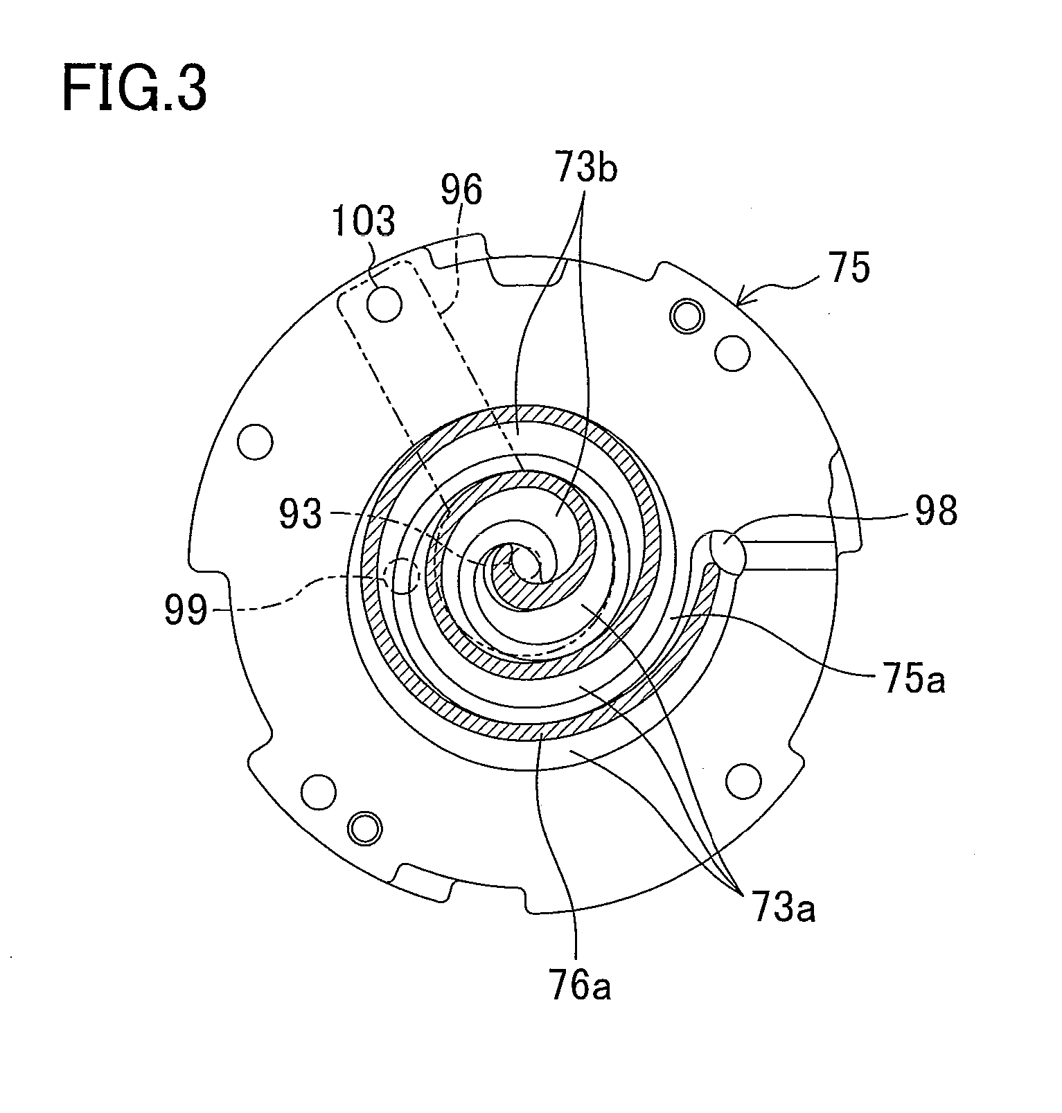
[0031] FIG. 3 is a transverse cross-sectional view illustrating a fixed scroll of the compressor of the first embodiment.
[0032] FIG. 4 is a refrigerant circuit diagram of a refrigeration system according to a second embodiment of the present invention.
DESCRIPTION OF REFERENCE CHARACTERS
[0033] 1 refrigeration system [0034] 4 refrigerant circuit [0035] 14a first compressor [0036] 14b second compressor [0037] 30 injection passageway [0038] 32 oil return passageway [0039] 37 oil separator [0040] 40 compressor mechanism [0041] 42 branch injection pipe (branch injection passageway) [0042] 47 pre-junction pipe (pre-junction passageway) [0043] 48 junction pipe (junction passageway) [0044] 56 discharge pipe
DESCRIPTION OF EMBODIMENTS
[0045] Embodiments of the present invention will be described hereinafter with reference to the drawings.
First Embodiment
[0046] A first embodiment of the present invention will be described. The first embodiment is directed to a refrigeration system (1) according to the present invention. The refrigeration system (1) is a so-called separate-type refrigeration system (1) in which two internal units (60) are connected to one external unit (10), and is configured to cool the inside of a refrigerator.
[0047] The external unit (10) includes an external circuit (11). Each of the internal units (60) includes an internal circuit (61). In the refrigeration system (1), the internal circuits (61) are connected in parallel to the external circuit (11) through a liquid connection pipe (2) and a gas connection pipe (3), thereby forming a refrigerant circuit (4) which performs a vapor compression refrigeration cycle.
[0048] A first shut-off valve (12) and a second shut-off valve (13) are provided at respective ends of the external circuit (11). The first shut-off valve (12) is connected to one end of the liquid connection pipe (2). The other end of the liquid connection pipe (2) is divided into two parts respectively connected to liquid ends of the internal circuits (61). The second shut-off valve (13) is connected to one end of the gas connection pipe (3). The other end of the gas connection pipe (3) is divided into two parts respectively connected to gas ends of the internal circuits (61).
<<External Unit>>
[0049] The external circuit (11) of the external unit (10) includes a compressor mechanism (40), an external heat exchanger (15), a receiver (16), a cooling heat exchanger (17), a first external expansion valve (18), a second external expansion valve (19), and a four-way selector valve (20).
[0050] The compressor mechanism (40) includes a first compressor (14a) having a variable operation capacity, a second compressor (14b) having a fixed operation capacity, and a third compressor (14c) having a fixed operation capacity. These compressors (14a, 14b, 14c) are connected in parallel.
[0051] Each of the first compressor (14a), the second compressor (14b), and the third compressor (14c) is a high-pressure domed hermetic scroll compressor. Power is supplied to the first compressor (14a) through an inverter. The operation capacity of the first compressor (14a) can be adjusted stepwise by changing the output frequency of the inverter. On the other hand, each of the second compressor (14b) and the third compressor (14c) is operated by driving an electric motor at a constant rotation speed, and the operation capacities of the second compressor (14b) and the third compressor (14c) cannot be changed. The configuration of the compressors (14) will be specifically described later.
[0052] In the compressor mechanism (40), only the first compressor (14a) is started at a startup (i.e., at a start of operation) of the compressor mechanism (40). In the compressor mechanism (40) after the startup, as the necessary operation capacity increases, the second compressor (14b) and the third compressor (14c) are started in this order. On the other hand, as the necessary operation capacity decreases, the third compressor (14c) and the second compressor (14b) are stopped in this order. In the compressor mechanism (40), the first compressor (14a) is continuously operated from the startup to the stop of the compressor mechanism (40). During this period, the second compressor (14b) and the third compressor (14c) are turned on/off according to the necessary operation capacity.
[0053] A first discharge pipe (56a) of the first compressor (14a), a second discharge pipe (56b) of the second compressor (14b), and a third discharge pipe (56c) of the third compressor (14c) are connected to one discharge junction pipe (21). On each of the discharge pipes (56), an oil separator (37), a high-pressure pressure switch (39), a check valve (CV1, CV2, CV3) are provided in this order from the side close to the compressor (14).
[0054] Each of the check valves (CV1, CV2, CV3) is configured to stop a flow of a refrigerant toward the compressor (14). The high-pressure pressure switch (39) is configured to urgently stop the compressor (14). The oil separator (37) is in the shape of a hermetic container, and is configured to separate refrigerating machine oil from a refrigerant discharged from the compressor (14). The oil separator (37) constitutes an oil separation mechanism (38) configured to separate refrigerating machine oil from a refrigerant discharged from the compressor mechanism (40). In the first embodiment, the oil separator (37) is provided on each discharge pipe (56). In this configuration, the size of the oil separator (37) can be reduced, as compared to a configuration in which one oil separator is provided on the discharge junction pipe (21).
[0055] In the first embodiment, an oil return passageway (32) is provided in order to return refrigerating machine oil separated by the oil separators (37) to the compressors (14). The oil return passageway (32) is connected to the bottoms (specifically, the bottom surfaces) of the oil separators (37). The oil return passageway (32) temporally combines streams of refrigerating machine oil separated by the oil separators (37), and then distributes the resultant refrigerating machine oil to the compressors (14). Specifically, the oil return passageway (32) includes three pre-junction pipes (47) and one junction pipe (48). The three pre-junction pipes (47) are made of a first pre-junction pipe (47a), a second pre-junction pipe (47b), and a third pre-junction pipe (47c). Each of the pre-junction pipes (47) constitutes a pre-junction passageway (47). The junction pipe (48) constitutes a junction passageway (48).
[0056] An end of the first pre-junction pipe (47a) is connected to a first oil separator (37a) on the first discharge pipe (56a). An end of the second pre-junction pipe (47b) is connected to a second oil separator (37b) on the second discharge pipe (56b). An end of the third pre-junction pipe (47c) is connected to a third oil separator (37c) on the third discharge pipe (56c). The other end of the first pre-junction pipe (47a) and the other end of the second pre-junction pipe (47b) are joined together at an end of the junction pipe (48). The other end of the third pre-junction pipe (47c) is connected to the second pre-junction pipe (47b).
[0057] The other end of the junction pipe (48) is connected to a connection injection tube (33) of an injection passageway (30), which will be described later. The oil return passageway (32) of this embodiment is configured to allow combined refrigerating machine oil from the oil separators (37) to be distributed to the compressors (14) by connecting the junction passageway (48) to a portion of the injection passageway (30) located upstream of a branch point of the injection passageway (30) to the compressors (14). The junction pipe (48) communicates with compression chambers (73) having intermediate pressures of the compressors (14) through the injection passageway (30).
[0058] The first pre-junction pipe (47a) includes a capillary tube (41a) for reducing the pressure of a high-pressure refrigerant to the intermediate pressure. On the second pre-junction pipe (47b) and the third pre-junction pipe (47c), check valves (CV4, CV5) for stopping flows of refrigerants to the oil separators (37b, 37c) and capillary tubes (41b, 41c) for reducing the pressures of high-pressure refrigerants to the intermediate pressures are provided in this order from the side close to the oil separators (37).
[0059] In this embodiment, the check valves (CV4, CV5) are provided only on the pre-junction pipes (47b, 47c) connected to the second compressor (14b) and the third compressor (14c) which are turned on/off during a period from the startup to the stop of the compressor mechanism (40). The check valve (CV4) prevents refrigerating machine oil from flowing from the discharge side into the second compressor (14b) through the second oil separator (37b) when the internal pressure of the second compressor (14b) decreases while the first compressor (14a) operates and the second compressor (14b) does not operate. The check valve (CV5) prevents refrigerating machine oil from flowing from the discharge side into the third compressor (14c) through the third oil separator (37c) when the internal pressure of the third compressor (14c) decreases while the first compressor (14a) operates and the third compressor (14c) does not operate.
[0060] A first suction pipe (57a) is connected to the suction side of the first compressor (14a). A second suction pipe (57b) is connected to the suction side of the second compressor (14b). A third suction pipe (57c) is connected to the suction side of the third compressor (14c). The inlet ends of these suction pipes (57a, 57b, 57c) are connected to the four-way selector valve (20) through a suction junction pipe (22).
[0061] The external heat exchanger (15) is a cross-fin type fin-and-tube heat exchanger. An external fan (23) for sending external air to the external heat exchanger (15) is provided near the external heat exchanger (15). The external heat exchanger (15) performs heat exchange between a refrigerant and external air.
[0062] A gas side of the external heat exchanger (15) is connected to the four-way selector valve (20). A liquid side of the external heat exchanger (15) is connected to the top of the receiver (16) through the first liquid pipe (24). The first liquid pipe (24) includes a check valve (CV8) for stopping a flow of a refrigerant toward the external heat exchanger (15). On the first liquid pipe (24), a capillary tube (51) is provided in parallel with the check valve (CV8).
[0063] The cooling heat exchanger (17) includes a high-pressure side channel (17a) and a low-pressure side channel (17b), and performs heat exchange between refrigerants respectively flowing in the channels (17a, 17b). The cooling heat exchanger (17) is a plate heat exchanger, for example. The cooling heat exchanger (17) may be other types of heat exchangers such as a dual-tube heat exchanger.
[0064] An inflow end of the high-pressure side channel (17a) is connected to the bottom of the receiver (16) through a refrigerant pipe. An outflow end of the high-pressure side channel (17a) is connected to the first shut-off valve (12) through a second liquid pipe (25). The second liquid pipe (25) has a check valve (CV9) for stopping a flow of a refrigerant toward the high-pressure side channel (17a).
[0065] On the other hand, an inflow end of the low-pressure side channel (17b) is connected to a first branch pipe (26) branching off from a portion of the second liquid pipe (25) between the cooling heat exchanger (17) and the check valve (CV9). The first branch pipe (26) has the second external expansion valve (19). The second external expansion valve (19) is an electronic expansion valve having an adjustable opening degree. An outflow end of the low-pressure side channel (17b) is connected to an end of the connection injection tube (33).
[0066] The other end of the connection injection tube (33) is divided into a first branch injection pipe (42a) constituting a first branch injection passageway (42a), a second branch injection pipe (42b) constituting a second branch injection passageway (42b), and a third branch injection pipe (42c) constituting a third branch injection passageway (42c). The first branch injection pipe (42a) is connected to the compression chamber (73) having an intermediate pressure of the first compressor (14a). The second branch injection pipe (42b) is connected to the compression chamber (73) having an intermediate pressure of the second compressor (14b). The third branch injection pipe (42c) is connected to the compression chamber (73) having an intermediate pressure of the third compressor (14c). The connection injection tube (33) is connected to an outlet end of the junction pipe (48). The connection injection tube (33), the first branch injection pipe (42a), the second branch injection pipe (42b), and the third branch injection pipe (42c) constitute the injection passageway (30) for injecting a refrigerant into the compression chambers (73) having intermediate pressures of the compressors (14).
[0067] On the second branch injection pipe (42b) and the third branch injection pipe (42c), solenoid valves (SV1, SV2) which are freely opened and closed and check valves (CV6, CV7) for stopping flows of refrigerants toward the cooling heat exchanger (17) are provided in this order from the side close to the connection injection tube (33). In this embodiment, the solenoid valves (SV1, SV2) and the check valves (CV6, CV7) are provided only on the branch injection pipes (42b, 42c) connected to the second compressor (14b) and the third compressor (14c) which are turned on/off from the startup to the stop of the compressor mechanism (40).
[0068] The solenoid valve (SV1) is open during operation of the second compressor (14b), and is closed during nonoperation of the second compressor (14b). In the same manner, the solenoid valve (SV2) is open during operation of the third compressor (14c), and is closed during nonoperation of the third compressor (14c). Accordingly, refrigerating machine oil in the oil return passageway (32) does not return to the nonoperating compressor (14), but returns to only the operating compressor (14). Each of the solenoid valves (SV1, SV2) constitutes an oil non-return valve.
[0069] The solenoid valves (SV1, SV2) are pilot-operated solenoid valves. Accordingly, even in the closed state of the solenoid valves (SV1, SV2), leakage of refrigerants from the compressors (14b, 14c) occurs. In the first embodiment, in order to prevent such refrigerant leakage, the check valves (CV6, CV7) are provided in addition to the solenoid valves (SV1, SV2).
[0070] The receiver (16) is located between the external heat exchanger (15) and the cooling heat exchanger (17), and can temporarily store a high-pressure refrigerant condensed in the external heat exchanger (15). The gas vent pipe (44) connected to the connection injection tube (33) is connected to the top of the receiver (16). The gas vent pipe (44) has a solenoid valve (SV3) which is freely opened and closed.
[0071] A second branch pipe (28) branches off from a portion of the second liquid pipe (25) between the check valve (CV9) and the first shut-off valve (12). An end of the second branch pipe (28) opposite an end thereof connected to the second liquid pipe (25) is connected to a portion of the first liquid pipe (24) between the check valve (CV8) and the receiver (16). The second branch pipe (28) has a check valve (CV10) for stopping a flow of a refrigerant from the receiver (16).
[0072] A third branch pipe (29) branches off from a portion of the second liquid pipe (25) between the cooling heat exchanger (17) and the check valve (CV9). An end of the third branch pipe (29) opposite an end thereof connected to the second liquid pipe (25) is connected to a portion of the first liquid pipe (24) between the external heat exchanger (15) and the check valve (CV8). A refrigerant flowing in the third branch pipe (29) bypasses the receiver (16) and the cooling heat exchanger (17). The third branch pipe (29) has a first external expansion valve (18) made of an electronic expansion valve having an adjustable opening degree.
[0073] The four-way selector valve (20) has a first port (P1) connected to the discharge junction pipe (21), a second port (P2) connected to the suction junction pipe (22), a third port (P3) connected to the external heat exchanger (15), and a fourth port (P4) connected to the second shut-off valve (13). This four-way selector valve (20) can be switched between a first state (indicated by solid lines in FIG. 1) in which the first port (P1) communicates with the third port (P3) and the second port (P2) communicates with the fourth port (P4) and a second state (indicated by broken lines in FIG. 1) in which the first port (P1) communicates with the fourth port (P4) and the second port (P2) communicates with the third port (P3).
[0074] The external unit (10) includes various types of sensors. Specifically, the discharge junction pipe (21) includes a discharge pressure sensor (43). The discharge pipes (56) are provided with discharge temperature sensors (34a, 34b, 34c). The first suction pipe (57a) includes a suction pressure sensor (36). The suction junction pipe (22) includes a suction temperature sensor (58). The second liquid pipe (25) includes a liquid temperature sensor (45). An external temperature sensor (46) is provided near the external fan (23).
<<Internal Unit>>
[0075] The two internal units (60) have the same configuration. In each of the internal circuits (61) of the internal units (60), a drain-pan heating pipe (62), an internal expansion valve (63), and an internal heat exchanger (64) are provided in this order from the liquid end to the gas end of the internal circuit (61).
[0076] The internal expansion valve (63) is made of an electronic expansion valve having an adjustable opening degree. The internal heat exchanger (64) is made of a cross-fin type fin-and-tube heat exchanger. An internal fan (65) for sending internal air to the internal heat exchanger (64) is provided near the internal heat exchanger (64). The internal heat exchanger (64) performs heat exchange between internal air and a refrigerant.
[0077] A drain pan (66) including a drain-pan heating pipe (62) is provided below the internal heat exchanger (64). The drain pan (66) is used for collecting frost or dew condensation water dropping from the surface of the internal heat exchanger (64). In the drain pan (66), ice blocks generated by freezing of the collected frost or dew condensation water are melted by utilizing heat of a refrigerant flowing in the drain-pan heating pipe (62).
[0078] Each of the internal units (60) has three temperature sensors. Specifically, an evaporation temperature sensor (67) is provided on the heat exchanger tube of the internal heat exchanger (64). A gas temperature sensor (68) is provided near the gas end of the internal circuit (61). An internal temperature sensor (69) is provided near the internal fan (65).
<Configuration of Compressor>
[0079] Configurations of the compressors (14a, 14b, 14c) will be described hereinafter with reference to FIGS. 2 and 3. The compressors (14a, 14b, 14c) have the same configuration, and thus, only the configuration of the first compressor (14a) will be described below.
[0080] The first compressor (14a) includes a casing (70) in the shape of a vertically oriented hermetic container. In the casing (70), an electric motor (85) and a fluid machine (82) are disposed such that the electric motor (85) is located below the fluid machine (82). The electric motor (85) includes a stator (83) fixed to the body of the casing (70), and a rotor (84) located inside the stator (83). A crank shaft (90) is coupled to the rotor (84).
[0081] The fluid machine (82) includes a movable scroll (76) and a fixed scroll (75). The movable scroll (76) includes a substantially disc-shaped movable-side head (76b) and a spiral movable-side lap (76a). A cylindrical projection (76c) into which an eccentric portion of the crank shaft (90) is inserted, is formed so as to stand on the back surface (i.e., the lower surface) of the movable-side head (76b). The movable scroll (76) is supported by a housing (77) located below the movable scroll (76) with an Oldham ring (79) sandwiched therebetween. On the other hand, the fixed scroll (75) includes a substantially disc-shaped fixed-side head (75b) and a spiral fixed-side lap (75a). In the fluid machine (82), the fixed-side lap (75a) engages with the movable-side lap (76a), thereby forming a plurality of compression chambers (73) between these laps (75a, 76a).
[0082] Each of the compressors (14) of the first embodiment employs a so-called asymmetric spiral structure, and the number of turns (i.e., the length of the spiral) of the fixed-side lap (75a) differs from that of the movable-side lap (76a). The compression chambers (73) include: a first compression chamber (73a) located between the inner peripheral surface of the fixed-side lap (75a) and the outer peripheral surface of the movable-side lap (76a); and a second compression chamber (73b) located between the outer peripheral surface of the fixed-side lap (75a) and the inner peripheral surface of the movable-side lap (76a).
[0083] The fluid machine (82) has a suction port (98) formed in an outer edge portion of the fixed scroll (75). The suction port (98) is connected to the first suction pipe (57a). The suction port (98) intermittently communicates with one of the first compression chamber (73a) and the second compression chamber (73b), according to revolution of the movable scroll (76). The suction port (98) has a suction check valve (not shown) for stopping a flow of a refrigerant returning to the first suction pipe (57a) from the compression chambers (73).
[0084] The fluid machine (82) also has a discharge port (93) formed in a center portion of the fixed-side head (75b). The discharge port (93) intermittently communicates with one of the first compression chamber (73a) and the second compression chamber (73b), according to revolution of the movable scroll (76). The discharge port (93) is open to a muffler space (96) located above the fixed scroll (75).
[0085] In the fixed-side head (75b) of the fluid machine (82), an intermediate-pressure port (99) connected to the first branch injection pipe (42a) is formed. The intermediate-pressure port (99) is formed to extend across the fixed-side lap (75a) near a portion between the center of the fixed-side head (75b) and the external periphery. The intermediate-pressure port (99) communicates with both of the first compression chamber (73a) with an intermediate pressure and the second compression chamber (73b) with an intermediate pressure.
[0086] The casing (70) is divided by the disc-shaped housing (77) into an upper suction space (101) and a lower discharge space (100). The suction space (101) communicates with the suction port (98) through a communication port, which is not shown. The discharge space (100) communicates with the muffler space (96) through a communication passageway (103). During operation, a refrigerant discharged from the discharge port (93) flows into the discharge space (100) through the muffler space (96), and thus, the discharge space (100) becomes a high-pressure space which is filled with a refrigerant compressed in the fluid machine (82). The first discharge pipe (56a) is open to the discharge space (100).
[0087] An oil sump for storing refrigerating machine oil is formed at the bottom of the casing (70). A first oil supply passageway (104) which is open to the oil sump is formed in the crank shaft (90). The movable-side head (76b) has a second oil supply passageway (105) connected to the first oil supply passageway (104). In this compressor (14), refrigerating machine oil from the oil sump is supplied to the low-pressure side compression chambers (73) through the first oil supply passageway (104) and the second oil supply passageway (105).
--Operational Behavior--
[0088] Operational behavior of the refrigeration system (1) of the first embodiment will be described below. In cooling operation of the refrigeration system (1), a least the first compressor (14a) of the three compressors (14a, 14b, 14c) is operated so that the interior (i.e., the inside of, for example, a refrigerator) is cooled by the internal units (60).
<Cooling Operation>
[0089] In cooling operation, the four-way selector valve (20) is set in the first state, and the first external expansion valve (18) is fully closed. When the compressor mechanism (40) is operated in this state, a vapor compression refrigeration cycle in which the external heat exchanger (15) serves as a condenser and each of the internal heat exchangers (64) serves as a evaporator, is performed in the refrigerant circuit (4). In this refrigerant circuit (4), a refrigerant flows in the direction indicated by arrows of solid lines in FIG. 1.
[0090] During the cooling operation, superheat degree control of controlling the opening degree of each of the internal expansion valves (63) is performed such that the difference between the value detected by each of the gas temperature sensors (68) and the value detected by each of the evaporation temperature sensors (67) is constant. The opening degree of the second external expansion valve (19) is controlled such that the value detected by the liquid temperature sensor (45) is constant.
[0091] Specifically, when operation of the compressor mechanism (40) is started, refrigerating machine oil is separated in the oil separators (37) from a refrigerant discharged from the compressor mechanism (40), and the resultant refrigerant flows into the external heat exchanger (15). In the external heat exchanger (15), the refrigerant exchanges heat with external air to be condensed. The refrigerant condensed in the external heat exchanger (15) passes through the receiver (16), and then through the high-pressure side channel (17a) of the cooling heat exchanger (17), and flows into the second liquid pipe (25). In the second liquid pipe (25), part of the refrigerant flows into the first branch pipe (26). The other part of the refrigerant flows into the liquid connection pipe (2).
[0092] The refrigerant which has flown into the first branch pipe (26) is subjected to pressure reduction in the second external expansion valve (19), and then flows through the low-pressure side channel (17b) of the cooling heat exchanger (17). In the cooling heat exchanger (17), an intermediate-pressure refrigerant in the low-pressure side channel (17b) is heated by a high-pressure refrigerant in the high-pressure side channel (17a). On the other hand, the refrigerant in the high-pressure side channel (17a) is cooled by the intermediate-pressure refrigerant in the low-pressure side channel (17b) to be in a subcooling state. The refrigerant heated in the low-pressure side channel (17b) is combined with the refrigerating machine oil in the oil return passageway (32), and is distributed to the branch injection pipes (42) to be injected into the compression chambers (73) with the intermediate pressures of the compressors (14). In the first embodiment, mixture of the refrigerant flowing into the compression chambers (73) under the intermediate pressures of the compressors (14) with an oil drop can reduce noise caused by the flow of the refrigerant.
[0093] On the other hand, the refrigerant which has flown into the liquid connection pipe (2) is distributed to the internal circuits (61), is subjected to pressure reduction in the internal expansion valves (63), and then flows into the internal heat exchangers (64). In each of the internal heat exchangers (64), the refrigerant exchanges heat with internal air, and evaporates. The internal air is cooled by the refrigerant. The refrigerants which have evaporated in the internal heat exchangers (64) are combined together in the gas connection pipe (3), and then are sucked into the suction sides of the compressors (14).
<Defrosting Operation>
[0094] In this refrigeration system (1), when the amount of frost attached to the internal heat exchangers (64) during cooling operation increases, defrosting operation is performed in order to remove the frost. In the defrosting operation, defrosting processes of the respective internal heat exchangers (64) are performed at the same time.
[0095] In the defrosting operation, the four-way selector valve (20) is set in the second state, and each of the internal expansion valves (63) is fully opened. When the compressor mechanism (40) is operated in this state, a vapor compression refrigeration cycle in which the external heat exchanger (15) serves as an evaporator and each of the internal heat exchangers (64) serves as a condenser, is performed in the refrigerant circuit (4). In this refrigerant circuit (4), a refrigerant flows in the direction indicated by arrows of broken lines in FIG. 1. In the defrosting operation, the opening degrees of the first external expansion valve (18) and the second external expansion valve (19) are adjusted as necessary.
[0096] Specifically, when operation of the compressor mechanism (40) is started, refrigerating machine oil is separated in the oil separators (37) from a refrigerant discharged from the compressor mechanism (40), and then the resultant refrigerant is distributed to the internal heat exchangers (64). In each of the internal heat exchangers (64), frost attached to the internal heat exchanger (64) is melted by a high-pressure refrigerant, and the refrigerant is cooled by the frost to be condensed. The refrigerants condensed in the respective internal heat exchangers (64) are combined together in the liquid connection pipe (2), and the resultant refrigerant passes through the receiver (16), and then flows into the third branch pipe (29) through the high-pressure side channel (17a) of the cooling heat exchanger (17). The refrigerant which has flown into the third branch pipe (29) is subjected to pressure reduction in the first external expansion valve (18), and then flows into the external heat exchanger (15). In the external heat exchanger (15), the refrigerant exchanges heat with external air, and evaporates. The refrigerant which has evaporated in the external heat exchanger (15) is sucked into the suction sides of the compressors (14).
[0097] In the first embodiment, in the cooling operation and the defrosting operation, refrigerating machine oil discharged together with refrigerants from the compressors (14), flows into the oil separators (37), and is separated from the refrigerants in the oil separators (37). The refrigerating machine oil separated in one of the oil separators (37) flows into the junction pipe (48) through the pre-junction pipes (47), and is combined together with refrigerating machine oil separated in the other oil separators (37). The refrigerating machine oil streams combined in the junction pipe (48) are combined with a refrigerant in the injection passageway (30), and the resultant refrigerating machine oil is distributed to the compressors (14) at a branch point of the injection passageway (30). The refrigerating machine oil distributed to the compressors (14) flows into the compression chambers (73) with intermediate pressures of the respective compressors (14).
[0098] In the first embodiment, refrigerating machine oil streams separated in the oil separators (37) are combined together in the oil return passageway (32), and then the resultant refrigerating machine oil is distributed to the compressors (14). In each of the compressors (14), as the oil surface in the oil sump becomes higher, the oil mixture rate increases, i.e., the amount of refrigerating machine oil contained in a discharged refrigerant per a unit flow rate increases. Accordingly, when refrigerating machine oil begins to flow mainly into, for example, the first compressor (14a), the flow rate of refrigerating machine oil discharged from the first compressor (14a) increases, and the flow rate of refrigerating machine oil discharged from the second and third compressors (14b, 14c) decreases. On the other hand, the flow rate of refrigerating machine oil returning to the compressors (14) changes according to the total flow rate of refrigerating machine oil discharged from the compressors (14). Thus, even when the flow rate of refrigerating machine oil discharged from the first compressor (14a) increases, the flow rate of the refrigerating machine oil returning to the first compressor (14a) does not increase accordingly. Likewise, even when the flow rate of refrigerating machine oil discharged from the second and third compressors (14b, 14c) decreases, the flow rate of refrigerating machine oil returning to the second and third compressors (14b, 14c) does not decrease accordingly. Therefore, when refrigerating machine oil begins to flow mainly into the first compressor (14a), the amount of refrigerating machine oil in the first compressor (14a) decreases, and the amount of refrigerating machine oil in the second and third compressors (14b, 14c) increases. In this manner, in this embodiment, when an oil imbalance begins to occur in the compressor mechanism (40), progress of this oil imbalance is automatically reduced.
[0099] In the first embodiment, as the operation capacity of the first compressor (14a) increases, a larger amount of refrigerating machine oil is discharged from the first compressor (14a). On the other hand, as the operation capacity of the first compressor (14a) increases, the flow rate of refrigerating machine oil to be distributed to the first compressor (14a) increases. Accordingly, in the first compressor (14a), even when the operation capacity changes to change the flow rate of discharged refrigerating machine oil, the amount of refrigerating machine oil in the oil sump does not greatly change. Thus, in the second and third compressors (14b, 14c), the amount of refrigerating machine oil in the oil sump does not greatly change, either.
[0100] In the first embodiment, the second compressor (14b) is switched from an operating state to a nonoperation state while the first compressor (14a) operates in some cases. In such cases, when the second compressor (14b) is stopped, the movable scroll (76) pushed against the fixed scroll (75) during operation falls in the second compressor (14b), and a refrigerant in the discharge space (100) flows into the suction check valve, so that the pressure in the fluid machine (82) becomes high. If the second compressor (14b) is started again with the pressure in the fluid machine (82) being high, the fluid machine (82) compresses the high-pressure refrigerant, resulting in that the discharge pressure of the fluid machine (82) excessively increases to damage the fluid machine (82) in some cases. In the first embodiment, to prevent the second compressor (14b) from being damaged at the restart of the second compressor (14b), the check valve (CV2) constituting a refrigerant-inflow stop valve is provided and the discharge side of the second compressor (14b) communicates with the compression chamber (73) with the intermediate pressure of the first compressor (14a) through the second pre-junction pipe (47b), the junction pipe (48), and the first branch injection pipe (42a). With this configuration, a flow of the refrigerant discharged from the first compressor (14a) into the nonoperating second compressor (14b) is stopped, and in addition, a refrigerant in the discharge space (100) in the second compressor (14b) is sucked by the first compressor (14a). Accordingly, the pressure of the discharge space (100) in the second compressor (14b) and the pressure in the fluid machine (82) gradually decrease immediately after the second compressor (14b) is stopped. In the same manner, in the case where the third compressor (14c) is stopped, the pressure of the discharge space (100) in the third compressor (14c) and the pressure in the fluid machine (82) gradually decrease.
Advantages of First Embodiment
[0101] In the first embodiment, the oil return passageway (32) is configured so as to combine refrigerating machine oil streams respectively separated in the oil separators (37), and then distribute the resultant refrigerating machine oil to the compressors (14). With this configuration, even when an oil imbalance in which refrigerating machine oil flows mainly into a specific one of the compressors (14) occurs in the compressor mechanism (40), progress of the oil imbalance is automatically reduced. Accordingly, a significant imbalance of refrigerating machine oil in a specific compressor (14) hardly occurs, and each of the compressors (14) is hardly in short of refrigerating machine oil. As a result, lubrication failures due to a shortage of refrigerating machine oil in one of the compressors (14) can be reduced.
[0102] In the first embodiment, refrigerating machine oil combined in the oil return passageway (32) is distributed to the compressors (14) at a branch point of the injection passageway (30). That is, no branch point is provided on the oil return passageway (32), but the branch point of the injection passageway (30) is used to distribute the combined refrigerating machine oil to the compressors (14). Accordingly, a configuration in which refrigerating machine oil streams separated in the oil separators (37) are combined together and the resultant refrigerating machine oil is distributed to the compressors (14), can be simplified.
[0103] In the first embodiment, refrigerating machine oil in the oil return passageway (32) does not return to nonoperating ones of the compressors (14) and returns only to an operating one of the compressors (14). This configuration can reduce accumulation of the refrigerating machine oil in the nonoperating compressors (14). Accordingly, as compared to a configuration in which the oil non-return valve (SV1) is not provided, a large amount of refrigerating machine oil can return to an operating one of the compressors (14) which needs refrigerating machine oil. As a result, a shortage of refrigerating machine oil in the operating compressor (14) can be reduced.
[0104] In the first embodiment, the check valve (CV4) is provided in the second pre-junction pipe (47b) such that a flow of refrigerating machine oil from the discharge side into the nonoperating second compressor (14b) is stopped. Accordingly, as compared to a configuration in which the check valve (CV4) is not provided in the second pre-junction pipe (47b), a large amount of refrigerating machine oil can return to the operating first compressor (14a) which needs refrigerating machine oil. As a result, a shortage of refrigerating machine oil in the first compressor (14a) can be reduced. The same advantages can also be obtained by providing the check valve (CV5) on the third pre-junction pipe (47c).
[0105] In the first embodiment, in the case where the second compressor (14b) is stopped while the first compressor (14a) operates, the check valve (CV2) stops a flow of a high-pressure refrigerant into the second compressor (14b), and a refrigerant in the discharge space (100) in the second compressor (14b) is sucked by the first compressor (14a). With this configuration, the pressure of the discharge space (100) in the second compressor (14b) is forcedly reduced. This decrease in the pressure of the discharge space (100) causes the pressure in the fluid machine (82) of the second compressor (14b) to also decrease. Consequently, it is possible to prevent the fluid machine (82) of the second compressor (14b) from compressing a high-pressure refrigerant at a restart of the second compressor (14b), thereby reducing damage on the second compressor (14b) at the restart. The same advantages can also be obtained by providing the check valve (CV3) in the third discharge pipe (56c).
[0106] In the first embodiment, refrigerating machine oil separated in the oil separators (37) is returned to the compression chambers (73) with the intermediate pressures of the compressors (14). Thus, the flow rates of low-pressure refrigerants to be sucked by the compressors (14) do not change depending on the returned refrigerating machine oil. Accordingly, refrigerating machine oil can return to the compressors (14) without degradation of operating capability of the refrigeration system.
[0107] In the first embodiment, as the amount of refrigerating machine oil discharged from the first compressor (14a) with a variable operation capacity increases, a larger amount of refrigerating machine oil returns to the first compressor (14a). That is, even when the operation capacity of the first compressor (14a) varies to change the flow rate of discharged refrigerating machine oil, the amount of refrigerating machine oil in the first compressor (14a) does not greatly change. Accordingly, in the case of using a compressor (14) with a variable operation capacity in which the flow rate of refrigerating machine oil changes depending on the operation capacity, an oil imbalance in the compressor mechanism (40) can be reduced.
Second Embodiment
[0108] A second embodiment of the present invention will be described. In the following description, aspects different from those in the first embodiment are described.
[0109] As illustrated in FIG. 4, a refrigeration system (1) according to the second embodiment includes an air conditioning unit (50) configured to perform air conditioning of interior space, and an internal units (60) including a cold storage unit (60a) and a refrigeration unit (60b). A refrigerant circuit (4) includes an air conditioning section (71) provided with the air conditioning unit (50) and a cooling section (72) provided with the cold storage unit (60a) and the refrigeration unit (60b). The air conditioning section (71) and the cooling section (72) share a liquid connection pipe (2). In the cooling section (72), a booster unit (80) is serially connected to the refrigeration unit (60b).
<<External Unit>>
[0110] A discharge side of a compressor mechanism (40) is provided with a second four-way selector valve (111). The second four-way selector valve (111) has a first port (P1) connected to a discharge branch pipe (97) branching off from a discharge junction pipe (21), a second port (P2) connected to a third suction pipe (57c), and a fourth port (P4) connected to a second port (P2) of a first four-way selector valve (20). A third port (P3) of the second four-way selector valve (111) is configured as a shut-off port which is closed.
[0111] On the other hand, a suction side of the compressor mechanism (40) is provided with a third four-way selector valve (112). The third four-way selector valve (112) has a first port (P1) connected to a second high-pressure pipe (121), which will be described later, a second port (P2) connected to a second suction pipe (57b), a third port (P3) connected to a second suction branch pipe (31b) branching off from a third suction pipe (57c), and a fourth port (P4) connected to a first suction branch pipe (31a) branching off from a first suction pipe (57a). The first suction branch pipe (31a) and the second suction branch pipe (31b) respectively have check valves (CV11, CV12) which allow only flows of refrigerants toward the third four-way selector valve (112). The first suction pipe (57a) is connected to a third shut-off valve (113).
[0112] Each of the first through third four-way selector valves (20, 111, 112) can be switched between a first state (indicated by solid lines in FIG. 1) in which the first port (P1) communicates with the third port (P3) and the second port (P2) communicates with the fourth port (P4) and a second state (indicated by broken lines in FIG. 1) in which the first port (P1) communicates with the fourth port (P4) and the second port (P2) communicates with the third port (P3).
[0113] A check valve (CV13) for stopping a flow of a refrigerant toward a first oil separator (37a) is provided at a position of a first pre-junction pipe (47a) upstream of a capillary tube (41a). On a first branch injection pipe (42a), a solenoid valve (SV4) which is freely opened and closed and a check valve (CV14) for stopping a flow of a refrigerant toward a connection injection tube (33) are provided in this order from the side close to the connection injection tube (33).
[0114] As the solenoid valves (SV1, SV2) are, the solenoid valve (SV4) is open during operation of a first compressor (14a), and is closed during nonoperation of the first compressor (14a). The solenoid valve (SV4) is a pilot-operated solenoid valve. Even in the closed state of the solenoid valve (SV4), a refrigerant leaks from a portion near the first compressor (14a). Accordingly, the check valve (CV14) is provided in order to prevent a back-flow of a refrigerant in the first branch injection pipe (42a).
[0115] A second branch pipe (28) branches off from a first branch pipe (26). The second branch pipe (28) has a third external expansion valve (110) made of an electronic expansion valve having an adjustable opening degree. On the second branch pipe (28), a solenoid valve (SV5) which is freely opened and closed is provided in parallel with the third external expansion valve (110). A first high-pressure pipe (120) connected to the discharge junction pipe (21) branches off from the second branch pipe (28). The first high-pressure pipe (120) has a check valve (CV15) allowing only a flow of a refrigerant toward the discharge junction pipe (21). A second high-pressure pipe (121) connected to the third four-way selector valve (112) branches off from the first high-pressure pipe (120). A third high-pressure tube (122) connected to a first liquid pipe (24) branches off from the second high-pressure pipe (121). The third high-pressure tube (122) has a solenoid valve (SV6) which is freely opened and closed.
<<Air Conditioning Unit>>
[0116] The air conditioning unit (50) houses an air conditioning circuit (52) constituting part of the air conditioning section (71). A gas side of the air conditioning circuit (52) is connected to a third gas connection pipe (3c). A liquid side of the air conditioning circuit (52) is connected to a third liquid connection pipe (2c) branching off from the liquid connection pipe (2).
[0117] In the air conditioning circuit (52), an indoor expansion valve (53) made of an electronic expansion valve having an adjustable opening degree and an indoor heat exchanger (54) made of a cross-fin type fin-and-tube heat exchanger are provided in this order from the liquid end to the gas end. An indoor fan (55) for sending indoor air to the indoor heat exchanger (54) is provided near the indoor heat exchanger (54).
<<Cold Storage Unit, Refrigeration Unit>>
[0118] The cold storage unit (60a) and the refrigeration unit (60b) respectively house internal circuits (61a, 61b) constituting part of the cooling section (72). A gas side of the first internal circuit (61a) of the cold storage unit (60a) is connected to a first gas connection pipe (3a). A liquid side of the first internal circuit (61a) is connected to a first liquid connection pipe (2a) branching off from the liquid connection pipe (2). On the other hand, a gas side of the second internal circuit (61b) of the refrigeration unit (60b) is connected to a second gas connection pipe (3b). A liquid side of the second internal circuit (61b) is connected to a second liquid connection pipe (2b) branching off from the liquid connection pipe (2).
[0119] In the internal circuits (61a, 61b), internal expansion valves (63a, 63b) made of electronic expansion valves having adjustable opening degrees and internal heat exchangers (64a, 64b) made of cross-fin type fin-and-tube heat exchangers are provided in this order from the liquid end to the gas end. Internal fans (65a, 65b) for sending internal air to the internal heat exchangers (64a, 64b) are provided near the internal heat exchangers (64a, 64b).
<<Booster Unit>>
[0120] The booster unit (80) houses a booster circuit (81) constituting part of the cooling section (72). The booster circuit (81) includes a booster compressor (86). On a discharge pipe (78) of the booster compressor (86), an oil separator (87), a high-pressure pressure switch (88), and a check valve (CV16) are provided in this order from the side close to the booster compressor (86). The oil separator (87) is connected to an oil return pipe (92) including a capillary tube (91). The booster circuit (81) includes a bypass pipe (95) for allowing a refrigerant to bypass the booster compressor (86). The bypass pipe (95) has a check valve (CV17).
--Operational Behavior--
[0121] Operational behavior of the refrigeration system (1) will be described hereinafter for each operation. The refrigeration system (1) is configured to select from among eight operation modes. Specifically, the eight operation modes are: <i> air cooling operation of performing only air cooling by the air conditioning unit (50); <ii> air heating operation of performing only air heating by the air conditioning unit (50); <iii> cooling operation of performing only cooling of the interior (i.e., the inside of, for example, a refrigerator) by the cold storage unit (60a) and the refrigeration unit (60b); <iv> first air cooling/cooling operation of performing cooling of the interior by the cold storage unit (60a) and the refrigeration unit (60b) and air cooling by the air conditioning unit (50); <v> second air cooling/cooling operation performed when the air conditioning unit (50) has an insufficient air-cooling capability in the first air cooling/cooling operation; <vi> first air heating/cooling operation of performing cooling of the interior by the cold storage unit (60a) and the refrigeration unit (60b) and air heating by the air conditioning unit (50) without using the external heat exchanger (15); <vii> second air heating/cooling operation performed when the air conditioning unit (50) has a redundant air heating capability in the first air heating/cooling operation; and <viii> third air heating/cooling operation performed when the air conditioning unit (50) has an insufficient air heating capability in the first air heating/cooling operation. In this refrigeration system (1), the opening degree of the second external expansion valve (19) is adjusted as necessary, thereby adjusting the flow rate of a refrigerant to be injected into compression chambers (73) with intermediate pressures of compressors (14).
<Air Cooling Operation>
[0122] In air cooling operation, the third compressor (14c) is operated with the first four-way selector valve (20) and the second four-way selector valve (111) set in the first state. The opening degree of the indoor expansion valve (53) is adjusted as necessary. The first external expansion valve (18) and the internal expansion valves (63) are closed. In the air cooling operation, when the air cooling capability is insufficient, the second compressor (14b) is also operated. In this case, the third four-way selector valve (112) is set in the second state. The first compressor (14a) is always stopped. In the air cooling operation, a vapor compression refrigeration cycle in which the external heat exchanger (15) serves as a condenser and the indoor heat exchanger (54) serves as an evaporator, is performed.
<Air Heating Operation>
[0123] In air heating operation, the third compressor (14c) is operated with the first four-way selector valve (20) set in the second state and the second four-way selector valve (111) set in the first state. The opening degrees of the indoor expansion valve (53) and the first external expansion valve (18) are adjusted as necessary. The internal expansion valves (63) are closed. In the air heating operation, when the air heating capability is insufficient, the second compressor (14b) is also performed. In this case, the third four-way selector valve (112) is set in the second state. The first compressor (14a) is always stopped. In the air heating operation, a vapor compression refrigeration cycle in which the indoor heat exchanger (54) serves as a condenser and the external heat exchanger (15) serves as an evaporator, is performed.
<Cooling Operation>
[0124] In cooling operation, the first compressor (14a) is operated with the first four-way selector valve (20) set in the first state. The opening degrees of the internal expansion valves (63) are adjusted as necessary. The first external expansion valve (18) and the indoor expansion valve (53) are closed. In the cooling operation, when the cooling capability for the interior is insufficient, the second compressor (14b) is also performed. In this case, the third four-way selector valve (112) is set in the first state. The third compressor (14c) is always stopped. In the cooling operation, a vapor compression refrigeration cycle in which the external heat exchanger (15) serves as a condenser and each of the internal heat exchangers (64) serves as an evaporator, is performed.
<First Air Cooling/Cooling Operation>
[0125] In first air cooling/cooling operation, the first compressor (14a) and the third compressor (14c) are operated with the first four-way selector valve (20) and the second four-way selector valve (111) set in the first state. The opening degrees of the internal expansion valves (63) and the indoor expansion valve (53) are adjusted as necessary. The first external expansion valve (18) is closed. In the first air cooling/cooling operation, when the cooling capability for the interior is insufficient, the second compressor (14b) is also operated. In this case, the third four-way selector valve (112) is set in the first state. In the first air cooling/cooling operation, a vapor compression refrigeration cycle in which the external heat exchanger (15) serves as a condenser and each of the indoor heat exchanger (54) and the internal heat exchangers (64) serves as an evaporator, is performed.
<Second Air Cooling/Cooling Operation>
[0126] Second air cooling/cooling operation is performed by switching the third four-way selector valve (112) to the second state when the air cooling capability is insufficient in the first air cooling/cooling operation. In the second air cooling/cooling operation, the second compressor (14b) is switched to the air conditioning section (71). The settings in the second air cooling/cooling operation are basically the same as those in the first air cooling/cooling operation, except for the third four-way selector valve (112).
<First Air Heating/Cooling Operation>
[0127] First air heating/cooling operation is 100% heat recovery operation in which the external heat exchanger (15) is not used and cooling of the interior by the cold storage unit (60a) and the refrigeration unit (60b) and air heating by the air conditioning unit (50) are performed. In the first air heating/cooling operation, the first compressor (14a) is operated with the first four-way selector valve (20) set in the second state and the second four-way selector valve (111) set in the first state. The opening degrees of the internal expansion valves (63) and the indoor expansion valve (53) are adjusted as necessary. The first external expansion valve (18), the second external expansion valve (19), and the third external expansion valve (110) are closed. In the first air heating/cooling operation, when the cooling capability for the interior is insufficient, the second compressor (14b) is also operated. In this case, the third four-way selector valve (112) is set in the first state. In the first air heating/cooling operation, a vapor compression refrigeration cycle in which the indoor heat exchanger (54) serves as a condenser and each of the internal heat exchangers (64) serves as an evaporator, is performed.
<Second Air Heating/Cooling Operation>
[0128] Second air heating/cooling operation is performed by switching the second four-way selector valve (111) to the second state when the air heating capability is redundant in the first air heating/cooling operation. In the second air heating/cooling operation, the external heat exchanger (15) serves as a condenser. The settings in the second air heating/cooling operation are basically the same as those in the first air heating/cooling operation, except for the second four-way selector valve (111).
<Third Air Heating/Cooling Operation>
[0129] Third air heating/cooling operation is performed by operating the third compressor (14c) with the second four-way selector valve (111) set in the first state and the first external expansion valve (18) opened, when the air heating capability is insufficient in the first air heating/cooling operation. In the third air heating/cooling operation, a vapor compression refrigeration cycle in which the indoor heat exchanger (54) serves as a condenser and each of the internal heat exchangers (64) and the external heat exchanger (15) serves as an evaporator, is performed.
Other Embodiments
[0130] The foregoing embodiments may have the following configurations.
[0131] In the foregoing embodiments, the oil return passageway (32) may be configured to allow refrigerating machine oil to return to the suction pipes (57).
[0132] In the foregoing embodiments, the compressors (14) may be compressors with symmetric spiral structures, or compressors except scroll compressors.
[0133] In the foregoing embodiments, the second compressor (14b) and the third compressor (14c) may be compressors having variable operation capacities.
[0134] In the foregoing embodiments, the refrigeration system (1) may be configured to perform a supercritical cycle in which the high pressure of a refrigeration cycle is higher than a critical pressure of a refrigerant. In this case, a heat exchanger serving as a condenser in a normal refrigeration cycle in which the high pressure of a refrigeration cycle is lower than a critical pressure of a refrigerant, serves as a gas cooler.
[0135] The foregoing embodiments are merely preferred examples in nature, and are not intended to limit the scope, applications, and use of the invention.
INDUSTRIAL APPLICABILITY
[0136] As described above, the present invention is useful for a refrigeration system in which a compressor mechanism including a plurality of compressors is provided in a refrigerant circuit.
* * * * *
D00000
D00001
D00002
D00003
D00004
XML
uspto.report is an independent third-party trademark research tool that is not affiliated, endorsed, or sponsored by the United States Patent and Trademark Office (USPTO) or any other governmental organization. The information provided by uspto.report is based on publicly available data at the time of writing and is intended for informational purposes only.
While we strive to provide accurate and up-to-date information, we do not guarantee the accuracy, completeness, reliability, or suitability of the information displayed on this site. The use of this site is at your own risk. Any reliance you place on such information is therefore strictly at your own risk.
All official trademark data, including owner information, should be verified by visiting the official USPTO website at www.uspto.gov. This site is not intended to replace professional legal advice and should not be used as a substitute for consulting with a legal professional who is knowledgeable about trademark law.