Expander-integrated Compressor And Refrigeration Cycle Apparatus Using The Same
Takahashi; Yasufumi ; et al.
U.S. patent application number 12/865085 was filed with the patent office on 2010-12-30 for expander-integrated compressor and refrigeration cycle apparatus using the same. This patent application is currently assigned to PANASONIC CORPORATION. Invention is credited to Hiroshi Hasegawa, Yasufumi Takahashi.
| Application Number | 20100326124 12/865085 |
| Document ID | / |
| Family ID | 40912523 |
| Filed Date | 2010-12-30 |


| United States Patent Application | 20100326124 |
| Kind Code | A1 |
| Takahashi; Yasufumi ; et al. | December 30, 2010 |
EXPANDER-INTEGRATED COMPRESSOR AND REFRIGERATION CYCLE APPARATUS USING THE SAME
Abstract
An expander-integrated compressor (100A) has a compression mechanism (2), an expansion mechanism (3), a shaft (5), an oil pump (6), and an oil supply amount regulating mechanism (30). The compression mechanism (2) and the expansion mechanism (3) are coupled to each other by the shaft (5) so that mechanical power can be transmitted. The compression mechanism (2) and the expansion mechanism (3) are arrayed vertically in the closed casing (1). The oil pump (6) is provided at a lower portion of the shaft (5). An oil supply passage (29) is formed in the shaft (5) so as to extend in the axis direction. The oil supply amount regulating mechanism 30 controls the amount of the oil to be supplied by the oil pump (6) to the expansion mechanism (3).
| Inventors: | Takahashi; Yasufumi; (Osaka, JP) ; Hasegawa; Hiroshi; (Osaka, JP) |
| Correspondence Address: |
    HAMRE, SCHUMANN, MUELLER & LARSON P.C.
    P.O. BOX 2902
    MINNEAPOLIS
    MN
    55402-0902
    US
|
| Assignee: | PANASONIC CORPORATION Kadoma-shi, Osaka JP |
| Family ID: | 40912523 |
| Appl. No.: | 12/865085 |
| Filed: | January 27, 2009 |
| PCT Filed: | January 27, 2009 |
| PCT NO: | PCT/JP2009/000295 |
| 371 Date: | July 28, 2010 |
| Current U.S. Class: | 62/468 ; 62/498 |
| Current CPC Class: | F04C 23/003 20130101; F04C 23/008 20130101; F04C 18/356 20130101; F04C 29/025 20130101; F04C 29/028 20130101 |
| Class at Publication: | 62/468 ; 62/498 |
| International Class: | F25B 43/00 20060101 F25B043/00; F25B 1/00 20060101 F25B001/00 |
Foreign Application Data
| Date | Code | Application Number |
|---|---|---|
| Jan 29, 2008 | JP | 2008-018354 |
Claims
1. An expander-integrated compressor comprising: a rotary-type compression mechanism for compressing a working fluid; a rotary-type expansion mechanism for recovering mechanical power from the working fluid; a shaft coupling the rotary-type compression mechanism and the rotary-type expansion mechanism so as to transmit the mechanical power recovered by the rotary-type expansion mechanism to the rotary-type compression mechanism; a closed casing accommodating the rotary-type compression mechanism, the rotary-type expansion mechanism, and the shaft in such a manner that the rotary-type compression mechanism and the rotary-type expansion mechanism are arrayed vertically, the closed casing having a bottom portion utilized as an oil reservoir and an interior space to be filled with the working fluid having been compressed; an oil pump provided at a lower portion of the shaft; an oil supply passage for supplying oil in the oil reservoir to the rotary-type compression mechanism or the rotary-type expansion mechanism located in an upper part of the closed casing by the oil pump, the oil supply passage being formed in the shaft so as to extend in an axis direction; and an oil supply amount regulating mechanism, disposed below the rotary-type compression mechanism or the rotary-type expansion mechanism located in the upper part of the closed casing and disposed above the rotary-type compression mechanism or the rotary-type expansion mechanism located in a lower part of the closed casing, for regulating the amount of the oil to be supplied through the oil supply passage to the rotary-type compression mechanism or the rotary-type expansion mechanism located in the upper part of the closed casing, and wherein: a branch passage is formed in the shaft, the branch passage branching in a radial direction from the oil supply passage and opening in an outer circumferential surface of the shaft; and the oil supply amount regulating mechanism is provided in the branch passage or exteriorly of the shaft so that the oil is guided to the interior space of the closed casing through the branch passage.
2. The expander-integrated compressor according to claim 1, wherein the oil supplied through the oil supply passage does not flow out over the rotary-type compression mechanism or the rotary-type expansion mechanism located in the upper part of the closed casing.
3. The expander-integrated compressor according to claim 1, wherein the oil supply passage does not open in an upper end face of the shaft.
4. The expander-integrated compressor according to claim 1, wherein the oil supply amount regulating mechanism includes a structure for preventing the amount of the oil to be supplied to the rotary-type compression mechanism or the rotary-type expansion mechanism through the oil supply passage, from increasing correspondingly to an increase of a rotation speed of the shaft.
5. The expander-integrated compressor according to claim 1, wherein the oil supply amount regulating mechanism includes an orifice, a needle valve, or a relief valve.
6. The expander-integrated compressor according to claim 1, further comprising: a motor, disposed between the rotary-type compression mechanism and the rotary-type expansion mechanism, for driving the shaft; and wherein the branch passage is formed in a portion of the shaft that is between the motor and the rotary-type compression mechanism or the rotary-type expansion mechanism located in the lower part of the closed casing.
7. The expander-integrated compressor according to claim 1, wherein: the rotary-type compression mechanism or the rotary-type expansion mechanism includes a bearing portion for supporting the shaft and covering the outer circumferential surface of the shaft at a location where the branch passage is formed; (i) a chamber in which the branch passage opens and (ii) an oil discharge passage for connecting the chamber and the interior space of the closed casing are formed in the bearing portion; and the oil is guided from the oil supply passage to the interior space of the closed casing through the branch passage, the chamber, and the oil discharge passage.
8. The expander-integrated compressor according to claim 1, wherein the oil supply amount regulating mechanism includes a valve seat, a valve body disposed so as to face the valve seat, and a spring for adjusting a gap between the valve seat and the valve body by expanding and contracting according to a pressure change of the oil in the oil supply passage.
9. The expander-integrated compressor according to claim 8, wherein the shape of the valve body is spherical.
10. The expander-integrated compressor according to claim 7, wherein the oil supply amount regulating mechanism is provided in the chamber, in the oil discharge passage, or at an outlet of the oil discharge passage.
11. The expander-integrated compressor according to claim 1, wherein the oil pump is a velocity type pump.
12. A refrigeration cycle apparatus comprising: an expander-integrated compressor according to claim 1; a radiator for cooling the refrigerant compressed by the rotary-type compression mechanism of the expander-integrated compressor; and an evaporator for evaporating the refrigerant expanded by the rotary-type expansion mechanism of the expander-integrated compressor.
13. (canceled)
Description
TECHNICAL FIELD
[0001] The present invention relates to an expander-integrated compressor and a refrigeration cycle apparatus using the same.
BACKGROUND ART
[0002] Recently, as natural resource issues and global warming issues have become ever more serious, much research and development efforts have been invested in reducing energy consumption of refrigeration cycle apparatuses, which are used for water heaters and air conditioners. For example, conventional refrigeration cycle apparatuses have a mechanism of expanding the refrigerant using an expansion valve, but there is an attempt to employ a positive displacement expander in place of the expansion valve in order to recover the energy of expansion of the refrigerant and utilize it as auxiliary power for the compressor. By the recovery and utilization of the expansion energy of the refrigerant, it can be expected to achieve about a 20% reduction in power usage theoretically, or about a 10% reduction even with an actual apparatus. As a fluid machine that achieves such an attempt, development of a fluid machine (expander-integrated compressor), such as disclosed in JP 2005-299632 A, is underway at a rapid pace.
[0003] FIG. 11 is a vertical cross-sectional view illustrating a typical expander-integrated compressor. An expander-integrated compressor 200 has a two-stage rotary type compression mechanism 121, a motor 122, a two-stage rotary type expansion mechanism 123, and a closed casing 120 that accommodates them. The compression mechanism 121, the motor 122, and the expansion mechanism 123 are coupled to each other by a shaft 124.
[0004] A bottom part of the closed casing 120 forms an oil reservoir 125 for holding oil (refrigeration oil). An oil pump 126 is fitted to a lower end portion of the shaft 124 in order to pump up the oil held in the oil reservoir 125. The oil pumped up by the oil pump 126 is supplied to the compression mechanism 121 and the expansion mechanism 123 via an oil supply passage 127 formed in the shaft 124. Thereby, lubricity and sealing of the sliding parts of the compression mechanism 121 and the expansion mechanism 123 are ensured.
[0005] An oil return pipe 128 is disposed in an upper part of the expansion mechanism 123. One end of the oil return pipe 128 communicates with the oil supply passage 127 formed in the shaft 124, while the other end opens below the expansion mechanism 123. Generally, the oil is supplied excessively in order to ensure the reliability of the expansion mechanism 123. The excess oil is returned via the oil return pipe 128 to the oil reservoir 125.
[0006] By disposing both the compression mechanism 121 and the expansion mechanism 123 in the closed casing 120, there is an advantage in being able to lubricate both the compression mechanism 121 and the expansion mechanism 123 by the oil held in the oil reservoir 125.
DISCLOSURE OF THE INVENTION
[0007] In the expander-integrated compressor 200 shown in FIG. 11, the oil pumped up from the oil reservoir 125 is heated by the compression mechanism 121 because it passes through the compression mechanism 121 that is at a high temperature. The oil heated by the compression mechanism 121 is heated further by the motor 122, and it reaches the expansion mechanism 123. The oil having reached the expansion mechanism 123 is cooled by the expansion mechanism 123 that is at a low temperature, and is thereafter discharged below the expansion mechanism 123 via the oil return pipe 128. The oil discharged from the expansion mechanism 123 and the oil return pipe 128 is heated again when passing along a side face of the motor 122 and is also heated when passing along a side face of the compression mechanism 121. The oil then returns to the oil reservoir 125 of the closed casing 120.
[0008] As described above, the oil circulation between the compression mechanism 121 and the expansion mechanism 123 causes heat transfer from the compression mechanism 121 to the expansion mechanism 123. Such heat transfer lowers the temperature of the refrigerant discharged from the compression mechanism 121, and elevates the temperature of the refrigerant discharged from the expansion mechanism 123. In terms of air conditioners, this means a decrease of indoor heating capacity during heating, or a decrease of indoor cooling capacity during cooling.
[0009] It is important to reduce the above-described heat transfer as much as possible in order to improve cycle efficiency. In particular, when the system operates at high output power and the rotation speed of the expander-integrated compressor is correspondingly high, the amount of the oil supplied by the oil pump 126, and accordingly the quantity of heat transferred by the oil, is great.
[0010] The present invention has been accomplished in view of the foregoing circumstances, and it is an object of the invention to reduce the heat transfer from the compression mechanism to the expansion mechanism.
[0011] Accordingly, the present invention provides an expander-integrated compressor including:
[0012] a compression mechanism for compressing a working fluid;
[0013] an expansion mechanism for recovering mechanical power from the working fluid;
[0014] a shaft coupling the compression mechanism and the expansion mechanism so as to transmit the mechanical power recovered by the expansion mechanism to the compression mechanism;
[0015] a closed casing accommodating the compression mechanism, the expansion mechanism, and the shaft in such a manner that the compression mechanism and the expansion mechanism are arrayed vertically, the closed casing having a bottom portion utilized as an oil reservoir and an interior space to be filled with the working fluid having been compressed;
[0016] an oil pump provided at a lower portion of the shaft; and
[0017] an oil supply passage for supplying oil in the oil reservoir to the compression mechanism or the expansion mechanism located in an upper part of the closed casing by the oil pump, the oil supply passage being formed in the shaft so as to extend in an axis direction; and
[0018] an oil supply amount regulating mechanism, disposed below the compression mechanism or the expansion mechanism located in the upper part of the closed casing, for regulating the amount of the oil to be supplied to the compression mechanism or the expansion mechanism located in the upper part of the closed casing through the oil supply passage.
[0019] In another aspect, the present invention provides a refrigeration cycle apparatus including:
[0020] an expander-integrated compressor according to the present invention;
[0021] a radiator for cooling the refrigerant compressed by the compression mechanism of the expander-integrated compressor; and
[0022] an evaporator for evaporating refrigerant expanded by the expansion mechanism of the expander-integrated compressor.
[0023] In yet another aspect, the present invention provides an expander-integrated compressor including:
[0024] a compression mechanism for compressing a working fluid;
[0025] an expansion mechanism for recovering mechanical power from the working fluid;
[0026] a shaft coupling the compression mechanism and the expansion mechanism so as to transmit the mechanical power recovered by the expansion mechanism to the compression mechanism;
[0027] a closed casing accommodating the compression mechanism, the expansion mechanism, and the shaft, the closed casing having a bottom portion utilized as an oil reservoir and an interior space to be filled with the working fluid having been compressed;
[0028] an oil pump provided at an end portion of the shaft;
[0029] an oil supply passage for supplying oil in the oil reservoir by the oil pump to the compression mechanism or the expansion mechanism that is located in a far side, viewed from the oil pump, with respect to an axis direction of the shaft, the oil supply passage being formed in the shaft so as to extend in the axis direction; and
[0030] an oil supply amount regulating mechanism for regulating the amount of the oil to be supplied to the compression mechanism or the expansion mechanism through the oil supply passage.
[0031] The above-described expander-integrated compressor of the present invention is provided with the oil supply amount regulating mechanism. Therefore, an appropriate amount of oil can be supplied to the compression mechanism or the expansion mechanism regardless of the rotation speed of the shaft. As a result, it is possible to reduce the heat transfer from the compression mechanism to the expansion mechanism that results from the oil circulation.
BRIEF DESCRIPTION OF THE DRAWINGS
[0032] FIG. 1 is a vertical cross-sectional view illustrating an expander-integrated compressor according to a first embodiment of the present invention.
[0033] FIG. 2A is a horizontal cross-sectional view taken along line IIA-IIA of the expansion mechanism.
[0034] FIG. 2B is a horizontal cross-sectional view taken along line IIB-IIB of an expansion mechanism.
[0035] FIG. 3 is a partially enlarged view of FIG. 1.
[0036] FIG. 4 is a view illustrating a modified embodiment of an oil supply amount regulating mechanism.
[0037] FIG. 5 is a vertical cross-sectional view illustrating an expander-integrated compressor according to a second embodiment of the present invention.
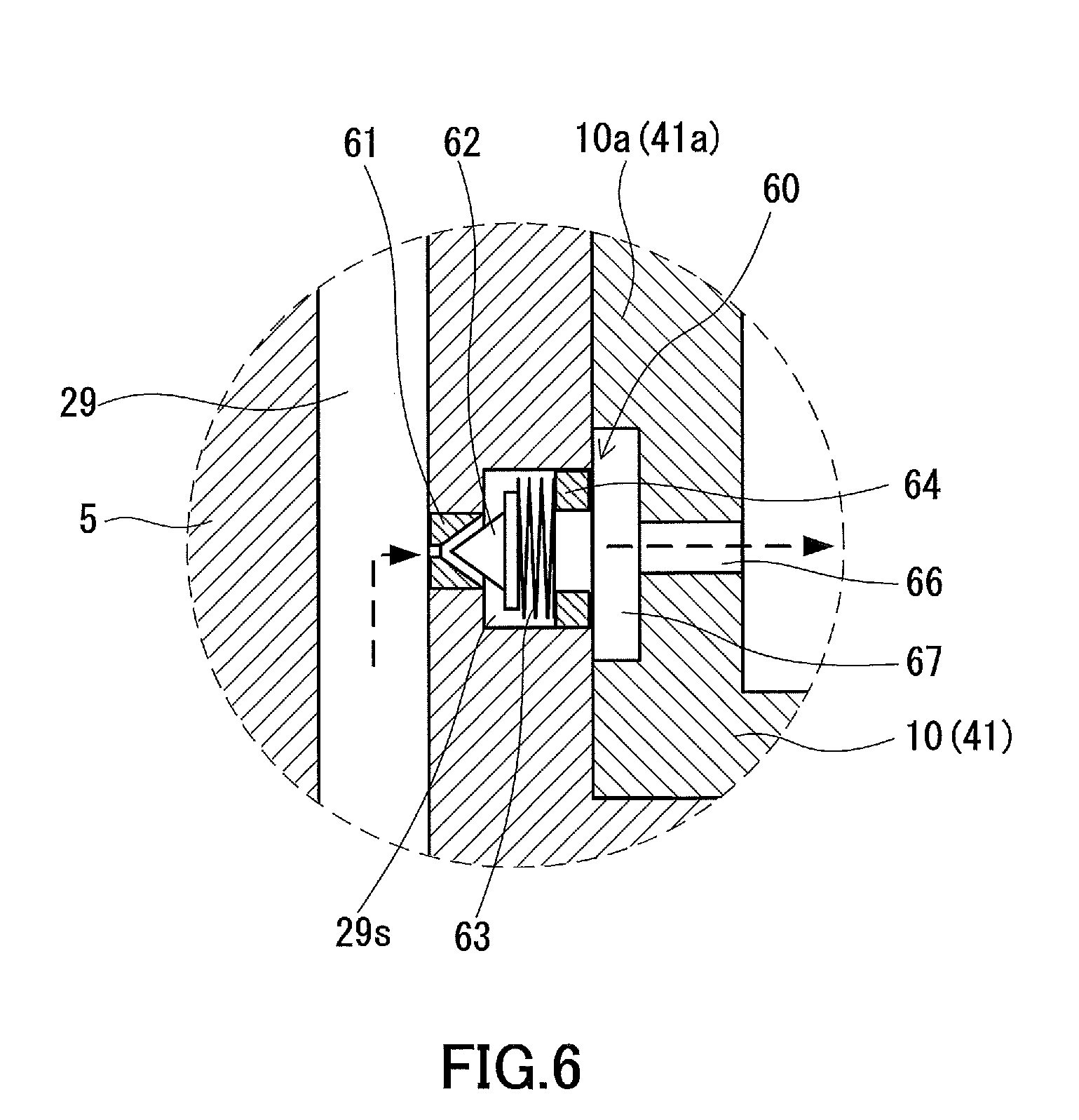
[0038] FIG. 6 is a partially enlarged view of FIG. 5.
[0039] FIG. 7 is a vertical cross-sectional view illustrating an expander-integrated compressor according to a third embodiment of the present invention.
[0040] FIG. 8 is a partially enlarged view of FIG. 7.
[0041] FIG. 9 is a vertical cross-sectional view illustrating an expander-integrated compressor according to a fourth embodiment of the present invention.
[0042] FIG. 10 is a configuration diagram of a refrigeration cycle apparatus using the expander-integrated compressor.
[0043] FIG. 11 is a vertical cross-sectional view illustrating a conventional expander-integrated compressor.
BEST MODE FOR CARRYING OUT THE INVENTION
First Embodiment
[0044] FIG. 1 is a vertical cross-sectional view illustrating an expander-integrated compressor according to a first embodiment of the present invention. An expander-integrated compressor 100A has a closed casing 1, a compression mechanism 2, an expansion mechanism 3, a motor 4, a shaft 5, an oil pump 6, and an oil supply amount regulating mechanism 30. The compression mechanism 2 is disposed in a lower part of the closed casing 1. The expansion mechanism 3 is disposed in an upper part of the closed casing 1. The motor 4 is disposed between the compression mechanism 2 and the expansion mechanism 3. The compression mechanism 2, the motor 4, and the expansion mechanism 3 are coupled to each other by the shaft 5 so that mechanical power can be transmitted. The oil pump 6 is provided at a lower portion of the shaft 5. The oil supply amount regulating mechanism 30 is for regulating the amount of the oil to be supplied to the expansion mechanism 3. In the present embodiment, a regulating valve (typically a needle valve) is employed as the oil supply amount regulating mechanism 30.
[0045] The motor 4 drives the shaft 5 to operate the compression mechanism 2. The expansion mechanism 3 recovers mechanical power from the expanding working fluid, and supplies the mechanical power to the shaft 5 to assist the motor 4 to drive the shaft 5. The working fluid is, for example, a refrigerant such as carbon dioxide and hydrofluorocarbon.
[0046] In the present embodiment, the arrangement of the compression mechanism 2, the motor 4, and the expansion mechanism 3 is determined in such a manner that the axis direction of the shaft 5 is in agreement with the vertical direction. However, the positional relationship between the compression mechanism 2 and the expansion mechanism 3 may be opposite of that in the present embodiment. In other words, the compression mechanism 2 may be disposed in an upper part of the closed casing 1, and the expansion mechanism 3 may be disposed in a lower part of the closed casing 1.
[0047] The closed casing 1 has an interior space 24 for accommodating various components. The interior space 24 of the closed casing 1 is filled with the refrigerant compressed by the compression mechanism 2. A bottom portion of the closed casing 1 is utilized as an oil reservoir 25. The oil is used for ensuring lubrication and sealing on the sliding parts of the compression mechanism 2 and the expansion mechanism 3. The amount of the oil in the oil reservoir 25 is controlled so that the oil level is below the motor 4. This prevents a decrease of the efficiency of the motor and an increase of the oil discharge amount to the refrigerant circuit, which result from the agitation of the oil by the rotor of the motor 4. Since the temperature of the compression mechanism 2 becomes high during operation of the expander-integrated compressor 100A, the temperature of the oil held in the oil reservoir 25 becomes accordingly high.
[0048] The compression mechanism 2 has cylinders 17 and 18, pistons 7 and 8, and bearing members 10 and 11, and it has the same structure as that of the conventional two-stage rotary compressor. A suction pipe 13 is connected to the cylinder 17, and a suction pipe 14 is connected to the cylinder 18. The refrigerant is guided to compression chambers 19 and 20, formed in the respective cylinders 17 and 18, through the suction pipes 13 and 14. The refrigerant compressed in the compression chambers 19 and 20 is discharged to the interior space 24 of the closed casing 19. A discharge pipe 15 is connected to the closed casing 1 so that an opening thereof is located between the motor 4 and the expansion mechanism 3. The refrigerant discharged to the interior space 24 flows upward through a region surrounding the motor 4. The refrigerant is then guided through the discharge pipe 15 to a flow passage outside the closed casing 1. At that time, the refrigerant and the oil can be separated from each other by a gravitational force or a centrifugal force.
[0049] In the present embodiment, a rotary-type fluid mechanism is employed as the compression mechanism 2. The "rotary type" includes not only a rolling piston type, in which a vane slides along the outer circumferential surface of a piston, and a sliding vane type, in which a vane slides along the inner circumferential surface of a cylinder, but also a swing piston type, in which a piston and a vane are integrally formed. In addition, the type of the compression mechanism 2 is not limited to the rotary type. It is also possible to employ other types of fluid mechanisms, such as a scroll type, a reciprocating type, and a screw type, as the compression mechanism 2. The same applies to the later-described expansion mechanism 3.
[0050] The motor 4 has a stator 21 fixed to the closed casing 1 and a rotor 22 fixed to the shaft 5. Electric power is supplied to the motor 4 through a terminal (not shown) disposed at the top of the closed casing 1.
[0051] An oil supply passage 29 communicating with sliding parts of the expansion mechanism 3 is formed in the shaft 5 so as to extend in the axis direction. This is desirable because, when forming the oil supply passage 29 inside the shaft 5, the problems associated with an increase in the parts count and parts layout do not arise. The oil is supplied to sliding parts of the expansion mechanism 3 through the oil supply passage 29.
[0052] In the present embodiment, the oil supply passage 29 does not open in the upper end face of the shaft 5. In this way, the oil does not flow out over the expansion mechanism 3, unlike the conventional example described with reference to FIG. 11. Thereby, the oil is less easily cooled by the expansion mechanism 3. In other words, the heat transfer from the compression mechanism 2 to the expansion mechanism 3 can be reduced more effectively. However, the oil supply passage 29 may open in the upper end face of the shaft 5.
[0053] The shaft 5 may be made of a single component, or may be made by combining (coupling) a plurality of components together. Specifically, the shaft 5 may include a first shaft on the compression mechanism 2 side and a second shaft on the expansion mechanism 3 side. The first shaft and the second shaft may be coupled directly by fitting them onto each other, or may be coupled to each other via another component (coupler). When the shaft 5 is made of a combination of a plurality of components, assembling, especially alignment between the compression mechanism 2 and the expansion mechanism 3, becomes easy.
[0054] The expansion mechanism 3 has a first cylinder 42, a second cylinder 44 having an inner diameter larger than the inner diameter of the first cylinder 42, an intermediate plate 43 partitioning the first cylinder 42 and the second cylinder 44. The first cylinder 42 and the second cylinder 44 are disposed concentrically with each other. As illustrated in FIGS. 2A and 2B, the expansion mechanism 3 further has a first piston 46, a first vane 48, a first spring 50, a second piston 47, a second vane 49, and a second spring 51.
[0055] As illustrated in FIG. 2A, the first piston 46 is fitted with an eccentric portion 5c of the shaft 5, and it performs eccentric rotational motion in the first cylinder 42. The first vane 48 is retained reciprocably in a vane groove 42a formed in the first cylinder 42. One end of the first vane 48 is in contact with the first piston 46. The first spring 50 is in contact with the other end of the first vane 48, and biases the first vane 48 toward the first piston 46.
[0056] As illustrated in FIG. 2B, the second piston 47 is fitted with an eccentric portion 5d of the shaft 5, and it performs eccentric rotational motion in the second cylinder 44. The second vane 49 is retained reciprocably in a vane groove 44a formed in the second cylinder 44. One end of the second vane 49 is in contact with the second piston 47. The second spring 51 is in contact with the other end of the second vane 49, and biases the second vane 49 toward the second piston 47.
[0057] The expansion mechanism 3 further has a bearing member 45 and a bearing member 41. The bearing member 41 is fitted to the closed casing 1 with no clearance between them. The components such as the cylinders and the intermediate plate are fixed to the closed casing 1 via the bearing member 41. The bearing member 41 and the intermediate plate 43 sandwiches the first cylinder 42 from the top and bottom, and the intermediate plate 43 and the bearing member 45 sandwiches the second cylinder 44 from the top and bottom. Sandwiching the bearing member 45, the intermediate plate 43, and the bearing member 41 forms working chambers 55 and 56 in the first cylinder 42 and the second cylinder 44, respectively.
[0058] As illustrated in FIG. 2A, a suction-side working chamber 55a (first suction-side space) and a discharge-side working chamber 55b (first discharge-side space) are formed inside the first cylinder 42. The working chamber 55a and the working chamber 55b are partitioned by the first piston 46 and the first vane 48. As illustrated in FIG. 2B, a suction-side working chamber 56a (second suction-side space) and a discharge-side working chamber 56b (second discharge-side space) are formed inside the second cylinder 44. The working chamber 56a and the working chamber 56b are partitioned by the second piston 47 and the second vane 49. The total volumetric capacity of the two working chambers 56a and 56b in the second cylinder 44 is greater than the total volumetric capacity of the two working chambers 55a and 55b in the first cylinder 42. The discharge-side working chamber 55b of the first cylinder 42 and the suction-side working chamber 56a of the second cylinder 44 are brought into communication with each other through a through hole 43a formed in the intermediate plate 43, so that they can function as a single working chamber (an expansion chamber).
[0059] The method for making the total volumetric capacity of the working chambers 56a and 56b greater than the total volumetric capacity of the working chambers 55a and 55b is not limited to the method of varying the inner diameters of the first cylinder 42 and the second cylinder 44. It is also possible to employ the method of appropriately setting the thicknesses of the cylinders 42 and 44 or the outer diameters of the pistons 46 and 47.
[0060] The expansion mechanism 3 further has a suction pipe 52 serving as a suction passage for directly drawing the refrigerant that has not yet been expanded from a flow passage external to the closed casing 1, and a discharge pipe 53 serving as a discharge passage for directly discharging the refrigerant that has been expanded to a flow passage external to the closed casing 1. Specifically, the suction pipe 52 is directly inserted in the first cylinder 42 so that the refrigerant can be guided from the flow passage external to the closed casing 1 to the working chamber 55 of the first cylinder 42. The discharge pipe 53 is directly inserted in the second cylinder 44 so that the refrigerant can be guided from the working chamber 56 of the second cylinder 44 to the flow passage external to the closed casing 1. The suction pipe 52 may be inserted in the bearing member 41, and the discharge pipe 53 may be inserted in the bearing member 45.
[0061] The refrigerant that has not yet been expanded passes through the suction pipe 52 and flows into the working chamber 55a of the first cylinder 42. The working fluid having flowed into the working chamber 55a of the first cylinder 42 moves to the working chamber 55b in association with rotation of the shaft 5, and it expands and reduces its pressure in the expansion chamber formed by the working chamber 55b, the through hole 43a, and the working chamber 56a, while rotating the shaft 5. The refrigerant having expanded is guided to the outside of the closed casing 1 through the working chamber 56b and the discharge pipe 53.
[0062] The location at which the oil pump 6 is provided is a lower portion of the shaft 5. Specifically, the oil pump 6 is disposed in the oil supply passage 29 in a lower portion of the shaft 5. Disposing the oil pump 6 in the oil supply passage 29 eliminates the need to provide an oil supply pipe separately.
[0063] The oil pump 6 is operated by the mechanical power supplied from the shaft 5. In the present embodiment, a velocity type pump (turbine pump) is employed as the oil pump 6. Specifically, the oil pump 6 has a pump blade 6a and a blade stopper 6b. The pump blade 6a is fixed to the shaft 5 by the blade stopper 6b. Rotation of the pump blade 6a together with the shaft 5 causes the oil to be pumped upward. Generally, the rotation speed of the oil pump 6 is equal to the rotation speed of the shaft 5. Therefore, as the rotation speed of the shaft 5 increases, the delivery capacity and delivery pressure of the oil pump 6 increases accordingly. However, since the effectiveness of the oil supply amount regulating mechanism 30 increases as the delivery pressure of the oil pump 6 increases, the amount of the oil to be supplied to the expansion mechanism 3 is not proportional to the rotation speed of the shaft 5.
[0064] The type of the oil pump is not limited to the velocity type pump, and a positive displacement pump may be used. Examples of the positive displacement pump include a rotary type oil pump and a TROCHOID pump (registered trademark of Nippon Oil Pump Co., Ltd.). However, the velocity type pump is better suited for the oil supply amount regulating mechanism 30 in the present embodiment than the positive displacement pump. The reason is that no oil escape route is provided in the present embodiment, as it is provided in the later-described second and third embodiments.
[0065] The oil supply amount regulating mechanism 30 includes a structure for preventing the amount of the oil to be supplied to the expansion mechanism 3 through the oil supply passage 29 from increasing correspondingly to an increase of the rotation speed of the shaft 5. As described previously, it is important to reduce the heat transfer from the compression mechanism 2 to the expansion mechanism 3 resulting from the oil circulation as much as possible, in order to improve the efficiency of a refrigeration cycle apparatus (see FIG. 10) using the expander-integrated compressor 100A. When the rotation speed of the shaft 5 increases, the delivery capacity and delivery pressure of the oil pump 6 tend to increase. However, excessive supply of the oil is prevented by the workings of the oil supply amount regulating mechanism 30. In some cases, the oil supply amount to the expansion mechanism 3 can be maintained at almost a constant level regardless of the rotation speed of the shaft 5. As a result, it is possible to reduce the heat transfer from the compression mechanism 2 to the expansion mechanism 3 that results from the oil circulation.
[0066] In the present embodiment, the oil supply amount regulating mechanism 30 is provided in the oil supply passage 29. For this reason, it is unnecessary to provide a dedicated space for the oil supply amount regulating mechanism 30. The location at which the oil supply amount regulating mechanism 30 should be provided may be below the expansion mechanism 3, which is located in the upper part of the closed casing 1. Typically, the oil supply amount regulating mechanism 30 is provided between the working chamber 20 of the compression mechanism 2 and the motor 4 with respect to the axis direction of the shaft 5.
[0067] FIG. 3 is a partially enlarged view of FIG. 1. As illustrated in FIG. 3, the oil supply amount regulating mechanism 30 has a valve seat 31, a needle 32 (valve body), a spring 33, and a needle stopper 34. The valve seat 31 has an orifice shape whose inner diameter decreases toward the expansion mechanism 3. The needle 32 is disposed so as to face the valve seat 31. The needle 32 has a leading end portion in a circular conic shape. The spring 33 is disposed between the valve seat 31 and the needle 32 so that a gap through which the oil can flow is formed between the valve seat 31 and the needle 32. The spring 33 expands and contracts according to a pressure change of the oil in the oil supply passage 29, so that the gap between the valve seat 31 and the needle 32 can be adjusted. The needle stopper 34 for defining the range of motion of the needle 32 is disposed opposite the valve seat 31 across the needle 32. The valve seat 31 or the needle stopper 34 may be formed by a portion of the shaft 5.
[0068] With the oil supply amount regulating mechanism 30, the oil to be supplied to the expansion mechanism 3 flows through the oil supply passage 29 and hits the back face of the needle 32. Thereafter, the oil passes through the surrounding region of the needle 32 and flows toward the valve seat 31. The oil hitting the back face of the needle 32 presses the needle 32 toward the valve seat 31 with a force corresponding to the flow rate of the oil. The needle 32 is pushed back with a force in proportion to the displacement of the spring 33. Specifically, the area of the gap between the valve seat 31 and the needle 32 (the cross-sectional area of the gap) changes according to the flow rate of the oil. While the oil feeding capability of the oil pump 6 becomes higher in proportional to an increase of the rotation speed of the shaft 5, the resistance to the oil flow increases because the gap between the valve seat 31 and the needle 32 narrows. As a result, the amount of the oil to be supplied is restricted (optimized).
[0069] Even when the shaft 5 revolves at a high speed, an unnecessarily great amount of the oil is not supplied to the expansion mechanism 3 because of the workings of the oil supply amount regulating mechanism 30. In other words, an appropriate amount of the oil can be supplied to the expansion mechanism 3. As a result, it is possible to reduce the heat transfer from the compression mechanism 2 to the expansion mechanism 3 that results from the oil circulation. Moreover, since excess oil is not supplied to the expansion mechanism 3, it is possible to prevent the working fluid from mixing with a large amount of the oil in the expansion mechanism 3. Thus, it is possible to prevent a considerable decrease in heat exchange efficiency resulting from the excess oil flowing into an evaporator 102 (see FIG. 10). As illustrated in FIG. 4, the effect of optimizing the oil supply amount can be obtained by providing only the valve seat 31 in the oil supply passage 29. That is, by merely providing an orifice in the oil supply passage 29, the oil can be prevented from being excessively supplied to the expansion mechanism 3 because the pressure loss at the orifice increases proportionally to an increase of the oil flow rate.
[0070] In the present embodiment, the oil of the oil supply passage 29 is supplied only to the expansion mechanism 3. However, the oil of the oil supply passage 29 may also be supplied to the compression mechanism 2.
Second Embodiment
[0071] FIG. 5 is a vertical cross-sectional view illustrating an expander-integrated compressor according to a second embodiment of the present invention. As illustrated in FIG. 5, a main difference between an expander-integrated compressor 100B of the present embodiment and the expander-integrated compressor 100A of the first embodiment is in the oil supply amount regulating mechanism. The same parts as those in the embodiment shown in FIG. 1 will be designated by the same reference numerals, and the descriptions thereof will be omitted.
[0072] FIG. 6 is a partially enlarged view of FIG. 5. In the present embodiment, a branch passage 29s branching in a radial direction from the oil supply passage 29 and opening in an outer circumferential surface of the shaft 5 is formed in the shaft 5. An oil supply amount regulating mechanism 60 is provided in the branch passage 29s. In this way, mounting of the oil supply amount regulating mechanism 60 is possible from the outside of the shaft 5, so assembling is easier than that in the first embodiment. Moreover, this is suitable also in the case where the oil pump is a positive displacement pump because the branch passage 29s behaves as an oil escape route.
[0073] As illustrated in FIG. 6, the oil supply amount regulating mechanism 60 has a valve seat 61, a needle 62, a spring 63, and a needle stopper 64. The valve seat 61 has an orifice shape whose inner diameter decreases toward the oil supply passage 29. The valve seat 61 is disposed at a portion of the branch passage 29s that faces the oil supply passage 29. The needle 62 in a circular conic shape is disposed so as to face the valve seat 61. The needle 62 is displaceable in a direction toward the valve seat 61 and a direction away from the valve seat 61 (radial directions of the shaft 5). The needle stopper 64 is disposed at a portion of the branch passage 29s that faces an outside of the shaft 5. The needle stopper 64 defines the range of motion of the needle 62. The spring 63 is disposed between the needle 62 and the needle stopper 64.
[0074] A bearing member 10 has a bearing portion 10a that supports the shaft 5. The bearing portion 10a covers an outer circumferential surface of the shaft 5 at a location where the branch passage 29s is formed. A circular chamber 67 is formed in an inner circumferential surface of the bearing portion 10a. The branch passage 29s opens toward the chamber 67. An oil discharge passage 66 for connecting the chamber 67 and the interior space 24 of the closed casing 1 is further formed in the bearing portion 10a so as to penetrate through the bearing portion 10a in a radial direction. By the branch passage 29s, the chamber 67, and the oil discharge passage 66, the oil can flow from the oil supply passage 29 to the interior space 24 of the closed casing 1.
[0075] When the internal pressure of the oil supply passage 29 is lower than a predetermined pressure, the oil supply amount regulating mechanism 60 is brought to a closed state. The closed state refers to a state in which the branch passage 29s is closed by the needle 62 being fitted into the valve seat 61. In the closed state, the oil cannot flow through the branch passage 29s. On the other hand, when the rotation speed of the shaft 5 increases and the internal pressure of the oil supply passage 29 thereby becomes higher than a predetermined pressure, the oil supply amount regulating mechanism 60 is brought to an open state. The open state refers to a state in which the needle 62 is detached from the valve seat 61 so that a gap is formed between the valve seat 61 and the needle 62. In the open state, the oil can flow through the branch passage 29s.
[0076] When the internal pressure of the oil supply passage 29 becomes higher than the predetermined pressure, the oil enters the branch passage 29s through the valve seat 61 while displacing the needle 62. The force of the oil that displaces the needle 62 is proportional to the internal pressure of the oil supply passage 29. On the condition that the outward load that is applied to the needle 62 by the oil in the oil supply passage 29 and the like (more specifically, the pressure of the oil and the centrifugal force) exceeds the force by which the spring 63 pushes the needle 62 when the oil supply amount regulating mechanism 60 is in the closed state, the oil supply amount regulating mechanism 60 switches from the closed state to the open state.
[0077] In other words, when the rotation speed of the shaft 5 increases and the oil is fed into the oil supply passage 29 in an amount greater than is necessary, the increase of the internal pressure of the oil supply passage 29 brings the oil supply amount regulating mechanism 60 into the open state. When the oil supply amount regulating mechanism 60 is brought into the open state, part of the oil flowing through the oil supply passage 29 is guided to the outside of the shaft 5 through the branch passage 29s. The oil having flowed out of the shaft 5 is discharged to the interior space 24 of the closed casing 1 through the chamber 67 and the oil discharge passage 66 formed in the bearing portion 10a of the bearing member 10. As a result, the amount of the oil to be supplied to the expansion mechanism 3 is optimized. Thus, in the present embodiment, the oil supply amount regulating mechanism 60 is constructed by a relief valve.
[0078] In addition, in the present embodiment, the oil is allowed to escape to the outside of the shaft 5 through the branch passage 29s. For this reason, when the oil supply amount regulating mechanism 60 is brought into the open state, a difference in the flow rate of the oil in the oil supply passage 29 arises between the positions before and after the oil supply amount regulating mechanism 60. Specifically, the flow rate is high between the oil supply amount regulating mechanism 60 and the oil pump 6, and the flow rate is low between the expansion mechanism 3 and the oil supply amount regulating mechanism 60. It is preferable that the portion at which the flow rate of the oil is high be farther away from the expansion mechanism 3, from the view point of reducing the heat transfer from the compression mechanism 2 to the expansion mechanism 3 that results from the oil circulation. Therefore, it is desirable that the branch passage 29s be formed in a portion of the shaft 5 that is between the motor 4 and the compression mechanism 2.
Third Embodiment
[0079] FIG. 7 is a vertical cross-sectional view illustrating an expander-integrated compressor according to a third embodiment of the present invention. As illustrated in FIG. 7, a main difference between an expander-integrated compressor 100C of the present embodiment and the expander-integrated compressor 100A of the first embodiment is in the oil supply amount regulating mechanism.
[0080] FIG. 8 is a partially enlarged view of FIG. 7. In the present embodiment, a branch passage 29t branching in a radial direction from the oil supply passage 29 and opening in an outer circumferential surface of the shaft 5 is formed in the shaft 5. An oil supply amount regulating mechanism 70 is provided exteriorly of the shaft so that the oil is guided to the interior space 24 of the closed casing 1 through the branch passage 29t. Since the oil supply amount regulating mechanism 70 is provided exteriorly of the shaft 5, a larger space than is available in the preceding two embodiments can be ensured for the oil supply amount regulating mechanism 70.
[0081] The present embodiment is similar to the second embodiment in the respect that the branch passage 29t is formed in the shaft 5 as an oil escape route. On the other hand, the present embodiment is different from the second embodiment in the respect that the oil supply amount regulating mechanism 70 does not rotate together with the shaft 5. This is suitable also in the case where the oil pump is a positive displacement pump because the branch passage 29t behaves as an oil escape route.
[0082] As illustrated in FIG. 8, in the present embodiment, the oil supply amount regulating mechanism 70 is provided inside the bearing member 10. The bearing member 10 has the bearing portion 10a that supports the shaft 5. The bearing portion 10a covers an outer circumferential surface of the shaft 5 at a location where the branch passage 29t is formed. A circular chamber 77 is formed in an inner circumferential surface of the bearing portion 10a. The branch passage 29t opens toward the chamber 77. An oil discharge passage 76 is further formed in the bearing portion 10a, as a passage for connecting the chamber 77 and the interior space 24 of the closed casing 1. The oil supply amount regulating mechanism 70 is provided in the oil discharge passage 76.
[0083] The oil supply amount regulating mechanism 70 has a valve seat 71, a valve body 72, a spring 73, and a valve body stopper 74. The oil discharge passage 76 includes a portion having a T-shaped cross-sectional shape along the flow direction of the oil. The valve seat 71 is disposed in the T-shaped portion. The valve body 72 in a spherical shape is disposed so as to face the valve seat 71. The valve body stopper 74 is disposed opposite the valve seat 71 across the valve body 72. The valve body stopper 74 defines the range of motion of the valve body 72. The spring 73 is disposed between the valve body 72 and the valve body stopper 74. It should be noted that the structure of the oil supply amount regulating mechanism 70 may be the same as that in the second embodiment.
[0084] When the internal pressure of the oil supply passage 29 is lower than a predetermined pressure, the oil supply amount regulating mechanism 70 is brought to a closed state. The closed state refers to a state in which the oil discharge passage 76 is closed by the valve body 72 being fitted into the valve seat 71. In the closed state, the oil cannot flow through the oil discharge passage 76. On the other hand, when the rotation speed of the shaft 5 increases and the internal pressure of the oil supply passage 29 thereby becomes higher than the predetermined pressure, the oil supply amount regulating mechanism 70 is brought to an open state. The open state refers to a state in which the valve body 72 is detached from the valve seat 71 so that a gap is formed between the valve seat 71 and the valve body 72. In the open state, the oil can flow through the oil discharge passage 76.
[0085] When the internal pressure of the oil supply passage 29 becomes higher than the predetermined pressure, the oil displaces the valve body 72, causing the oil discharge passage 76 to open. The force of the oil that displaces the valve body 72 is proportional to the internal pressure of the oil supply passage 29. On the condition that the load that is applied to the valve body 72 by the oil in the oil supply passage 29 exceeds the force by which the spring 73 pushes the needle 72 when the oil supply amount regulating mechanism 70 is in the closed state, the oil supply amount regulating mechanism 70 switches from the closed state to the open state.
[0086] In other words, when the rotation speed of the shaft 5 increases and the oil is fed into the oil supply passage 29 in an amount greater than is necessary, the increase of the internal pressure of the oil supply passage 29 brings the oil supply amount regulating mechanism 70 into the open state. When the oil supply amount regulating mechanism 70 is brought into the open state, part of the oil flowing through the oil supply passage 29 is guided to the outside of the shaft 5 through the branch passage 29t. The oil having flowed out of the shaft 5 is discharged to the interior space 24 of the closed casing 1 through the chamber 77 and the oil discharge passage 76 each formed in the bearing portion 10a of the bearing member 10. As a result, the amount of the oil to be supplied to the expansion mechanism 3 is optimized. Thus, in the present embodiment as well, the oil supply amount regulating mechanism 70 is constructed by a relief valve.
[0087] It should be noted that the oil supply amount regulating mechanism 70 may be disposed at an outlet of the oil discharge passage 76, or may be disposed in the chamber 77.
[0088] In the present embodiment as well, the oil is allowed to escape to the outside of the shaft 5 through the branch passage 29t. Therefore, it is desirable that the branch passage 29t be formed in a portion of the shaft 5 that is between the motor 4 and the compression mechanism 2, which is located in the lower part of the closed casing 1.
Fourth Embodiment
[0089] In an expander-integrated compressor 100D of the present embodiment, the axis direction of the shaft 5 is parallel to the horizontal direction, as illustrated in FIG. 9. The oil reservoir 25 is formed along the longitudinal direction of the closed casing 1. A partition wall 27 is provided between the expansion mechanism 3 and the motor 4. The partition wall 27 divides the interior space 24 into a space on the expansion mechanism 3 side and a space on the compression mechanism 2 side. The motor 4 is disposed also in the space on the compression mechanism 2 side. This partition wall 27 also has the function to reduce the heat transfer from the compression mechanism 2 and the motor 4 to the expansion mechanism 3. The partition wall 27 has a passage 27h allowing the oil to flow therethrough.
[0090] A positive displacement-type the oil pump 26 is provided at an end portion of the shaft 5. The oil pump 26, the expansion mechanism 3, the motor 4, and the compression mechanism 2 are arrayed in that order along the axis direction of the shaft 5. The oil supply amount regulating mechanism 60 is the same one as described with reference to FIG. 6 in the third embodiment. A nozzle 26k of the oil pump 26 extends toward the oil reservoir 25 so that it can draw the oil in the oil reservoir 25. The oil drawn by the oil pump 26 is supplied through the oil supply passage 29 to the compression mechanism 2 located in the far side, viewed from the oil pump 26, with respect to the axis direction the shaft 5. In the present embodiment, the oil from the oil pump 26 is also supplied to the expansion mechanism 3, which is located on the near side, viewed from the oil pump 26. The oil discharged from the oil supply passage 29 through the oil supply amount regulating mechanism 60 returns to the space on the expansion mechanism 3 side.
[0091] As in the foregoing embodiments, the oil supply amount regulating mechanism 60 prevents excessive supply of the oil. Thereby, the heat transfer from the compression mechanism 2 to the expansion mechanism 3 is suppressed. In the embodiment shown in FIG. 9, the oil pump 26 is provided in the expansion mechanism 3 side. However, it is possible to provide the oil pump 26 in the compression mechanism 2 side. It is also possible to provide the oil supply amount regulating mechanism 30 (first embodiment) or the oil supply amount regulating mechanism 70 (third embodiment), in place of the oil supply amount regulating mechanism 60.
INDUSTRIAL APPLICABILITY
[0092] The expander-integrated compressor according to the present invention may be suitably applied to, for example, refrigeration cycle apparatuses (heat pumps) for air conditioners, water heaters, driers, or refrigerator-freezers. As illustrated in FIG. 10, a refrigeration cycle apparatus 110 includes: an expander-integrated compressor 100A (, 100B, 100C, or 100D); a radiator 101 for cooling the refrigerant compressed by the compression mechanism 2; and an evaporator 114 for evaporating the refrigerant expanded by the expansion mechanism 3. The compression mechanism 2, the radiator 101, the expansion mechanism 3, and the evaporator 102 are connected by pipes, to form a refrigerant circuit.
[0093] For example, when refrigeration cycle apparatus 110 is applied to an air conditioner, it is possible to prevent a decrease in heating capacity caused by a decreased discharge temperature of the compression mechanism 2 during heating operation, and a decrease in cooling capacity caused by an increased discharge temperature of the expansion mechanism 3 during cooling operation, by reducing the heat transfer from the compression mechanism 2 to the expansion mechanism 3. As a result, the coefficient of performance of the air conditioner is improved.
* * * * *
D00000
D00001
D00002
D00003
D00004
D00005
D00006
D00007
D00008
D00009
D00010
XML
uspto.report is an independent third-party trademark research tool that is not affiliated, endorsed, or sponsored by the United States Patent and Trademark Office (USPTO) or any other governmental organization. The information provided by uspto.report is based on publicly available data at the time of writing and is intended for informational purposes only.
While we strive to provide accurate and up-to-date information, we do not guarantee the accuracy, completeness, reliability, or suitability of the information displayed on this site. The use of this site is at your own risk. Any reliance you place on such information is therefore strictly at your own risk.
All official trademark data, including owner information, should be verified by visiting the official USPTO website at www.uspto.gov. This site is not intended to replace professional legal advice and should not be used as a substitute for consulting with a legal professional who is knowledgeable about trademark law.