Dehumidifier for Use in Water Damage Restoration
Stamm; Stephen ; et al.
U.S. patent application number 12/821958 was filed with the patent office on 2010-12-30 for dehumidifier for use in water damage restoration. This patent application is currently assigned to Karcher North America, Inc.. Invention is credited to Nicholas Brian O'Kane, Doug Shipe, Stephen Stamm.
| Application Number | 20100326103 12/821958 |
| Document ID | / |
| Family ID | 43379259 |
| Filed Date | 2010-12-30 |


View All Diagrams
| United States Patent Application | 20100326103 |
| Kind Code | A1 |
| Stamm; Stephen ; et al. | December 30, 2010 |
Dehumidifier for Use in Water Damage Restoration
Abstract
A transportable dehumidifier system is provided that employs a thermal expansion valve to control the flow of refrigerant therethrough.
| Inventors: | Stamm; Stephen; (Wheat Ridge, CO) ; Shipe; Doug; (Highlands Ranch, CO) ; O'Kane; Nicholas Brian; (Highlands Ranch, CO) |
| Correspondence Address: |
    SHERIDAN ROSS PC
    1560 BROADWAY, SUITE 1200
    DENVER
    CO
    80202
    US
|
| Assignee: | Karcher North America, Inc. Englewood CO |
| Family ID: | 43379259 |
| Appl. No.: | 12/821958 |
| Filed: | June 23, 2010 |
Related U.S. Patent Documents
| Application Number | Filing Date | Patent Number | ||
|---|---|---|---|---|
| 61219888 | Jun 24, 2009 | |||
| Current U.S. Class: | 62/176.6 ; 62/222; 62/498; 62/513 |
| Current CPC Class: | F25B 2600/2513 20130101; F24F 2221/125 20130101; F24F 3/1405 20130101 |
| Class at Publication: | 62/176.6 ; 62/498; 62/222; 62/513 |
| International Class: | F25B 49/02 20060101 F25B049/02; F25B 1/00 20060101 F25B001/00; F25B 41/04 20060101 F25B041/04; F25B 41/00 20060101 F25B041/00 |
Claims
1. A portable dehumidifier, comprising: a housing having an inlet opening for receiving air of a first humidity and an exit opening for expelling air of a second humidity; an evaporator positioned adjacent to said inlet opening, said evaporator having an inlet tube and an outlet tube; a compressor interconnected to the evaporator via a outlet tube of the evaporator, the compressor having an exit tube; a condenser interconnected to the exit tube of the compressor, the condenser having an exit tube that is interconnected to a thermal expansion valve that is also associated with the inlet tube of the evaporator; a sensor associated with the exit tube of the evaporator; and wherein the sensor communicates with the thermal expansion valve to control flow of refrigerant flowing through the evaporator, compressor, and tubes.
2. The portable dehumidifier of claim 1, wherein said evaporator is a heat exchanger that employs fins and tubes or micro channels.
3. The portable dehumidifier of claim 1, wherein said condenser is a heat exchanger that employs fins and tubes or micro channels.
4. The portable dehumidifier of claim 1, further comprising a pump that is associated with a reservoir that receives moisture from said evaporator.
5. The portable dehumidifier of claim 1, further comprising a means for chilling air positioned between the inlet opening and the evaporator.
6. The portable dehumidifier of claim 1, further comprising an inlet temperature sensor associated with the inlet opening and an outlet temperature sensor associated with the exit opening.
7. The portable dehumidifier of claim 1, wherein a portion of the housing defines an air path.
8. The portable dehumidifier of claim 1, wherein at least a portion of the housing is removable.
9. A dehumidifier, comprising: an evaporator; a compressor associated with the evaporator; a condenser associated with the compressor; a valve associated with the condenser and the evaporator; a sensor that is associated with the valve; and wherein the sensor communicates with the valve to control flow of refrigerant through the portable dehumidifying system.
10. The dehumidifier of claim 9, wherein said evaporator is a heat exchanger that employs fins and tubes or micro channels.
11. The dehumidifier of claim 9, wherein said condenser is a heat exchanger that employs fins and tubes or micro channels.
12. The dehumidifier of claim 9, further comprising a pump that is associated with a reservoir that receives moisture from said evaporator.
13. The dehumidifier of claim 9, further comprising a means for chilling air positioned between the inlet opening and the evaporator.
14. The portable dehumidifier of claim 9, further comprising an inlet temperature sensor associated with the inlet opening and an outlet temperature sensor associated with the exit opening.
15. The dehumidifier of claim 9, wherein the valve is a thermal expansion valve;
16. The portable dehumidifier of claim 9, further including a housing positioned about the evaporator and the condenser that defines an air path.
17. The portable dehumidifier of claim 16, wherein at least a portion of the housing is removable.
18. A dehumidifier including a compressor for delivering hot compressed refrigerant, a condenser that receives refrigerant from said compressor and condenses same, an expansion device that receives refrigerant from said condenser and expands same, an evaporator that receives refrigerant from the expansion device and evaporating same and delivers the refrigerant to the compressor, the refrigerant being circulated from said compressor to said condenser to said expansion device to said evaporator and back to said compressor in a refrigeration cycle, the improvement comprising: a sensor associated with the evaporator that communicates with the expansion device to control the flow of refrigerant through the dehumidifier.
19. The dehumidifier of claim 18 wherein the system is devoid of a capillary tube.
20. The dehumidifier of claim 18, wherein said evaporator is a heat exchanger that employs fins and tubes or micro channels.
21. The dehumidifier of claim 18, wherein said condenser is a heat exchanger that employs fins and tubes or micro channels.
22. The dehumidifier of claim 18 wherein the evaporator, condenser compressor, expansion device and associated tubes are enclosed with a housing having an airflow path therethrough.
23. The dehumidifier of claim 18, further comprising an inlet temperature sensor associated with an inlet opening of the housing and an outlet temperature sensor associated with an exit opening of the housing.
24. The dehumidifier of claim 18, further comprising an air-to-air heat exchanger associated with an inlet of said dehumidifier that cools air prior to the same entering said evaporator.
25. A portable dehumidifier having a controlled flow of refrigerant through a system employing a refrigeration cycle that employs an evaporator, a compressor interconnected to the evaporator via a first tube, a condenser interconnected to a valve via a second tube and to the compressor via a third tube, a forth tube interconnects the valve to the evaporator and a sensor that is associated with the valve and associated with the fourth tube, comprising: sensing information related to at least one of temperature and humidity; and controlling with the valve the flow of refrigerant through the first, second, third and fourth tubes and the compressor, condenser and evaporator.
26. A portable dehumidifier for removing water from air, comprising: a housing having an inlet opening for receiving air of a first humidity and an exit opening for expelling air of a second humidity; an evaporator positioned adjacent to said inlet opening, said evaporator having an inlet tube and an outlet tube; a compressor interconnected to the evaporator via a outlet tube of the evaporator, the compressor having an exit tube; a condenser interconnected to the exit tube of the compressor, the condenser having an exit tube that is interconnected to a thermal expansion valve that is also associated with the inlet tube of the evaporator; a pump that is associated with a reservoir; and wherein the reservoir includes a sensor that initiates the pump when a fluid introduced into the reservoir reaches a predetermined level and wherein the pump operates after the evaporator ceases dehumidifying air.
Description
CROSS-REFERENCE TO RELATED APPLICATIONS
[0001] The following application claims the benefit of U.S. Provisional Patent Application Ser. No. 61/219,888, filed Jun. 24, 2009, the entire disclosure of which is incorporated by reference herein.
[0002] The following patent application is also related to U.S. Pat. No. 7,281,389, entitled "Enhanced Performance Dehumidifier," U.S. Patent Application Publication No. 2008/0028776, entitled "Enhanced Performance Dehumidifier," U.S. Pat. No. 7,194,870, entitled "High Performance Dehumidifier," U.S. Pat. No. 6,370,902, entitled "Apparatus for Dehumidifying Air," and U.S. Pat. No. 7,246,503 entitled "Enhanced Drying Dehumidifier," the entire disclosures of which are incorporated by reference herein. This application also directs the attention of one skilled in the art to the Micro Channel Heat Exchangers made by Danfoss, which are described at www.danfoss.com.
FIELD OF THE INVENTION
[0003] Embodiments of the present invention are generally related to dehumidifiers, and more particularly to dehumidifiers with improved performance and efficiency. More specifically, one embodiment of the present invention is a transportable dehumidifying system that is placed in areas that have been damaged by water and facilitate drying of the area by removal of humidity from surrounding air. It is anticipated that such devices can be combined with other damage remediation components to form an integrated system useful in efficiently and effectively remediating a water damaged structure.
BACKGROUND OF THE INVENTION
[0004] Dehumidifiers are generally comprised of a compressor, an evaporator and a condenser, linked by a series of tubes to form a continuous refrigerant cycle. The compressor delivers hot compressed refrigerant gas to the condenser that condenses the hot compressed refrigerant gas into hot refrigerant liquid. An expansion device receives the hot refrigerant liquid from the condenser and expands same to reduce the temperature and pressure of the refrigerant. The evaporator receives the cool liquid refrigerant from the expansion device and evaporates same to yield cold gas refrigerant that is returned to the compressor to complete the refrigeration cycle. Air is dehumidified by directing moisture-laden air across the evaporator, which cools the air below the dew point thereof so that water vapor trapped in the air, i.e. humidity, condenses into a liquid. The dehumidified air is then directed across the condenser to warm the air which may be redirected to a water damaged area to facilitate drying of the same. For a concise explanation of dehumidifiers and portable dehumidifiers, please see above-identified U.S. Pat. No. 7,281,398.
[0005] One drawback of existing dehumidifiers is that a capillary tube is often employed to control the flow of refrigerant. This method of control is generally acceptable to control the flow of refrigerant in common applications. Indeed, most dehumidifiers are optimized to perform at 80.degree. F. and 60% relative humidity, a standard set by the association of Home Appliance Manufacturers. However, atmospheric conditions around a portable dehumidifier positioned in an area being dried after water exposure often vary from this optimum condition, which results in system inefficiencies. It is thus desirable to optimize performance of a dehumidifier to employ sensors to monitor temperature and relative humidity of the incoming atmospheric conditions and the dehumidified air.
[0006] The following describes a dehumidifying system that employs a sensor-based system for altering the refrigerant flow in response to external environmental factors.
SUMMARY OF THE INVENTION
[0007] It is one aspect of a present invention to provide a dehumidifier that employs a plurality of sensors coupled with a thermal expansion valve ("TEV") instead of a capillary tube to control refrigerant to flow through the dehumidifier. One embodiment of the present invention employs sensors at the inlet and exhaust locations of the dehumidifier to monitor temperature and relative humidity of the incoming and dehumidified air. A micro-processor evaluates data received from the sensors to determine the appropriate air velocity generated by a fan for maximum performance. More specifically, depending on the needs of the system, the micro-processor is capable of adjusting the flow of air through the dehumidifier by a means of a motor speed controller, etc., a variable related to performance. As one of skill will appreciate, an efficient heat exchange must occur in order for the system to successfully remove humidity from the air regardless of atmospheric condition. This is especially true when the system operates in areas of lower ambient humidity that water restoration dehumidifiers are typically expected to operate.
[0008] In one related embodiment, the TEV is a self-adjusting metering device that controls the refrigerant gas flow to the evaporator. When the dehumidifier is operated at different ambient conditions, the expansion valve responds by opening automatically to provide additional refrigerant. For example, if the ambient temperature is higher than normal, the temperature within the evaporator is restored quickly and efficiently by an increase of refrigerant flow. After the evaporator reaches the proper temperature, the TEV will reduce refrigerant flow. Conversely, capillary tubes of the prior art provide a continuous flow of refrigerant regardless of the ambient conditions and are thus very inefficient.
[0009] Another advantage of using a TEV to control refrigerant flow is the ease of service. More specifically, dehumidifiers that employ capillary tubes require periodic charging with refrigerant gas. If the capillary tube system is not charged precisely, for example, within an ounce of the manufacturer's specification, it will not operate properly. Such precision is not needed when a TEV is employed because it selectively alters refrigerant flow based on the ambient conditions. Variations in operating conditions will be automatically compensated by the TEV to effectuate efficient operations.
[0010] In one embodiment the TEV employs an orifice for the refrigerant flow. The TEV of another embodiment senses the pressure of the refrigerant coming into the evaporator, as well as, the temperature of the refrigerant as it exits the evaporator, then selectively meters the flow of refrigerant into the evaporator. The metering of refrigerant using the pressure of the refrigerant entering the evaporator, as well as, the temperature of the refrigerant as it exits the evaporator assists in moisture grain depression below that of a standard capillary tube dehumidifier system. Moisture grain depression is generally a measurement of water removal from a dehumidification process calculated by subtracting the moisture content of the air exiting the dehumidifier from the moisture content of the air entering the dehumidifier. One of skill in the art will appreciate that the TEV may receive sensor data associated with other components of the refrigerant cycle. For example, information from the processor an/or sensors may be used to control the function of the TEV.
[0011] It is another aspect of the present invention to provide a dehumidifier having an automated shut down cycle. More specifically, condensate taken from the air is collected on the surface of the evaporator and is deposited via gravity into a reservoir. The condensate is periodically pumped from the reservoir when the captured fluid reaches a predetermined level. During shut down of prior art systems, the compressor is turned off and the pump is manually activated to purge the reservoir. However, some condensate will inevitably remain on the surface of the evaporator and will drip into the reservoir after the initial manual purge process is complete. The purge process must then be repeated to fully drain the reservoir. If the reservoir is not drained, the contents thereof may spill when the dehumidifier is moved. One embodiment of the invention preferably employs a shut down button which can be utilized to address these problems. Specifically, when the shut down button is pressed, the compressor is immediately shut off but the pump and the fan continue to run for a short time during which the evaporator coil is restored to a temperature above the dew point which prevents the formation of water thereon. The pump removes the last of the water from the machine, thereby eliminating the spillage problem when the machine is moved. A light may be employed to indicate when the purge process is complete.
[0012] As described above, the pump may also be timer-based. Alternatively, the pump may be sensor-based wherein the pump is activated when the level of the collected water in the reservoir reaches a predetermined level. The reservoir would not need to be removed to be emptied, as the pump would run on a timer circuit when the machine is in shut down mode to ensure that the last of the water is removed from the system.
[0013] The reserve pump of one preferred embodiment also possesses a "safety factor." For example, if in a worst case the dehumidifier were to produce two gallons per hour of condensate, the pump would be rated at six gallons per hour pumping capacity and the timing circuit would operate the pump for twenty seconds each minute to remove the water. Should the amount of water produced be less than the maximum expected, the pump can safely run dry for the expected short period of about twenty seconds per minute or less.
[0014] One embodiment of the present invention addresses the lingering fluid issue by employing an automated shut down cycle that turns off the compressor for a pre-determined amount of time, thereby allowing the condensate to drip from the evaporator. The preferred invention also allows the air mover, i.e. a fan, to remove the maximum amount of condensate possible from the surface of the evaporator into the condensate reservoir. During the final seconds of the automatic shut down cycle, the pump of the system will be activated to ensure that the reservoir is empty and the internal components of the dehumidifier have been substantially purged of condensate. Such a system may only require one button to turn on and off. In the event that a shut down cycle needs to be canceled and the dehumidifier turned on, pressing the button again will reactivate the compressor and cancel the shut down cycle. After the shut down is complete, the machine is ready to be reactivated by pressing the button.
[0015] It is another aspect that a present invention to employ a micro channel condenser that functions similar to a traditional fin/tube heat exchanger but is smaller, lighter and requires less refrigerant charge. Micro channel condensers are more durable and not generally damaged by high pressure washers (which may be used to clean the dehumidifier) that often damage components employing fins/tubes. Furthermore, micro channel condensers are often fabricated of aluminum, as opposed to steel, copper, etc., which reduces weight and size of the overall system and improves refrigeration system efficiencies as quicker temperature response times are achieved.
[0016] It is another aspect that a present invention to provide a dehumidifier having a pre-cooler. More specifically, one embodiment of the present invention employs a pre-cooler that is generally a heat exchanger that employs a fan that directs cooler air through the evaporator, thereby reducing the temperature of the refrigerant flowing therethrough to more efficiently chill the evaporator and pull condensation from the intake air.
[0017] It is another aspect that a present invention to provide a dehumidifier with a removable housing. In one embodiment, the housing is split along an axis associated with the evaporator so that removal of the housing exposes the evaporator. The housing also provides easy access to the other internal components of the device to facilitate cleaning and/or replacement thereof. Furthermore, the housing defines an internal shroud that serves as both an internal duct that directs air to the condenser and evaporator and provides a location for the condensate reservoir.
[0018] It is thus an aspect of embodiments of the present invention to provide a portable dehumidifier, comprising: a housing having an inlet opening for receiving air of a first humidity and an exit opening for expelling air of a second humidity; an evaporator positioned adjacent to said inlet opening, said evaporator having an inlet tube and an outlet tube; a compressor interconnected to the evaporator via a outlet tube of the evaporator, the compressor having an exit tube; a condenser interconnected to the exit tube of the compressor, the condenser having an exit tube that is interconnected to a thermal expansion valve that is also associated with the inlet tube of the evaporator; a sensor associated with the exit tube of the evaporator; and wherein the sensor communicates with the thermal expansion valve to control flow of refrigerant flowing through the evaporator, compressor, compressor and/or associated tubes.
[0019] It is another aspect of the present invention to provide a dehumidifier, comprising: an evaporator; a compressor associated with the evaporator; a condenser associated with the compressor; a valve associated with the condenser and the evaporator; a sensor that is associated with the valve; and wherein the sensor communicates with the valve to control flow of refrigerant through the portable dehumidifying system.
[0020] It is a further aspect of some embodiments of the present invention to provide a dehumidifier including a compressor for delivering hot compressed refrigerant, a condenser that receives refrigerant from said compressor and condenses same, an expansion device that receives refrigerant from said condenser and expands same, an evaporator that receives refrigerant from the expansion device and evaporating same and delivers the refrigerant to the compressor, the refrigerant being circulated from said compressor to said condenser to said expansion device to said evaporator and back to said compressor in a refrigeration cycle, the improvement comprising: a sensor associated with the evaporator that communicates with the expansion device to control the flow of refrigerant through the dehumidifier.
[0021] It is another aspect of the invention to provide a method of controlling flow of refrigerant through a system employing a refrigeration cycle that employs an evaporator, a compressor interconnected to the evaporator via a first tube, a condenser interconnected to a valve via a second tube and to the compressor via a third tube, a forth tube interconnects the valve to the evaporator and a sensor that is associated with the valve and associated with the fourth tube, comprising: sensing information related to at least one of temperature and humidity; and controlling with the valve the flow of refrigerant through the first, second, third and fourth tubes and the compressor, condenser and evaporator.
[0022] The Summary of the Invention is neither intended nor should it be construed as being representative of the full extent and scope of the present invention. Moreover, references made herein to "the present invention" or aspects thereof should be understood to mean certain embodiments of the present invention and should not necessarily be construed as limiting all embodiments to a particular description. The present invention is set forth in various levels of detail in the Summary of the Invention as well as in the attached drawings and the Detailed Description of the Invention and no limitation as to the scope of the present invention is intended by either the inclusion or non-inclusion of elements, components, etc. in this Summary of the Invention. Additional aspects of the present invention will become more readily apparent from the Detail Description, particularly when taken together with the drawings.
BRIEF DESCRIPTION OF THE DRAWINGS
[0023] The accompanying drawings, which are incorporated in and constitute a part of the specification, illustrate embodiments of the invention and together with the general description of the invention given above and the detailed description of the drawings given below, serve to explain the principles of these inventions.
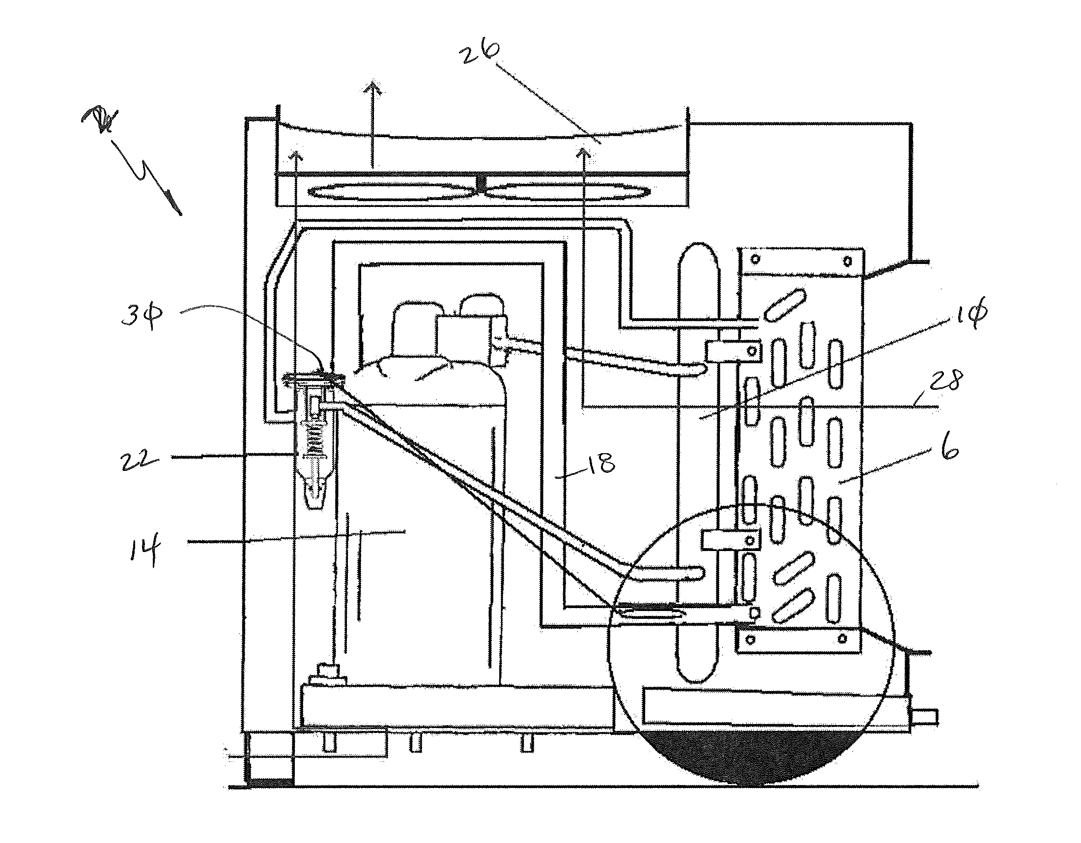
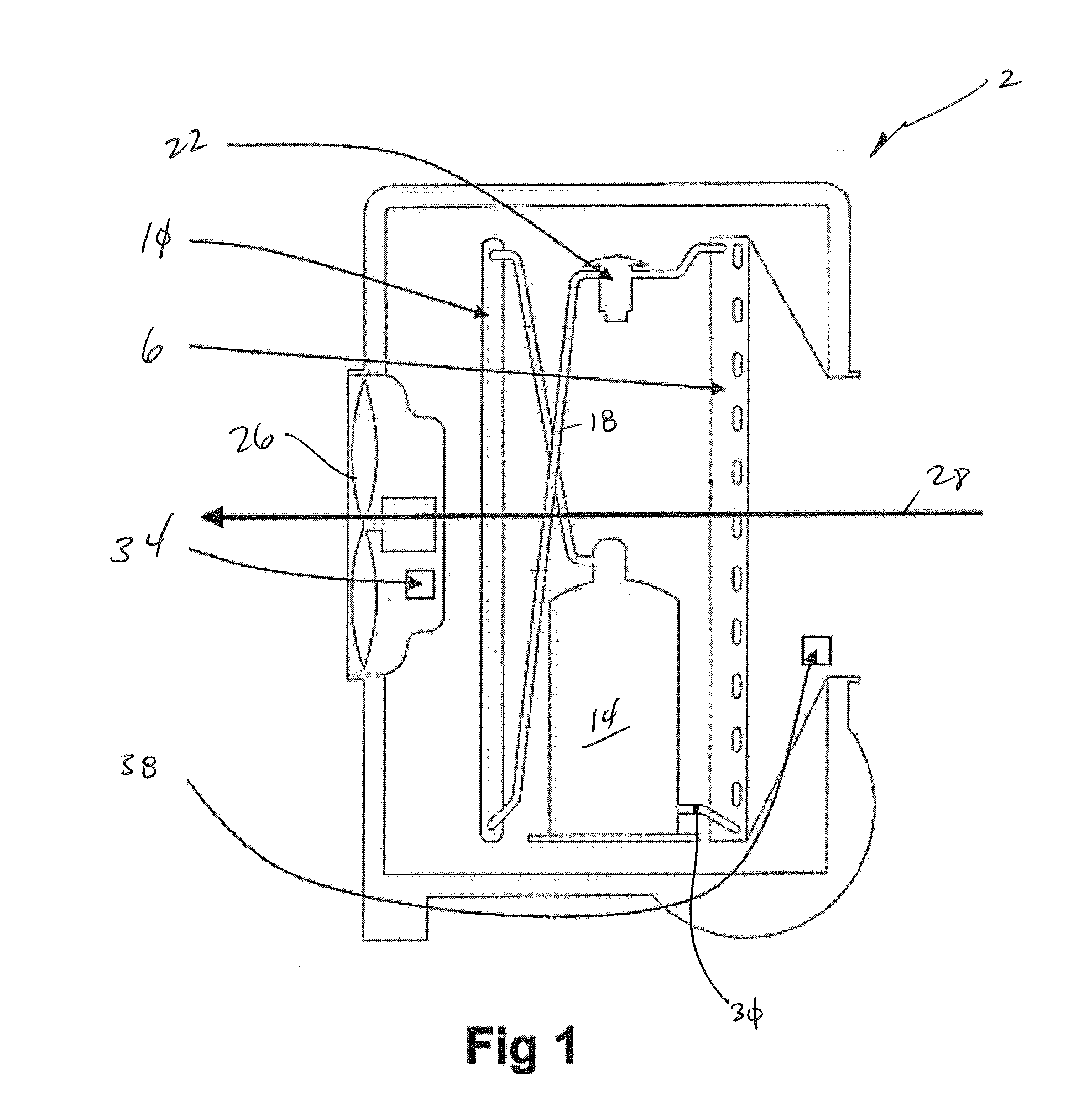
[0024] FIG. 1 is a schematic of a dehumidifier of one embodiment of the present invention that employs a fin/tube evaporator and a micro channel condenser;
[0025] FIG. 2 is a schematic of a dehumidifier of one embodiment of the present invention that employs a fin/tube evaporator and a micro channel condenser;
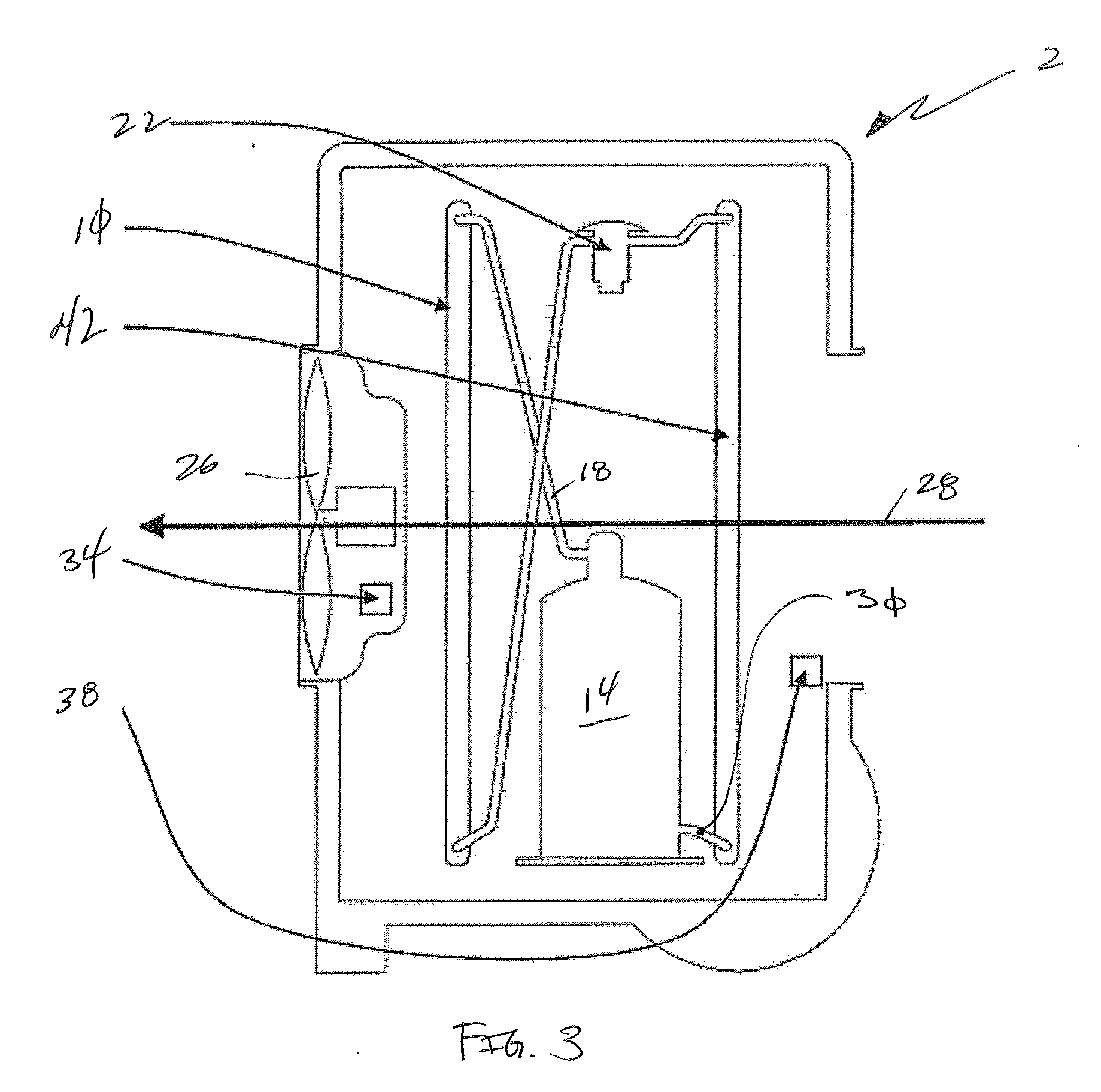
[0026] FIG. 3 is a schematic of a dehumidifier of one embodiment of the present invention that employs a micro channel evaporator and a micro channel condenser;
[0027] FIG. 4 is a schematic of a dehumidifier of one embodiment of the present invention that employs a micro channel evaporator and a micro channel condenser;
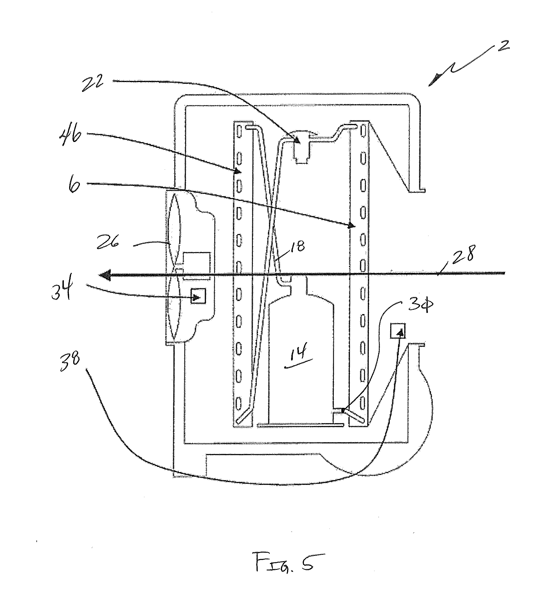
[0028] FIG. 5 is a schematic of a dehumidifier of one embodiment of the present invention that employs a fin/tube evaporator and a fin/tube condenser;
[0029] FIG. 6 is a schematic of a dehumidifier of one embodiment of the present invention that employs a fin/tube evaporator and a fin/tube condenser;
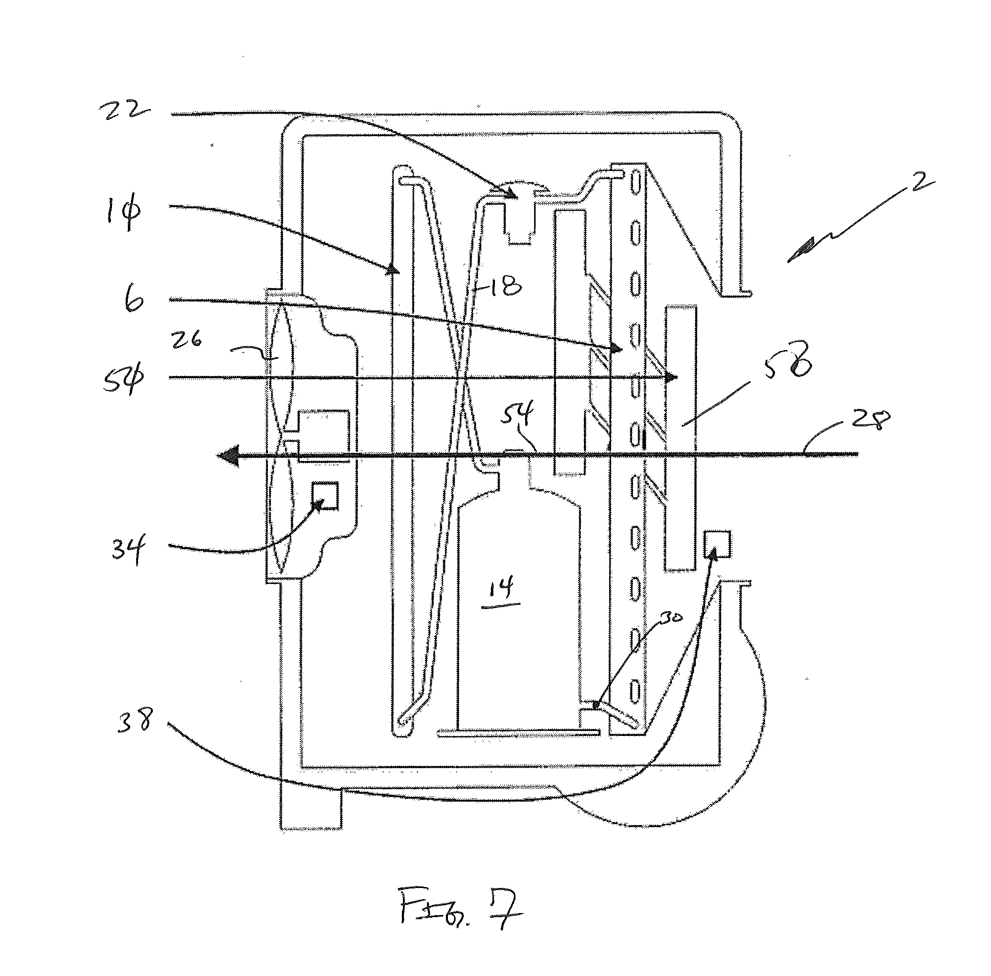
[0030] FIG. 7 is a schematic of a dehumidifier of one embodiment of the present invention that employs a fin/tube evaporator, a micro channel condenser and an evaporator pre-cooler;
[0031] FIG. 8 is a schematic of a dehumidifier of one embodiment of the present invention that employs a fin/tube evaporator, a micro channel condenser and an evaporator pre-cooler;
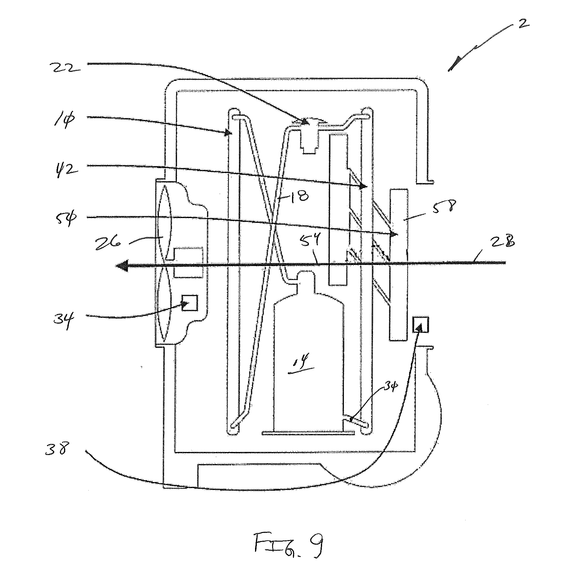
[0032] FIG. 9 is a schematic of a dehumidifier of one embodiment of the present invention that employs a micro channel evaporator, a micro channel condenser and an evaporator pre-cooler;
[0033] FIG. 10 is a schematic of a dehumidifier of one embodiment of the present invention that employs a micro channel evaporator, a micro channel condenser and an evaporator pre-cooler;
[0034] FIG. 11 is a schematic of a dehumidifier of one embodiment of the present invention that employs a fin/tube evaporator, a fin/tube condenser and an evaporator pre-cooler;
[0035] FIG. 12 is a schematic of a dehumidifier of one embodiment of the present invention that employs a fin/tube evaporator, a fin/tube condenser and an evaporator pre-cooler;
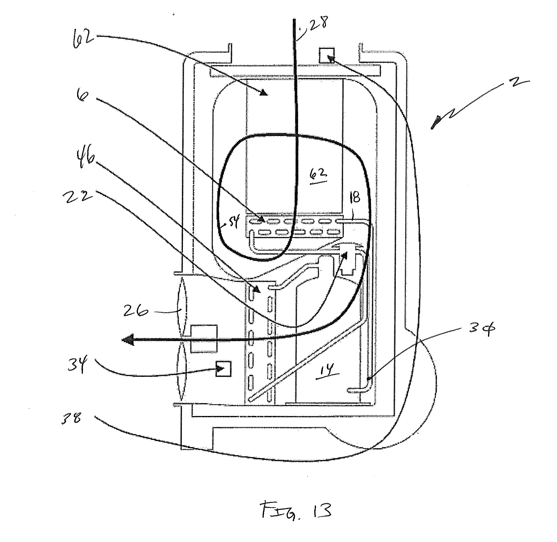
[0036] FIG. 13 is a schematic of a dehumidifier of one embodiment of the present invention that employs a fin/tube evaporator and a fin/tube condenser;
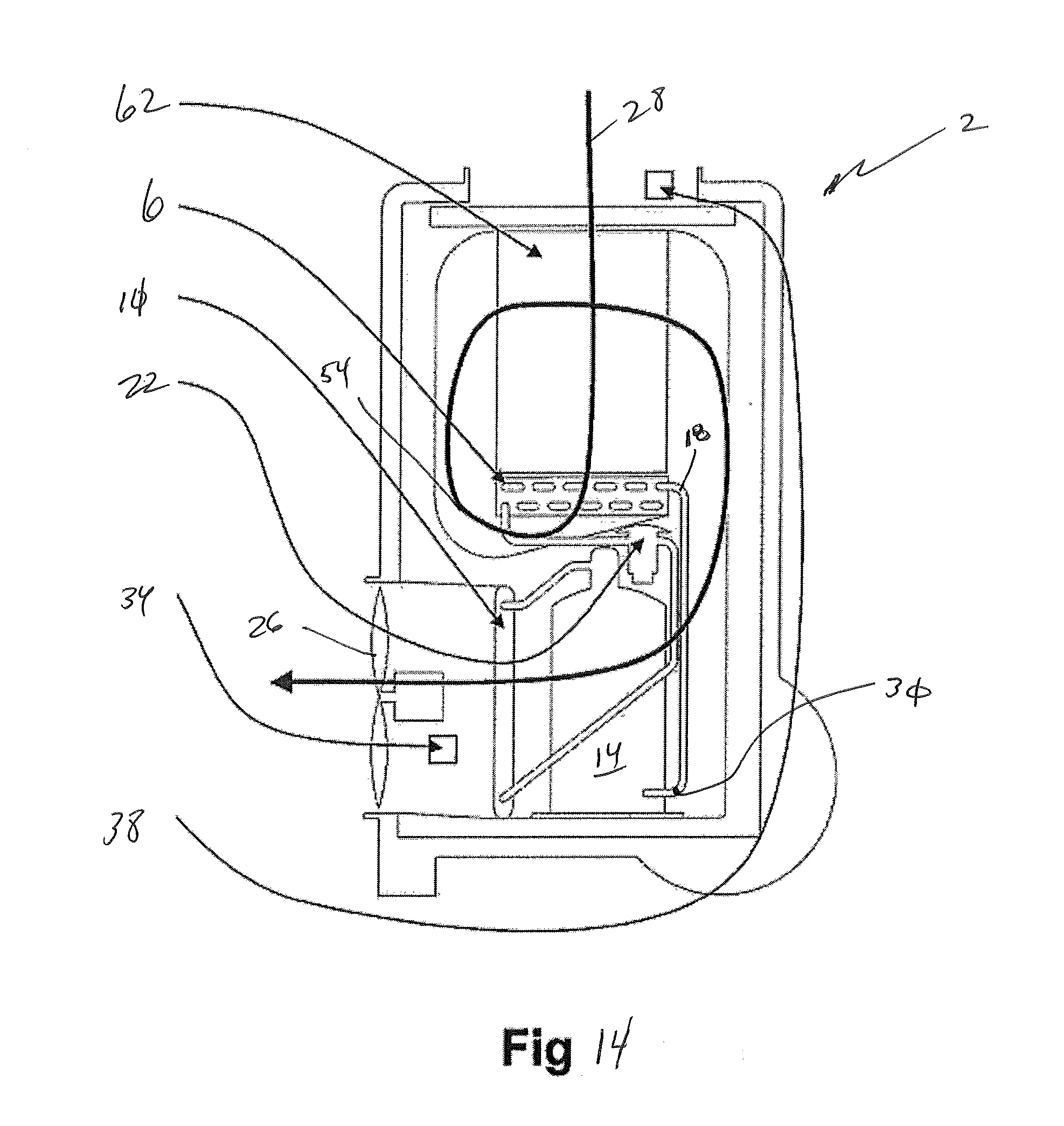
[0037] FIG. 14 is a schematic of a dehumidifier of one embodiment of the present invention that employs a fin/tube evaporator and a micro channel condenser; and
[0038] FIG. 15 is a schematic of a dehumidifier of one embodiment of the present invention that employs a micro channel evaporator and a micro channel condenser.
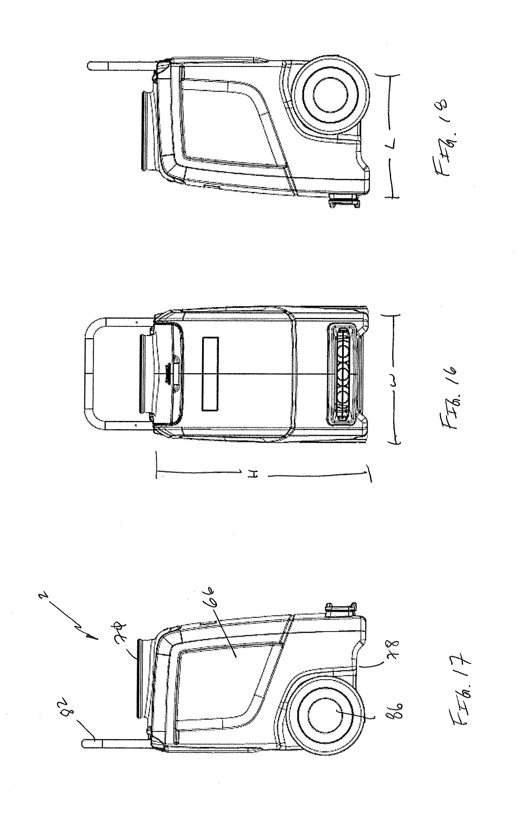
[0039] FIG. 16 is a front elevation view of one embodiment of the present invention;
[0040] FIG. 17 is a left elevation view of FIG. 16;
[0041] FIG. 18 is a right elevation view of FIG. 16;
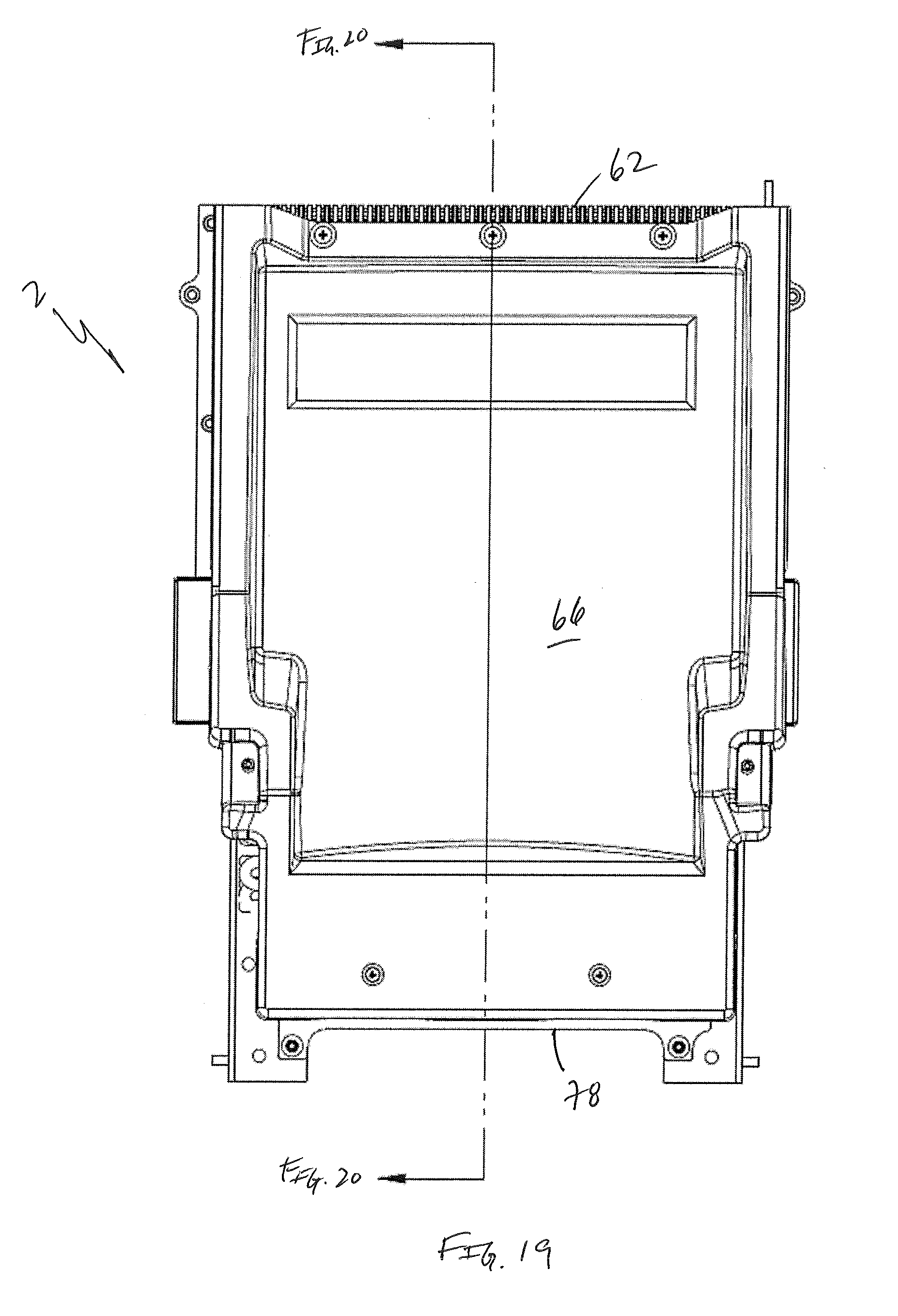
[0042] FIG. 19 is a view of the embodiment shown in FIG. 16 wherein portions of a housing have been removed for clarity;
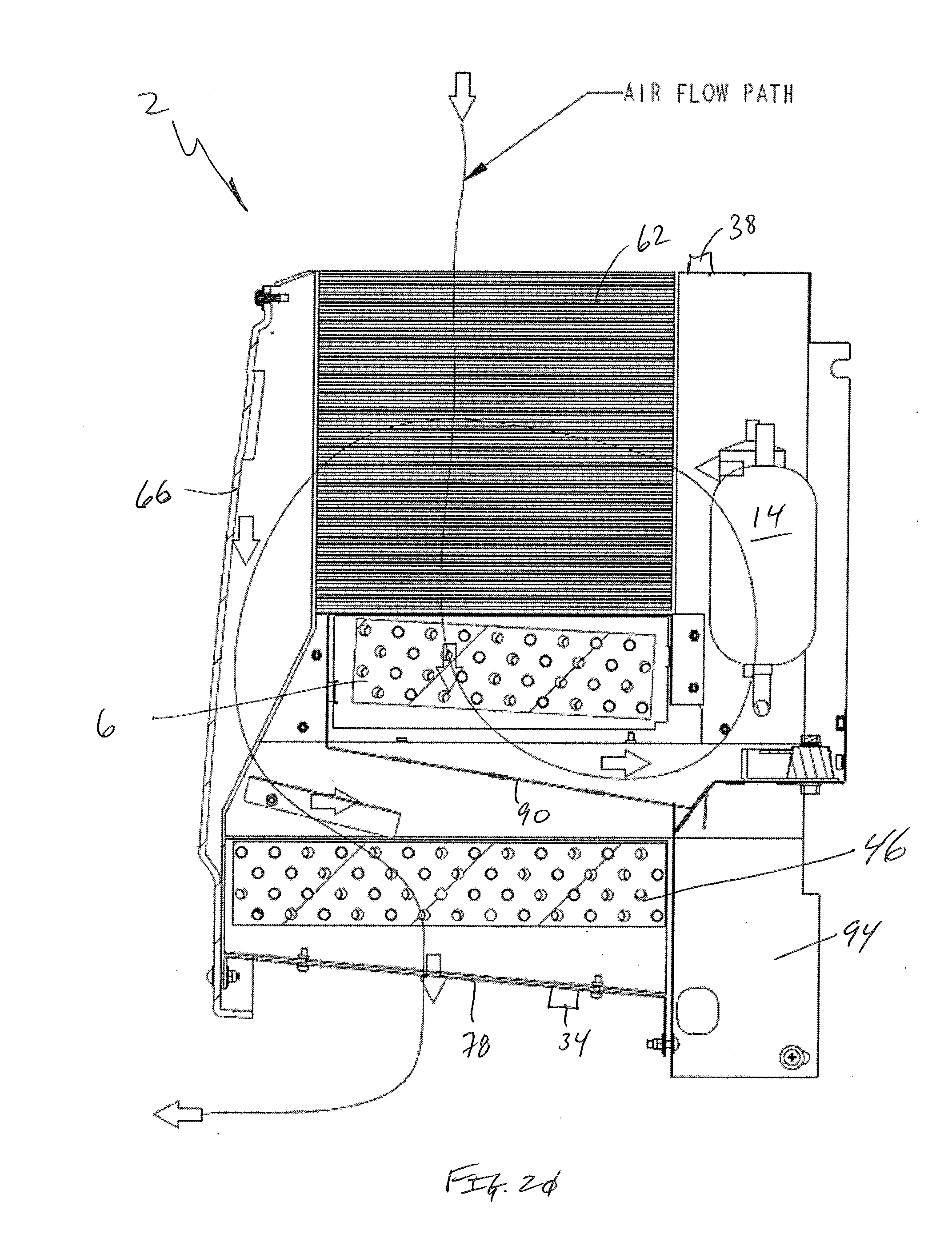
[0043] FIG. 20 is a cross-sectional view of FIG. 19;
[0044] FIG. 21 is a top plan view of FIG. 19;
[0045] FIG. 22 is a simplified perspective exploded view showing the interior components employed by one embodiment of the present invention; and
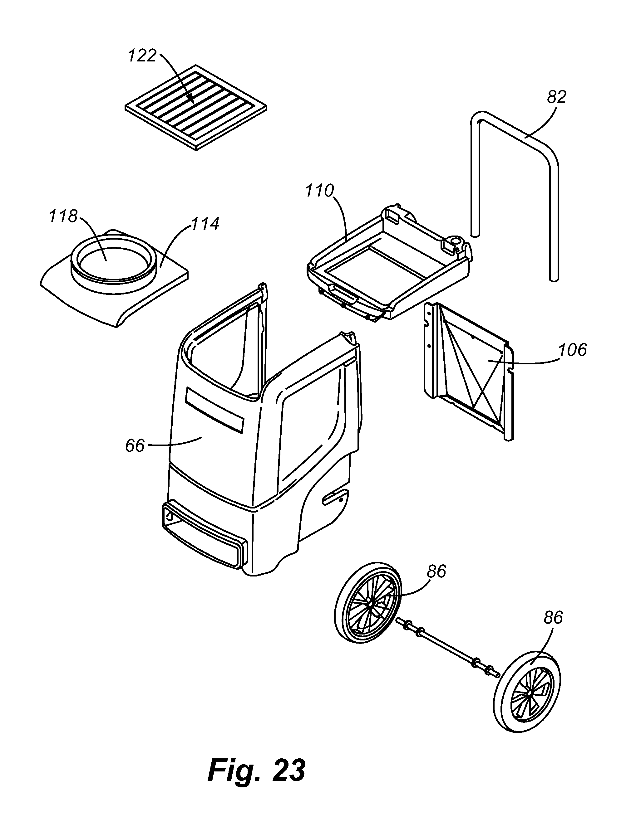
[0046] FIG. 23 is a simplified perspective exploded view of the exterior components employed by embodiments of the present invention.
[0047] To assist in the understanding of one embodiment of the present invention the following list of components and associated numbering found in the drawings is provided herein:
TABLE-US-00001 # Component 2 Dehumidifier 6 Fin/tube evaporator 10 Micro channel condenser 14 Compressor 18 Tubing 22 Thermal Expansion Valve (TEV) 26 Fan 28 Air 30 Evaporator refrigerant exit temperature sensor 34 Exit Temperature and/or humidity sensor 38 Intake temperature and/or humidity sensor 42 Micro channel evaporator 46 Fin/tube condenser 50 Pre-cooler 54 Cooled air 58 Fan 62 Air-to-air heat exchanger 66 Housing 70 Intake 78 Bottom surface 82 Handle 86 Wheel 90 Channel 94 Storage tank 98 Frame 102 Air flow deflector 106 Back plate 110 Cap 114 Lid 118 Aperture 122 Filter
[0048] It should be understood that the drawings are not necessarily to scale. In certain instances, details that are not necessary for an understanding of the invention or that render other details difficult to perceive may have been omitted. It should be understood, of course, that the invention is not necessarily limited to the particular embodiments illustrated herein.
DETAILED DESCRIPTION
[0049] Referring now to FIGS. 1 and 2, one embodiment of the dehumidifier 2 is shown that includes a fin/tube evaporator 6, a micro channel condenser 10, a compressor 14 and related tubing 18 connecting those components. In addition, a thermal expansion valve (TEV) 22 is associated with the tubing 18 that connects the evaporator 6 to the condenser 10.
[0050] In operation, a fan 26 draws air 28 into the dehumidifier 2 wherein warm, humid air passes over the fins and tubes of the evaporator 6. Refrigerant within the evaporator 6 then is heated, exits the evaporator 6, and is directed to the TEV 22. The refrigerant directed to the TEV 22 is of a greater temperature as result of its heat transfer from the intake air. The temperature of the refrigerant exiting the evaporator 6 is related to varying ambient conditions and is monitored by a sensor 30. Warm vaporized refrigerant is directed to the compressor 14 that compresses the refrigerant and directs it to the condenser 10. Air exiting the evaporator 6 is also directed to the condenser 10. The condenser 10, then, turns hot vaporized refrigerant into liquid as cool air from the evaporator 6 picks up heat from the refrigerant. The now cooled refrigerant is directed from the condenser 10 to the TEV 22 to be expanded into low pressure fluid that receives heat from the incoming air. The TEV is associated with a sensor 30 such that it meters the flow of refrigerant to the evaporator 6 based on the exit temperature sensed. More specifically, the higher the temperature expelled by the evaporator 6 the more heat transfer is needed, thus, the flow of refrigerant is increased by the TEV 22. Conversely, the lower the ambient temperature the less heat transfer is needed and flow is reduced by the TEV 22.
[0051] The input sensor 38 and the exit sensor 34 measure temperature and relative humidity of the inlet and exhaust air flow. Data taken from the sensors is fed to a processor/radio (P/R), which employs an internal clock, that also receives information associated with the electrical current (amps) being drawn by the dehumidifier 2. The water level in the storage tank 94 (see FIG. 20) is also monitored. A thermocouple that senses temperature at the evaporator 6 communicates with the P/R.
[0052] The P/R of embodiments of the present invention controls the compressor 14, the condensate pump and the main fan 26. The data collected by the sensors is used to calculate the Grains per Pound (GPP) of the input and output air flow. The data is also used to calculate the performance of the dehumidifier 2, is combined with electrical current used by the dehumidifier 2 to calculate system efficiency, is used to calculate ideal fan 26 speed, is used by the P/R to adjust the fan speed, etc.
[0053] Further, during system shut down, the P/R can run the fan 26 for an extra amount of time to clear the water deposited on the evaporator 6. The condensate pump will also be triggered by the P/R to empty all captured condensate from storage tank 94. The P/R can shut down the machine if it senses the water level in the storage tank 94 is too high.
[0054] In addition, the P/R can shut down the compressor 14, but continue to run the fan 26 if it senses that the evaporator 6 is frozen, which is known as a defrost cycle. During the defrost cycle, the P/R will not turn the compressor 14 on until a threshold temperature is reached, at which time the P/R starts a clock to delay compressor start up to provide extra time for the dehumidifier 2 to fully defrost. This contemplated process eliminates the need for the dehumidifier 2 to cycle on and off due to thawing and re-frosting.
[0055] The P/R may output information to a display located on the dehumidifier's control panel and may output data and information to an operator by way of RF or WiFi transmission. The displayed information may include: input and output temperature and relative humidity of the air flow, current (amps) drawn by the machine, input and output GPP, dehumidifier performance, dehumidifier efficiency, time in defrost mode, visual and audio alarms associated with a storage tank overfill situation, visual and audio alarms associated with overheating or malfunctioning components, and the speed of the fan.
[0056] Referring now to FIGS. 3 and 4, yet another embodiment of the dehumidifier 2 is shown that is similar to that shown in FIG. 1, wherein a micro channel evaporator 42 is employed instead of a fin/tube evaporator.
[0057] Referring now to FIGS. 5 and 6 a dehumidifier 2 of another embodiment of the present invention is shown. This embodiment of the present invention employs a fin/tube condenser 46 along with a fin/tube evaporator 6 and is similar to that shown in FIG. 1.
[0058] Referring now to FIGS. 7 and 8 a dehumidifier 2 that employs a pre-cooler 50 is shown. Here, the fin/tube evaporator 6 receives cooled air 54 from the pre-cooler assembly 50. The pre-cooler assembly 50 includes a series of fins and tubes that pull air with a fan 58 into the fin/tube evaporator 6. The coolant within the fins and tubes of the evaporator 6 is thus, cooler and water 46 is more efficiently collected by the evaporator 6.
[0059] Referring now to FIGS. 9 and 10, yet another embodiment of the present invention that employs a pre-cooler 50 is shown. This embodiment is similar to that shown in FIG. 7 wherein a micro channel evaporator is employed.
[0060] Referring now to FIGS. 11 and 12, another embodiment of the present invention is provided that employs a pre-cooler 50 that is similar to that described above with reference to FIGS. 4 and 5. The dehumidifier 2 shown employs a fin/tube condenser 46 and fin/tube evaporator 6.
[0061] Referring now to FIG. 13, another dehumidifier 2 that employs a pre-cooler of an alternator configuration is shown. Here, the fin/tube evaporator 6 receives air 54 from an air-to-air heat exchanger assembly 62. The air-to-air heat exchanger assembly 62 includes a series of plates connected at alternating ends to allow air to flow in two directions (vertical and horizontal). The incoming air 28 is cooled via convective methods by the air exiting the evaporator 6.
[0062] Referring now to FIG. 14, yet another embodiment of the present invention that employs an air-to-air heat exchanger 62. This embodiment is similar to that shown in FIG. 13, but employs a micro channel condenser 10.
[0063] Referring now to FIG. 15 another embodiment of the present invention is provided that employs an air-to-air pre-cooler 62. The dehumidifier 2 shown employs a micro channel condenser 10 and a micro channel evaporator 46.
[0064] FIGS. 16-18 show one embodiment of the present invention that employs a housing 66 that encloses the internal components. The housing 66 employs an intake 70 that receives air and an exhaust that expels dryer air from a bottom surface 78 of the dehumidifier 2. In order to facilitate movement of the dehumidifier 2, a handle 82 and at least two wheels 86 are provided. Embodiments of the present invention are about 341/2 inches tall (H), 201/2 inches wide (W) and about 23 inches long (L).
[0065] Referring now to FIGS. 19-21, the arrangement of the internal components of one embodiment of the present invention is shown. Air 28 is received within the dehumidifier 2 through the heat exchanger 62 that cools the incoming air. The cooled air is then introduced to the evaporator 6, which further cools the air by heat transfer to the cold fluid running therethrough. Although a fin/tube evaporator 6 is shown, one of skill in the art will appreciate that a micro channel evaporator may be employed. The cooling of the humid air condenses trapped water on the evaporator that drips from the evaporator 6 onto a channel 90 that leads to a storage tank 94. The drier air is directed across a condenser 46 as described above and exits out from the bottom surface 78 of the dehumidifier 2. Although a fin/tube condenser 46 is shown, one of skill in the art will appreciate that a micro channel condenser may be employed. The storage tank 94 of one embodiment of the present invention is removable to facilitate emptying. Further, as described above, it is contemplated that pumps that are used to circulate refrigerant through the evaporator 6 and the condenser 46 run for a time after the dehumidifier 2 is turned off so as to ensure that all of the water collected by the evaporator 6 is transferred to the storage tank 94. As can be ascertained by the arrows presented on the drawing, the housing 66 acts to channel air through the heat exchanger 62 and other components.
[0066] FIG. 22 shows an interior component arrangement employed by one embodiment of the present invention. Here, a frame 98 is employed that secures an air flow deflector 102, condenser 46, the evaporator 6, the compressor 14 and air to air heat exchanger 42. The housing 66 envelops the components and ensures proper air flow through the evaporator 6 and the condenser 46. In order to facilitate such air flow, the air flow deflector 102 may be employed.
[0067] Referring now to FIG. 23, the housing 66 and associated components are shown. Here, the housing 66 is a generally three sided structure that cooperates with a back plate 106 to create an air channel. The housing is sealed with a cap 110 and a lid 114. The lid 114 has an aperture 118 for receiving humid air that is directed into the internal components of the dehumidifier. Some embodiments of the present invention employ an inlet filter 122 between the lid 114 and the cap 110 to ensure that particulate matter does not impede air flow through the heat exchanger or other components. As mentioned above, the dehumidifier is easily moved as it is associated with at least two wheels 86 and a handle 82.
[0068] While various embodiments of the present invention have been described in detail, it is apparent that modifications and alterations of those embodiments will occur to those skilled in the art. However, it is to be expressly understood that such modifications and alterations are within the scope and spirit of the present invention, as set forth in the following claims. Further, the invention(s) described herein is capable of other embodiments and of being practiced or of being carried out in various ways. In addition, it is to be understood that the phraseology and terminology used herein is for the purpose of description and should not be regarded as limiting. The use of "including," "comprising," or "having" and variations thereof herein is meant to encompass the items listed thereafter and equivalents thereof as well as additional items.
* * * * *
References
D00000
D00001
D00002
D00003
D00004
D00005
D00006
D00007
D00008
D00009
D00010
D00011
D00012

D00013
D00014
D00015

D00016
D00017
D00018
D00019

D00020

D00021
XML
uspto.report is an independent third-party trademark research tool that is not affiliated, endorsed, or sponsored by the United States Patent and Trademark Office (USPTO) or any other governmental organization. The information provided by uspto.report is based on publicly available data at the time of writing and is intended for informational purposes only.
While we strive to provide accurate and up-to-date information, we do not guarantee the accuracy, completeness, reliability, or suitability of the information displayed on this site. The use of this site is at your own risk. Any reliance you place on such information is therefore strictly at your own risk.
All official trademark data, including owner information, should be verified by visiting the official USPTO website at www.uspto.gov. This site is not intended to replace professional legal advice and should not be used as a substitute for consulting with a legal professional who is knowledgeable about trademark law.