Cooling, Heating And Power System With An Integrated Part-load, Active, Redundant Chiller
Rog; Lynn M. ; et al.
U.S. patent application number 12/735662 was filed with the patent office on 2010-12-30 for cooling, heating and power system with an integrated part-load, active, redundant chiller. Invention is credited to Lynn M. Rog, James Eric Vanderpas, Timothy C. Wagner, Kevin Wyman.
| Application Number | 20100326098 12/735662 |
| Document ID | / |
| Family ID | 41065725 |
| Filed Date | 2010-12-30 |
| United States Patent Application | 20100326098 |
| Kind Code | A1 |
| Rog; Lynn M. ; et al. | December 30, 2010 |
COOLING, HEATING AND POWER SYSTEM WITH AN INTEGRATED PART-LOAD, ACTIVE, REDUNDANT CHILLER
Abstract
A cooling, heating and power system (10) includes a prime mover (12) for producing electricity having a thermal output (18) and an electrical output (20) coupled to an absorption chiller (24). A part-load, active, redundant chiller (26) is thermally coupled to the absorption chiller (24) for receiving a cooling-heating fluid from the absorption chiller (24). The part-load chiller (26) operates at maximum efficiency at between about forty percent and about sixty percent of a maximum cooling load of the chiller (26) to thereby generate large volumes of cooling very efficiently. The system (10) may direct the cooling into a multi-zone cooling-heating circuit (40) including a critical zone (42) and a utility zone (44) thermally coupled to the chiller (26) for selectively delivering the cooling-heating fluid to at least one of the critical zone (42) and the utility zone (44) of the circuit (40).
| Inventors: | Rog; Lynn M.; (South Windsor, CT) ; Wyman; Kevin; (West Hartford, CT) ; Wagner; Timothy C.; (East Hartford, CT) ; Vanderpas; James Eric; (Sparta, NJ) |
| Correspondence Address: |
    Malcolm J. Chisholm
    P.O. Box  278
    Lee
    MA
    01238
    US
|
| Family ID: | 41065725 |
| Appl. No.: | 12/735662 |
| Filed: | March 12, 2009 |
| PCT Filed: | March 12, 2009 |
| PCT NO: | PCT/US2009/001584 |
| 371 Date: | August 5, 2010 |
Related U.S. Patent Documents
| Application Number | Filing Date | Patent Number | ||
|---|---|---|---|---|
| 61069276 | Mar 12, 2008 | |||
| Current U.S. Class: | 62/101 ; 62/476 |
| Current CPC Class: | F25B 2500/06 20130101; F25B 27/00 20130101; F25B 25/00 20130101 |
| Class at Publication: | 62/101 ; 62/476 |
| International Class: | F25B 15/00 20060101 F25B015/00 |
Claims
1. A cooling, heating and power system (10), the system (10) comprising: a. a prime mover (12) for producing electricity having a thermal output (18) and an electrical output (20); b. an absorption chiller (24) thermally coupled to the thermal output (18) and electrically coupled to the electrical output (20) of the prime mover (12) for receiving heat and electricity from the prime mover (12); c. a part-load, active, redundant chiller (24) electrically coupled to the prime mover (12) for receiving electricity from the prime mover (12), and thermally coupled to the absorption chiller (24) for receiving a cooling-heating fluid from the absorption chiller (24); and, d. wherein the part-load, active, redundant chiller (26) operates at maximum efficiency at between about forty percent and about sixty percent of a maximum cooling capacity of the chiller (26).
2. The system (10) of claim 1, further comprising a system controller (74) for controlling the absorption chiller (24) to utilize a maximum amount of thermal energy generated by the prime mover (12) while simultaneously controlling the part-load, active, redundant chiller (26) to operate at maximum efficiency at between about forty percent and about sixty percent of the maximum cooling capacity of the chiller (26).
3. The system (10) of claim 1, wherein the part-load, active, redundant chiller (26) is secured in electrical communication with the prime mover (12) and with an exterior source (34) of electricity not generated by the prime mover (12).
4. The system (10) of claim 1, further comprising a multi-zone cooling-heating circuit (40) including a critical zone (42) and a utility zone (44) thermally coupled to the part-load, active, redundant chiller (26) through a circuit feed line (46) for directing the cooling-heating fluid into the circuit (40) and by way of a circuit pump (49) through a circuit return line (48) for returning the fluid to the absorption chiller (24), and wherein the multi-zone cooling-heating circuit (40) is configured for selectively delivering the cooling-heating fluid from the active, redundant chiller (26) to at least one of the critical zone (42) and the utility zone (44) of the circuit (40).
5. The system (10) of claim 4, further comprising a circuit control valve (54) for selectively delivering the cooling-heating fluid from the active, redundant chiller (26) to at least one of the critical zone (42) and the utility zone (44) of the circuit (40).
6. The system (10) of claim 4, wherein the circuit (40) is configured for directing flow of the cooling-heating fluid from the at least one of the critical zone (42) and the utility zone (44) back through the circuit return line (48) to at least one of the absorption chiller (24) and the part-load, active, redundant chiller (26).
7. The system (10) of claim 4, further comprising an absorption chiller by-pass line (52) secured in fluid communication between a by-pass valve (50) upstream of the absorption chiller (24) and the part-load, active, redundant chiller (26), for selectively directing the cooling-heating fluid returning from the cooling-heating circuit (40) around the absorption chiller (24).
8. The system (10) of claim 4, further comprising a part-load, active, redundant chiller (26) by-pass line (70) in fluid communication with a part-load, active, redundant chiller (26) by-pass valve (72) secured in fluid communication between the absorption chiller (24), and the circuit feed line (46) for selectively directing the cooling-heating fluid to by-pass the part-load, active, redundant chiller (26).
9. A method for providing cooling, heating and power, the method comprising: a. directing recoverable waste heat from a prime mover (12) into an absorption chiller (12); b. utilizing the waste heat within the absorption chiller (24) to support operation of the absorption chiller (24); c. directing flow of a cooling-heating fluid through the absorption chiller (24) to cool the cooling-heating fluid; d. controlling operation of the absorption chiller (24) at about maximum cooling capacity of the absorption chiller (24) while the cooling-heating fluid flows through the absorption chiller (24); e. then, directing flow of the cooling-heating fluid through a part-load, active, redundant chiller (26) to further cool the, cooling-heating fluid; and, f. operating the part-load, active, redundant chiller (26) at between about forty percent and about sixty percent of a maximum cooling load of the chiller (26).
10. The method of claim 9, further comprising controlling the absorption chiller (24) to utilize a maximum amount of thermal energy generated by the prime mover (12) while simultaneously controlling the part-load, active, redundant chiller (26) to operate at maximum efficiency at between about forty percent and about sixty percent of the maximum cooling capacity of the chiller (26).
11. The method of claim 9, further comprising selectively directing flow of the cooling-heating fluid leaving the part-load, active, redundant chiller (26) into at least one of a critical zone (42) and a utility zone (44) of a multi-zone cooling-heating circuit (40) secured in fluid communication with the chiller (26).
12. The method of claim 10, further comprising selectively directing flow of the cooling-heating fluid from a circuit return line (48) to by-pass the absorption chiller (24) by directing flow of the cooling-heating fluid through an absorption chiller by-pass line (52) secured in fluid communication between a by-pass valve (50) upstream of the absorption chiller (24) and the part-load, active, redundant chiller (26).
13. A method of delivering cooling to a multi-zone cooling-heating circuit (40) having a critical zone (42) and a utility zone (44), the method comprising: a. generating electricity and recoverable waste heat within a prime mover (12); b. directing flow of the generated waste heat into an absorption chiller (24); c. cooling a cooling-heating fluid circulating through the multi-zone cooling-heating circuit (40) by flowing the cooling-heating fluid through the absorption chiller (24); d. further cooling the cooling-heating fluid by then directing flow of the fluid through a part-load, active, redundant chiller (26); and, e. selectively directing flow of the cooled, circulating cooling-heating fluid into at least one of the critical zone (42) and the utility zone (44).
14. The method of claim 13, further comprising controlling the absorption chiller (24) to utilize a maximum amount of waste heat generated by the prime mover (12) while simultaneously controlling the part-load, active, redundant chiller (26) to operate at maximum efficiency at between about forty percent and about sixty percent of a maximum cooling capacity of the chiller (26).
15. The method of claim 13, further comprising operating at peak cooling by controlling the absorption chiller (24) to utilize a maximum amount of waste heat generated by the prime mover (12) while simultaneously controlling the part-load, active, redundant chiller (26) to operate at between about ninety percent and about one-hundred percent of a maximum cooling capacity of the chiller (26), and directing flow of as much cooling from the chiller (26) into the critical zone (42) as is necessary to satisfy cooling requirements of the critical zone (42).
16. The method of claim 13, further comprising operating at offnormal cooling whenever operation of the absorption chiller (24) is interrupted by controlling the part-load, active, redundant chiller (26) to operate at between about ninety percent and about one-hundred percent of a maximum cooling capacity of the chiller (26), and by directing flow of as much cooling from the chiller (26) into the critical zone (42) as is necessary to satisfy cooling requirements of the critical zone (42).
17. The method of claim 13, further comprising operating at offnormal cooling whenever operation of the prime mover (12) is interrupted by directing flow of electricity into the part-load, active, redundant chiller (26) from an exterior source (34) of electricity; by controlling the part-load, active, redundant chiller (26) to operate at between about ninety percent and about one-hundred percent of a maximum cooling capacity of the chiller (26); and, by directing flow of as much cooling from the chiller (26) into the critical zone (42) as is necessary to satisfy cooling requirements of the critical zone (42).
Description
CROSS REFERENCE TO RELATED APPLICATION
[0001] This Application claims the benefit of U.S. Provisional Patent Application Ser. No. 61/069,276 that was filed on Mar. 12, 2008, entitled "Redundant Cooling Integrated with CHP".
TECHNICAL FIELD
[0002] The present disclosure relates generally to use of cooling, heating and power systems (occasionally referred to as "CHP", or "CCHP" for "combined cooling, heating and power") that include a prime mover for producing electrical and/or mechanical energy that is thermally and electrically coupled with an absorption chiller for producing cooling and heating for such things as buildings having data centers, hospitals, etc. More particularly, the disclosure includes such a CHP system with an integrated part-load, active, redundant electric chiller and a system controller to provide more efficient cooling with a capacity for more efficient peak and back up cooling capacity.
BACKGROUND ART
[0003] Providing cooling, heating and power to modern structures such as buildings, oil drilling platforms, etc., increasingly requires sensitivity to supplying adequate cooling to critical zones of the structure. The critical zone most often includes data centers having large computers, servers, etc. that generate a lot of heat, wherein the heat must be removed from the data center to support acceptable operation of the data apparatus therein. Other heat sensitive, critical zones include hospital operating rooms and intensive care units, refrigerated food processing centers, etc. It is known to separate a supply of cooling, heating and power to such critical zones from the supply of cooling, heating and power to other less critical areas of the structure, referred to herein for convenience as a "utility zone". In the event of an interruption of a supply of power from an exterior source of electricity (e.g., the "grid"), modern structures invariably include a backup electricity supply to operate cooling chillers, heaters, and to supply electrical power until the grid supply is returned. To minimize the cost and complexity of such a backup system, it is known for enhanced security of cooling, heating and power supply to have the backup CHP source prioritize delivery of cooling, heating and power to only the critical zone, or to satisfy all of the needs of the critical zone and to supply any excess cooling, heating and/or power to an adjoining utility zone.
[0004] An exemplary cooling, heating and power system includes as a prime mover a one or more energy producing apparatus powered by natural gas, wherein the energy producing apparatus power electrical generators for supplying electricity to a structure. (For purposes herein, the phrase "prime mover" is to mean any energy production apparatus, including a diesel generator, microturbine(s), a fuel cell(s), etc., that produces electrical energy and recoverable waste heat.) Waste heat (e.g., hot exhaust gas from the energy production apparatus) is directed to flow into an absorption chiller to minimize power necessary to run the chiller. Electricity is also directed from the prime mover to the absorption chiller. The absorption chiller generates cooling and heating that can be directed through thermal coupling into a structure to remove heat from a data center, and to otherwise cool and heat the structure depending upon demands of the structure.
[0005] Such a prime mover combined with an absorption chiller is therefore a cooling, heating and power (CHP) system. Absorption chillers are well known, such as disclosed in U.S. Pat. Nos. 7,065,976 and 7,273,071, both of which Patents are owned by the owner of all rights in the present disclosure. A known CHP system is available under the brand name "PureComfort Power Solution" from UTC POWER, LLC of South Windsor, Conn., U.S.A. ("PureComfort" is a registered trademark of UTC POWER, LLC.) An ordinary installation of such a CHP system is for the system to be wired in parallel with an exterior grid supply of electricity. During normal operation, the CHP system, using natural gas, supplements the cooling, heating and power requirements of an entire structure, thereby saving energy and reducing dependency on the cost of grid supplied electricity, and providing a more environmentally friendly energy supply than the grid supply which depends largely upon coal and oil generated electricity.
[0006] Existing electrical chillers operate under a range of operating efficiencies. These efficiencies are impacted by the type of vapor compression (centrifugal, screw, rotary scroll compressors, etc.), the type of refrigerant (R-22, R-134a, R123, R410, etc.) and the type of heat rejection (air-cooled or water-cooled). Typical efficiencies for full load chillers operating such as those that typically service critical data services range from 0.45 kilowatt per refrigeration ton ("kW/RT") to 0.90 kW/RT. It is known in the industry to have both ambient relief on the heat rejection that favorably impacts efficiency. Operating the units at less than full load impacts efficiency as well.
[0007] In the event of an interruption of grid supplied electricity, the CHP system would continue to operate while control switches and valves would then direct adequate supplies of cooling, heating and/or power from the CHP system to a critical zone of the structure, such as a data center to ensure ongoing, uninterrupted operation of the data apparatus, etc. Depending upon the nature of the structure supported by the CHP system and the nature of the grid interruption, alternative backup (e.g., diesel generators, etc.) may also be activated to further support the critical and utility zones of the structure. Whenever the grid supply is returned, the CHP system would be controlled to supplement the normal operating total supply of cooling, heating and power to the structure.
[0008] Such a CHP system provides satisfactory supplemental and backup supplies of cooling, heating and electrical power especially to structures having a substantial critical zone, such as banks having data centers that process credit card transactions, switching centers of large communication networks, hospital operating rooms, elevators, etc. A CHP system with a prime mover that is electrically and thermally coupled to an absorption chiller nonetheless gives rise to substantial concerns. For example, if operation of the absorption chiller was interrupted due to a mechanical failure, supply of additional cooling would have to be supplied to the critical zone from an alternative chiller(s).
[0009] Alternatively if operation of the prime mover was interrupted, the absorption chiller depending upon the waste heat from the prime mover, would then also be unable to operate, again requiring the overall cooling supply of the structure to include alternative backup cooling sources. Additionally, the absorption chiller must be dimensioned to satisfy demands of the critical zone during periods of a peak load on the CHP system. For example, during a heat wave in a metropolitan area, it is known that a grid supply may suffer "brown-outs" while cooling demand is at an absolute peak due to the heat wave. Design of a CHP system to satisfy such a circumstance mandates that the absorption chiller be uneconomically sized to perform occasionally at outputs substantially beyond normal load operations. This adds further cost and complexity to the CHP system and to an overall system that provides all of the cooling, heating and power demands of the structure.
[0010] Consequently, there is a need for a cooling, heating and power system that resolves these and related concerns.
SUMMARY
[0011] The disclosure is directed to a cooling, heating and power system that includes a prime mover for producing electricity that has a thermal output and an electrical output. An absorption chiller for producing cooling and heating is thermally coupled and electrically coupled to the thermal output and the electrical output of the prime mover for receiving heat and electricity from the prime mover. A part-load, active, redundant chiller is electrically coupled to the prime mover for receiving electricity from the prime mover, and is also thermally coupled to the absorption chiller for receiving a cooling-heating fluid from the absorption chiller. A "part-load, active, redundant chiller" consists of a chiller that operates most efficiently at part load, such as between about forty percent ("40%") and about 60% of a maximum cooling load.
[0012] By integrating the part-load, active redundant chiller to operate downstream from the absorption chiller so that it receives the cooling-heating fluid after it has been cooled by the absorption chiller, the part-load, active redundant chiller may operate at a very high rate of efficiency compared to the part-load, active, redundant chiller operating alone to achieve a required decrease in temperature of the cooling-heating fluid. For example, if the circulating cooling-heating fluid must be reduced in temperature by a total of 10 degrees by the cooling, heating and power system, and the absorption chiller first reduces the temperature by 5 degrees, the part-load, active, redundant chiller can be sized to reduce the cooling-heating fluid the additional 5 degrees while operating at between about 40% to about 60% of its capacity or "load", which is a highest efficiency operating point of the part-load, active, redundant chiller. (For purposes herein, the word "about" is to mean plus or minus 10%.) This permits the part-load, active, redundant chiller to operate at a very high rate of efficiency by reducing mechanical work required by the part-load, active, redundant chiller. Then, if operation of the absorption chiller is interrupted, the part-load, active, redundant chiller may be controlled to operate at about one-hundred percent load to satisfy the cooling demands of the critical zone. More importantly, during normal operation of the system, by having the electrically powered part-load, active, redundant chiller operate downstream from the absorption chiller, both chillers may be sized for minimal cost and maximum operating efficiency to thereby deliver cooling to the multi-zone cooling-heating circuit at a very low kilowatt per refrigeration ton ("kW/ton") value, while providing enhanced cooling backup. In a preferred embodiment, the part-load, active, redundant chiller is a high efficiency, tri-screw electric chiller.
[0013] Integrating the part-load, active, redundant chiller downstream from the absorption chiller also permits efficient sizing of the absorption chiller so that the absorption chiller does not have to be substantially over sized beyond normal load conditions to meet peak loads described above. Instead, the part-load, active, redundant chiller is dimensioned to be responsive to normal loads on the system while operating at between about 40% to about 60% load, and during peak load conditions, the part-load, active, redundant chiller is controlled to increase cooling capacity to meet the peak load conditions. If operation of the absorption chiller is interrupted producing offnormal load conditions, the part-load, active, redundant chiller may be controlled to increase its cooling capacity from the efficient 40% to 60% load to a load between about 60% and 100% to meet the offnormal condition. Integration of the part-load, active, redundant chiller with the absorption chiller and prime mover therefore provides enormous efficiencies in manufacture, cost and operation of the cooling, heating and power system of the present disclosure.
[0014] The system may also include a multi-zone cooling-heating circuit including a critical zone and a utility zone. The circuit is thermally coupled to the part-load, active, redundant chiller through a circuit feed line for directing the cooling-heating fluid into the circuit and through a circuit return line for returning the fluid to one of the absorption chiller and the part-load, active, redundant chiller. The multi-zone cooling-heating circuit includes a circuit control valve on the circuit feed line configured for selectively delivering the cooling-heating fluid from the part-load, active, redundant chiller to at least one of the critical zone and the utility zone of the circuit. The circuit is also configured for directing flow of the cooling-heating fluid from the at least one of the critical zone and the utility zone back through the circuit return line to at least one of the absorption chiller and the part-load, active, redundant chiller.
[0015] By integrating the part-load, active, redundant chiller with the prime mover and the absorption chiller, in the event operation of the absorption chiller is interrupted, the cooling-heating fluid would continue to flow into the part-load, active, redundant chiller to be chilled, and the circuit control valve would be controlled to direct the cooling-heating fluid from the part-load, active, redundant chiller only into the critical zone of the multi-zone cooling-heating circuit. Alternatively, the circuit control valve would be controlled to direct as much of the cooling-heating fluid into the critical zone as is necessary to satisfy cooling needs of the critical zone, while the remaining fluid is directed into the utility zone. The multi-zone cooling-heating circuit directs the cooling-heating fluid back from the critical zone and optionally some fluid from the utility zone through the circuit return line into either the non-operational absorption chiller to flow through the absorption chiller, or through an absorption chiller by-pass line directly into the part-load, active, redundant chiller to be cooled again and to continue circulating through the critical zone. Use of the part-load, active, redundant chiller, therefore minimizes any need for any further cooling backup for the critical zone while the absorption chiller is being repaired, replaced, etc.
[0016] In the event operation of the prime mover is interrupted which would terminate the thermal flow from the prime mover into the absorption chiller thereby disrupting operation of the absorption chiller, the part-load, active, redundant chiller may continue to operate while receiving electricity from an alternative source outside of the cooling, heating and power source, such as the external grid supply of electricity. In such an event, the circuit control valve of the multi-zone cooling-heating circuit would direct flow of the cooling-heating fluid into the critical zone as described above.
[0017] A primary use of the cooling, heating and power system with an integrated part-load, active, redundant chiller is to substantially decrease overall cooling costs as well as to supplement, secure and backup the cooling, heating and power requirements of a structure, such as a building having a critical zone and a utility zone. It is to be understood that the present disclosure may also be utilized as a stand alone cooling, heating and power system without parallel electricity supplied by the grid, such as to be the primary cooling, heating and power system for an oil drilling platform or for similar stand alone usages. The cooling, heating and power system of the present disclosure also provides the above described advantages in such usages.
[0018] Accordingly, it is a general purpose of the present disclosure to provide a cooling, heating and power system with an integrated part-load, active, redundant chiller that overcomes deficiencies of the prior art.
[0019] It is a more specific purpose to provide a cooling, heating and power system with an integrated part-load, active, redundant chiller that increases operating efficiencies of the system and decreases manufacture, installation and operational costs of the system.
[0020] These and other purposes and advantages of the present cooling, heating and power system with an integrated part-load, active, redundant chiller will become more readily apparent when the following description is read in conjunction with the accompanying drawing.
BRIEF DESCRIPTION OF DRAWING
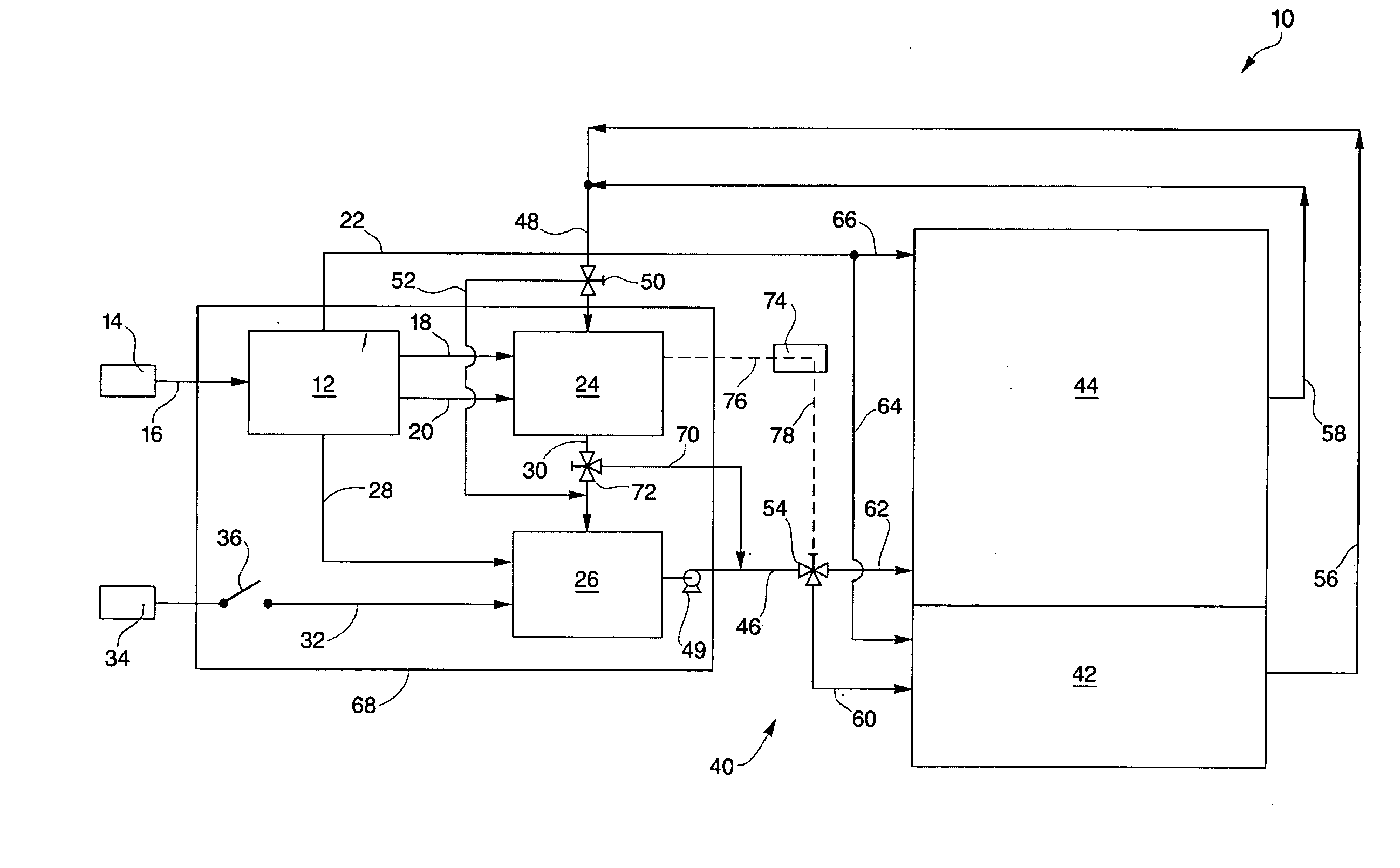
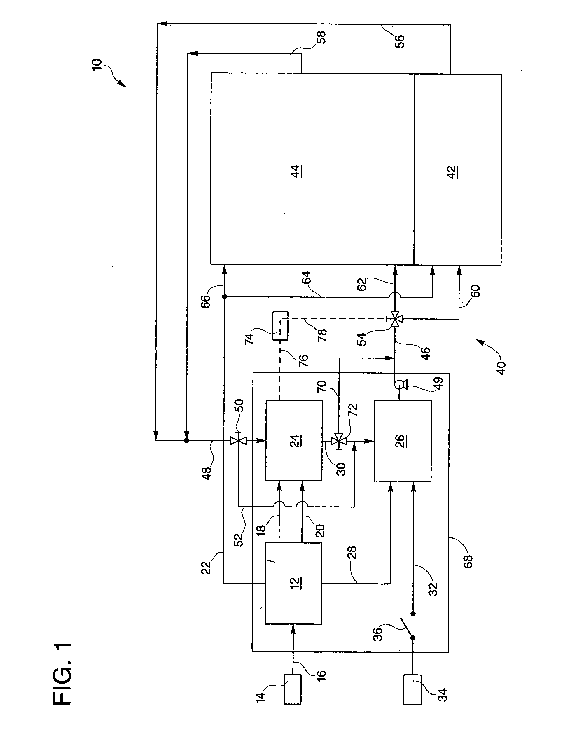
[0021] FIG. 1 is a simplified schematic representation of a cooling, heating and power system with an integrated part-load, active, redundant chiller of the present disclosure.
DESCRIPTION OF THE PREFERRED EMBODIMENTS
[0022] Referring to the drawings in detail, a cooling, heating and power system with an integrated part-load, active, redundant chiller of the present disclosure is generally designated by the reference numeral 10. The system 10 includes a prime mover 12 that receives fuel, such as natural gas, from a fuel source 14 through a fuel inlet line 16 to produce electricity. The prime mover 12 may be any apparatus capable of producing electricity, such as a microturbine(s) mechanically coupled to an electric generator(s), a diesel or gas engine, a fuel cell, etc., and that also generates waste heat. The primer mover 12 also includes a thermal output 18 and an electrical output 20, and may also include a primary electrical line 22 for delivering additional electricity produced by the prime mover 12.
[0023] The system also includes an absorption chiller 24 for producing cooling and heating and the absorption chiller 24 is thermally coupled and electrically coupled to the thermal output 18 and the electrical output 20 of the prime mover 12 for receiving heat and electricity from the prime mover 12. A part-load, active, redundant chiller 26 (also referred to occasionally herein for convenience as an "ARC") is electrically coupled through an ARC prime mover electric feed line 28 to the prime mover 12 for receiving electricity from the prime mover 12. The "part-load, active, redundant chiller" 26 consists of a chiller that operates most efficiently at part load, such as between about forty percent ("40%") and about 60% or a maximum load. The part-load, active redundant chiller 26 is also thermally coupled through an ARC thermal feed line 30 to the absorption chiller 26 for receiving a cooling-heating fluid from the absorption chiller 26. An exterior electric feed line 32 may also be included in the system 10 to direct electricity from an exterior source 34 such as the electric grid to the part-load, active, redundant chiller 26 through an exterior feed line switch 36 on feed line 32. Preferably, the part-load, active, redundant chiller 26 is plumbed to the absorption chiller in a side streaming arrangement.
[0024] The cooling, heating and power system 10 of the present disclosure may also include a multi-zone cooling-heating circuit 40 including a critical zone 42, and a utility zone 44. The multi-zone cooling-heating circuit 40 may be installed in a structure, such as a building (not shown), and in such an installation, the critical zone 42 could include a data center (not shown), while the utility zone 44 could include other areas (not shown) of the building, such as offices, meeting rooms, hallways, manufacturing or processing rooms, a warehouse, etc. The multi-zone heating-cooling circuit 40 is thermally coupled to the part-load, active, redundant chiller 26 through a circuit feed line 46 for directing the cooling-heating fluid into the circuit 40 and through a circuit return line 48 for returning the cooling-heating fluid to one of the absorption chiller 24 and the part-load, active, redundant chiller 26. The circuit 40 may also include a circuit pump 49 secured in fluid communication with the circuit 40, such as with the circuit feed line 46, to circulate the cooling-heating fluid through the circuit 40. The circuit return line 48 may include an absorption chiller by-pass valve 50 and an absorption chiller by-pass line 52 secured in fluid communication between the by-pass valve 50 upstream of the absorption chiller 24 and the part-load, active, redundant chiller 26, to selectively direct cooling-heating fluid returning from the cooling-heating circuit 40 around the absorption chiller 24. It may be desirable for the cooling-heating fluid to bypass the absorption chiller 24 such as when the chiller 24 is not operating. (For purposes herein, the word "selectively" is to mean that a particular component may be controlled or "selected" to perform two or more functions.)
[0025] The multi-zone cooling-heating circuit 40 also includes a circuit control valve 54 secured to the circuit feed line 46 and configured for selectively delivering the cooling-heating fluid from the part-load, active, redundant chiller 26 to at least one of the critical zone 42 and the utility zone 44 of the circuit. The cooling-heating circuit 40 includes a critical zone branch 56 of the circuit return line 48 for directing flow of the cooling-heating fluid from the critical zone 42 into the return line 48. The circuit 40 also includes a utility zone branch 58 of the circuit return line 48 that similarly serves to direct flow of the cooling-heating fluid from the utility zone 44 of the circuit into the circuit return line 48.
[0026] The circuit control valve 54 is secured on the circuit feed line 46 downstream from the part-load, active, redundant chiller 26 and upstream from the critical zone 42 and the utility zone 44. The circuit control valve 54 may be a three-way valve, or any valve means for selectively directing flow of the cooling-heating fluid from the part-load, active, redundant chiller 26 into at least one of the critical zone 42 and the utility zone 44. The circuit control valve 54 may selectively direct flow of all or a portion of the cooling-heating fluid from the part-load, active, redundant chiller 26 and the circuit feed line 46 secured thereto through a critical zone feed line 60 into the critical zone 42 of the circuit 40, or the valve 54 may direct all or some of the cooling-heating fluid from the circuit feed line 56 through a utility zone feed line 62 into the utility zone 44 of the circuit 40.
[0027] Similarly, the primary electrical feed line 22 may selectively direct electricity from the prime mover 12 through a critical zone electric feed line 64 into the critical zone 42, or through a utility zone electric feed line 66 into the utility zone 44. For purposes of sound suppression, appearance, efficiency of installation, etc., the prime mover 12, absorption chiller 24, part-load, active, redundant chiller 26 and lines and couplings therebetween may or may not be enclosed within an enclosure 68. An ARC by-pass line 70 including an ARC by-pass valve 72 may be secured in fluid communication between the absorption chiller 24, such as on the ARC thermal feed line 30, and the circuit feed line 46, for selectively directing the cooling-heating fluid to by-pass the part-load, active, redundant chiller 26. It may be desirable to by-pass the part-load, active, redundant chiller 24 during times of low cooling demand, such as in winter months, or to service the part-load, active, redundant chiller 24.
[0028] A system controller 74 may be secured in communication through a first communication line 76 secured between the controller 74 and the absorption chiller 24, and through a second communication line 78 secured between the controller 74 and the circuit control valve 54. It is to be understood that the communication lines 76, 78 may be any means of communication possible, including wireless transmission of information, telephone-type lines, electric lines, etc. that are capable of communicating sensed information and control information.
[0029] Similarly, the system controller 74 may be any controller means capable of receiving sensed information and controlling the circuit control valve 54 in response to the sensed information, including for example a computer secured to the communication lines 76, 78 and a solenoid actuated valve controller (not shown) within the circuit control valve 54, electro-mechanical linkage between the absorption chiller 24 and the circuit control valve 54, manually operated valve control mechanisms in the circuit control valve 54 actuated by a controller person (not shown) in response to visually or audibly sensed information about the absorption chiller 24, and any other apparatus capable of performing the described control of the circuit control valve 54 in response to changes in operation of the absorption chiller 24. It is also to be understood that the above-described role of the system controller 74 may be only a part of the overall capacity of the system controller 74 to control all described components of the system 10.
[0030] In operation of the cooling, heating and power system 10 of the present disclosure to satisfy a normal load condition of the critical zone 42 and the utility zone 44, electricity generated by the prime mover is directed through the primary electrical line 22 from the prime mover 12 into the utility zone electric feed line 66 and the critical zone electric feed line 64 to satisfy electrical demands of apparatus within the zones 42, 44, such as computers, lighting, additional cooling-heating fluid circulating pumps (all of which are not shown), etc. Electricity also travels through the electric output 20 of the prime mover 12 into the absorption chiller 24 and similarly heat travels from the prime mover 12 through the thermal output 18 into the absorption chiller 24. Electricity is also directed from the prime mover 12 through the ARC electric feed line 28 into the part-load, active, redundant chiller 26. The cooling-heating fluid, such as water, circulates from the circuit return line 48 into the absorption chiller 24 to be cooled, and then passes through the ARC thermal feed line 30 into the part-load, active, redundant chiller to be further cooled. The cooling-heating fluid then is directed through the circuit feed line 36 into the circuit control valve 54 which directs the fluid into both the critical zone 42 and the utility zone 44. The cooling-heating fluid then absorbs heat within the zones 42, 44, and returns through lines 56, 58 into the circuit return line 48 to be re-cooled within the absorption chiller 24 and part-load, active, redundant chiller 26, and to be continuously circulated through the multi-zone cooling-heating circuit 40.
[0031] The part-load, active, redundant chiller is sized to maintain normal load conditions of the critical zone 42 and utility zone 44 while operating between about forty percent ("40%") and about 60%. In the event of a peak load condition, resulting from example a heat wave in the ambient environment, the part-load, active, redundant chiller 26 is controlled to increase its output up to between about 80% and about 100% of its cooling capacity to satisfy the peak load condition of the critical and utility zones 42, 44. In the event the peak load condition of the critical zone is not satisfied by increasing the cooling capacity of the part-load, active, redundant chiller 26 alone, the controller 74 can be utilized to sense such conditions and control the circuit control valve 54 to increase the amount of cooling-heating fluid directed to the critical zone 42, while decreasing the amount of fluid to the utility zone 44.
[0032] The cooling-heating power system 10 can efficiently satisfy an anticipated offnormal condition, such as an interruption of operation of the absorption chiller 24. In such an offnormal load condition, the controller 74 controls the circuit control valve 54 to direct flow of as much of the cooling-heating fluid as is necessary to satisfy this offnormal load condition of the critical zone 42. In some circumstances this may be all of cooling-heating fluid. In the event even all of the cooling-heating fluid does not satisfy this offnormal load condition of the critical zone 42, the part-load, active, redundant chiller 26 would be controlled to increase its cooling output from 40% to 60% capacity to between about 80% and 100% of its cooling capacity. In such an offnormal load condition, the absorption chiller by-pass valve 50 may be controlled to direct flow of the cooling-heating fluid around the absorption chiller 24 and into the part-load, active, redundant chiller 26, so that the absorption chiller 24 may be serviced or replaced, etc. Alternatively, the cooling-heating fluid may simply continue to flow through the absorption chiller 24 until it returns to operation.
[0033] Another offnormal load condition would arise if operation of the prime mover 12 was interrupted. In such a condition, because the absorption chiller 24 would loose the benefit of the heat from the prime mover 12 performance of the absorption chiller 24 would be interrupted. Similarly, the part-load, active, redundant chiller 26 and the absorption chiller 24 would not receive electricity from the prime mover 12. In such an offnormal load condition, the electric switch 36 would be closed to direct electricity from the exterior electricity source 34 into the part-load, active, redundant chiller 26. The ARC 26 would then continue operation while the controller 74 would control the circuit control valve 54 to direct as much of the cooling-heating fluid into the critical zone 42 as is necessary. If greater cooling is required, the ARC 26 would be controlled to increase its cooling capacity to satisfy the cooling demand of the critical zone 42.
[0034] During below normal load conditions, such as during periods of time when free cooling is available from ambient environmental conditions, such as during winter, the ARC by-pass valve 72 may be controlled to direct flow of the cooling-heating fluid around the part-load, active, redundant chiller 26 through the ARC by-pass line 70 into the circuit feed line 46. In such below normal conditions, the additional cooling capacity of the part-load, active, redundant chiller 26 may not be necessary.
[0035] An exemplary cooling-heating and power system 10 with an integrated part-load, active, redundant chiller 26 includes use of three "PureComfort" System Model PC390M systems integrated together, which would include the prime mover 12 and the absorption chiller 24. In such and exemplary system, the prime mover 12 would include six microturbines and one absorption chiller per "PureComfort" System Model PC390M. These "PureComfort" Systems are available from UTC POWER, LLC of South Windsor, Conn., U.S.A. ("PureComfort" is a registered trademark of UTC POWER, LLC.) A part-load, active, redundant chiller 26 that is a high efficiency tri-screw electric chiller rated at 420 refrigeration/tons ("RT") is coupled to the prime mover 12 and the absorption chiller 24 as described above. The three "PureComfort" System Model PC390M microturbine systems have a net combined electrical capacity of 1,110 kilowatts ("kW") at standard operating conditions of 15 degrees Celsius ("15.degree. C."). When operating in unison with the ARC 26 this output is reduced slightly to 1,038 kW because of a parasitic load of the ARC 26. At standard operating conditions, the combined cooling output of the described exemplary system is 718 RT. At average summer conditions of 25.degree. C. the system is expected to produce 975 kW of net power and 897 RT of cooling. During average winter conditions of around -6.degree. C. the system is expected to produce 1,110 kW net and a heating capacity in the form of hot water or steam up to 3,800 pounds per hour.
[0036] Operation of such an exemplary system 10, could be utilized for the multi-zone cooling-heating circuit 40, wherein the critical zone 42 has a requirement for 675 kW and a normal cooling load condition of about 250 RT. Efficient operation of the system 10 would configure the circuit 40 so that the cooling-heating fluid returns from the critical zone 42 at a temperature about 12.2.degree. C. and at a flow rate of about 2,200 gallons per minute ("GPM"). The absorption chiller 24 would be configured to cool the fluid to approximately 9.4.degree. C. The part-load, active, redundant chiller 26 would be configured to further cool the fluid to 6.6.degree. C. The circuit pump 49 and circuit control valve 54 would be configured to deliver the cooled cooling-heating fluid at 600 GPM to the critical zone 42 and at 1,600 GPM to the utility zone 44. This would satisfy the aforesaid cooling load requirement of 250 RT at an extremely efficient energy requirement. Because the, part-load, active, redundant chiller 26 is configured to satisfy the cooling load requirement of the critical zone 42 while operating at between about 40% and 60% of the cooling capacity of the ARC 26, the ARC 26 operates at maximum efficiency producing the greatest amount of cooling for the least amount of electrical energy. The exemplary system 10 described above can deliver cooling to the critical zone 42 and the utility zone 44 at a range of kilowatts per refrigeration/ton of between about 0.28 kW/RT and about 0.35 kW/RT.
[0037] In selecting and sizing components of the cooling, heating and power system 10 with an integrated part-load, active, redundant chiller of the present disclosure, preferably a cooling output of the system 10 is sized to match a cooling requirement of the critical zone 42, or any other critical cooling requirement. Design of the system 10 to meet the cooling load includes sizing and controlling the absorption chiller 24 to do as much of the cooling work as possible, "cooling work" meaning reduction in temperature of the cooling-heating fluid. Typically, the absorption chiller 24 operates at a constant flow, while the ARC chiller 26 operates efficiently at a variable flow, system control is configured to balance and optimize the relative flows through the chillers 24, 26.
[0038] As parameters for design of such a system 10 of the present invention, it is understood that for each 1,000 kW load a typical total energy supply is about 1,850 kW and would require 350 RT of cooling. A perfectly sized system 10 would be sized to match the cooling requirements of the critical zone 42 or any other critical cooling load. For example, 350 RT equates to, on average, about 250 kW of input electric power through conventional chilling. At 350 RT cooling production, optimally matched, no matter what prime movers are involved, the kW electric production will be about 750 kW. Consequently one can appreciate that the system 10 of the present disclosure has an enormous value in displaced energy which is produced at 40-60% of the cost of energy produced by conventional systems in those geographic areas where electric cost is sufficiently high in relation to gas cost.
[0039] In the above example, a 750 kW microturbine prime mover 12 would produce about 400 tons nominal absorption cooling. In that case the electric chilling part-load, active, redundant chiller 26 would be sized at about 400 RT nominal and would therefore be redundant and available for backup. The ARC 26 would remain in a run ready state and would be available to come up to full cooling capacity in about 1 minute, should the absorption chiller 24 cease operation.
[0040] In the above example, a system 10 utilizing as a prime mover 12 a 750 kW fuel cell 12 would produce only about 100 RT of absorption cooling. In this case electric chilling part-load, active, redundant chiller 26 is sized at 400 RT nominal but continuously runs at part-load state. 100 RT of absorption would be combined with 250 RT of electric chilling. The system 10 would include control coordination with load demand, such that the ARC 26 is only producing 250 RT on average. This production is in a highly efficient central sweet spot of the ARC 26. When operating independent of absorption, at 250 RT load, the 400 ton part-load, active, redundant chiller 26 would draw about 0.30 to 0.40 kW per refrigeration ton to lower the return water to a set point. Variances in performance would be due to ambient conditions effecting condenser water temperature. When you utilize the absorption chiller 24 to pre-cool the cooling-heating fluid, total cooling inefficiencies will be reduced by 50%.
[0041] With either the microturbine or fuel cell as the prime mover 12 as described above, the absorption chiller 24 is always fully loaded while the ARC 26 is either dormant or at about half load. However both chillers 24, 26 can operate at full production. In the microturbine prime mover 12 example, the total available production is up to 800 RT nominal. With the fuel cell prime mover 12 based example, the combined maximum production is up to 500 RT nominal. In either scenario the absorption chiller 24 is doing part of the work, which improves the efficiency of the ARC 26. So the increased amount of cooling is still being produced at kW per ton levels otherwise unachievable. The improved cooling capacity of the described system 10 can produce large volumes of chilled water at kW/RT level as low as 20% to 25% of the amount of input energy required for equivalent amounts of conventional electric compression chilling.
[0042] The system 10 further enhances efficiency of operation by having the system controller 74 control the absorption chiller 24 to utilize a maximum amount of heat utilization from the recoverable waste generated by the prime mover, while simultaneously controlling the part-load, active, redundant chiller 26 to operate at maximum efficiency, such as between about 40% and 60% or the maximum cooling capacity of the ARC 26.
[0043] The present disclosure also includes a method of delivering cooling to the multi-zone cooling-heating circuit 40 having the critical zone 42 and the adjoining utility zone 44. The method includes generating electricity and waste heat within the prime mover 12; directing flow of the generated waste heat into the absorption chiller 24; directing flow of the generated electricity into the absorption chiller 24; cooling a cooling-heating fluid circulating through the multi-zone cooling-heating circuit 40 by flowing the cooling-heating fluid through the absorption chiller 24; operating the part-load, active, redundant chiller 26 at between about 40% and about 60% of maximum cooling capacity while flowing the cooling-heating fluid through the ARC 26 to further cool the cooling-heating fluid; and, optionally selectively directing flow of the cooled, circulating cooling-heating fluid into at least one of the critical zone 42 and the utility zone 44.
[0044] It is to be understood that the cooling, heating and power system 10 of the present disclosure has been described with respect to primary features. In actual installation of the system 10 within a large structure, such as a communications hub for a telecommunication service provider, additional components would be included which components would be apparent to one of ordinary skill in the art. For example, within such a building (not shown), the multi-zone cooling-heating circuit would also include additional circulators and pumps for moving air and the cooling-heating fluid through heat exchangers, controllers such as thermostats and valves for regulating flow rates of the cooling heating fluid through heat exchangers, etc.
[0045] While the above disclosure has been presented with respect to the described and illustrated embodiments of the cooling, heating and power system 10 with an integrated part-load, active, redundant chiller 26, it is to be understood that the disclosure is not to be limited to those alternatives and described embodiments. Accordingly, reference should be made primarily to the following claims rather than the forgoing description to determine the scope of the disclosure.
* * * * *
D00000
D00001
XML
uspto.report is an independent third-party trademark research tool that is not affiliated, endorsed, or sponsored by the United States Patent and Trademark Office (USPTO) or any other governmental organization. The information provided by uspto.report is based on publicly available data at the time of writing and is intended for informational purposes only.
While we strive to provide accurate and up-to-date information, we do not guarantee the accuracy, completeness, reliability, or suitability of the information displayed on this site. The use of this site is at your own risk. Any reliance you place on such information is therefore strictly at your own risk.
All official trademark data, including owner information, should be verified by visiting the official USPTO website at www.uspto.gov. This site is not intended to replace professional legal advice and should not be used as a substitute for consulting with a legal professional who is knowledgeable about trademark law.