Control Sytem For Bottom Freezer Refrigerator With Ice Maker In Upper Door
JUNGE; Brent Alden ; et al.
U.S. patent application number 12/877131 was filed with the patent office on 2010-12-30 for control sytem for bottom freezer refrigerator with ice maker in upper door. Invention is credited to Russell J. FALLON, Brent Alden JUNGE, Robert Thomas MILLS, Eric PAEZ, Ratnakar SAHASRADBUDHE, Martin Christopher SEVERANCE, Joseph Thomas WAUGH, Kristin Marie WEIRICH.
| Application Number | 20100326096 12/877131 |
| Document ID | / |
| Family ID | 43379257 |
| Filed Date | 2010-12-30 |


| United States Patent Application | 20100326096 |
| Kind Code | A1 |
| JUNGE; Brent Alden ; et al. | December 30, 2010 |
CONTROL SYTEM FOR BOTTOM FREEZER REFRIGERATOR WITH ICE MAKER IN UPPER DOOR
Abstract
A refrigerator includes a main body defining a compartment, the compartment having an access opening and a first wall, a door supported by the main body for selectively closing at least part of the access opening, a sub-compartment on the door, the sub-compartment including a second wall having an opening, a heat exchanger supported by the first wall and positioned so that when the door is closed the heat exchanger is exposed to an interior of the sub-compartment through the opening. The heat exchanger includes a heat exchanging plate. A sealed refrigeration system contains a working medium for cooling the heat exchanger and has one or more segments attached to the heat exchanging plate. A fan is configured to force air over the heat exchanging plate and into the interior of the sub-compartment. A thermistor is coupled to the heat exchanging plate for monitoring a temperature of the heat exchanging plate. A controller is configured to adjust a speed of the fan in dependence of the temperature of the heat-exchanging plate detected by the thermistor.
| Inventors: | JUNGE; Brent Alden; (Evansville, IN) ; SEVERANCE; Martin Christopher; (Louisville, KY) ; FALLON; Russell J.; (Louisville, KY) ; PAEZ; Eric; (Louisville, KY) ; MILLS; Robert Thomas; (Louisville, KY) ; SAHASRADBUDHE; Ratnakar; (Louisville, KY) ; WAUGH; Joseph Thomas; (Louisville, KY) ; WEIRICH; Kristin Marie; (Louisville, KY) |
| Correspondence Address: |
    General Electric Company;GE Global Patent Operation
    2 Corporate Drive, Suite 648
    Shelton
    CT
    06484
    US
|
| Family ID: | 43379257 |
| Appl. No.: | 12/877131 |
| Filed: | September 8, 2010 |
Related U.S. Patent Documents
| Application Number | Filing Date | Patent Number | ||
|---|---|---|---|---|
| 12796776 | Jun 9, 2010 | |||
| 12877131 | ||||
| 12268090 | Nov 10, 2008 | |||
| 12796776 | ||||
| Current U.S. Class: | 62/82 ; 62/156; 62/186; 62/89 |
| Current CPC Class: | F25C 1/00 20130101; F25D 21/08 20130101; F25D 17/065 20130101; F25D 23/04 20130101; F25B 2600/11 20130101; F25C 5/22 20180101 |
| Class at Publication: | 62/82 ; 62/186; 62/156; 62/89 |
| International Class: | F25D 21/06 20060101 F25D021/06; F25D 17/06 20060101 F25D017/06 |
Claims
1. A refrigerator comprising: a main body defining a compartment, the compartment having an access opening and a first wall; a door supported by the main body for selectively closing at least part of the access opening; a sub-compartment on the door, the sub-compartment comprising a second wall having an opening; a heat exchanger supported by the first wall and positioned so that when the door is closed the heat exchanger is exposed to an interior of the sub-compartment through the opening, the heat exchanger comprising a heat exchanging plate; a sealed refrigeration system containing a working medium for cooling the heat exchanger and comprising one or more segments attached to the heat exchanging plate; a fan configured to force air over the heat exchanging plate and into the interior of the sub-compartment; a thermistor coupled to the heat exchanging plate for monitoring a temperature of the heat exchanging plate; and a controller configured to adjust a speed of the fan in dependence of the temperature of the heat-exchanging plate detected by the thermistor.
2. The refrigerator of claim 1, wherein the controller is configured to adjust the speed of the fan to a low speed when the detected temperature is below a pre-determined temperature setpoint, and to a high speed when the detected temperature is above the pre-determined temperature setpoint.
3. The refrigerator of claim 2, further comprising activating a cooling cycle of the refrigeration system when the speed of the fan is set to the high speed.
4. The refrigerator of claim 3, further comprising a wherein the activation of the cooling cycle of the refrigeration system is independent of a cooling requirement for the compartment of the main body.
5. The refrigerator of claim 1, wherein the controller is configured to detect an initiation of an ice formation cycle and set a speed of the fan to high.
6. The refrigerator of claim 5, wherein the controller is configured to activate the refrigeration system to cool the heat exchanger when the speed of the fan is set to high.
7. The refrigerator of claim 5, wherein the controller is configured measure an elapsed time from the initiation of the ice formation cycle and set the speed of the fan to a low speed cycle and the refrigeration system to a normal cooling cycle if the elapsed time exceeds a pre-determined time period.
8. The refrigerator of claim 1, wherein the controller is configured to detect that the refrigeration system is in a cooling cycle, determine the temperature of the heat-exchanging plate and adjust the speed of the fan to cool the interior of the sub-compartment.
9. The refrigerator of claim 1, wherein the controller is further configured to terminate a defrost cycle of the refrigerator in dependence of the temperature detected by the thermistor.
10. A method comprising: detecting a temperature of a heat exchanging plate in a bottom freezer refrigerator having an ice sub-compartment on the door of a top mounted fresh food compartment; and activating a fan for moving air across the heat exchanging plate and into the ice sub-compartment in dependence of the detected temperature.
11. The method of claim 10, further comprising adjusting a speed of the fan to a low speed when the detected temperature is below a predetermined temperature setpoint and adjusting the speed of the fan to a higher speed when the detected temperature is above the predetermined temperature setpoint.
12. The method of claim 11, further comprising detecting that the detected temperature is above a second predetermined temperature setpoint, setting the speed of the fan to a high speed and activating a refrigeration system of the refrigerator.
13. The method of claim 12, further comprising that the activation of the refrigeration system occurs independently of a temperature requirement for a fresh food or freezer compartment of the refrigerator.
14. The method of claim 10, further comprising activating the fan only when a refrigeration system for the refrigerator is in a cooling mode.
15. The method of claim 10, further comprising: detecting that a state of an ice maker in the ice sub-compartment is in an ice formation cycle; setting a speed of the fan to a high speed; and activating a refrigeration system for the refrigeration to a cooling mode.
16. The method of claim 15, further comprising: determining a pre-determined time period from a start of the ice formation cycle; and setting the speed of the fan in dependence of the detected temperature.
17. The method of claim 10, further comprising using a single thermistor coupled to the heat exchanging plate to detect the temperature of the heat exchanging plate.
18. The method of claim 10, further comprising: detecting a defrost mode of the heat-exchanging plate; and deactivating the defrost mode when the temperature of the heat-exchanging plate reaches a pre-determined defrost temperature setpoint.
Description
CROSS-REFERENCE TO RELATED APPLICATIONS
[0001] This application is a continuation-in-part application of U.S. patent application Ser. No. 12/796,776, filed on Jun. 9, 2010, which is a continuation-in-part application of application Ser. No. 12/268,090, filed on Nov. 10, 2008, the disclosures of which are incorporated herein by reference in their entireties.
BACKGROUND OF THE INVENTION
[0002] The presently disclosed embodiments relate generally to a refrigerator. More particularly, the disclosed embodiments relate to a "bottom freezer" type refrigerator having an ice sub-compartment on the door for the top mounted fresh food compartment.
[0003] Generally, a refrigerator includes a freezer compartment and a fresh food compartment which are partitioned from each other to store various foods at low temperatures in appropriate states for a relatively long time.
[0004] It is now common practice in the art of refrigerators to provide an automatic icemaker. In a "side-by-side" type refrigerator where the freezer compartment is arranged to the side of the fresh food compartment, the icemaker is usually disposed in the freezer compartment, and ice is delivered through an opening on the door for the freezer compartment. In this arrangement, ice is formed by freezing water with cold air in the freezer compartment, the air being made cold by the refrigeration system of the refrigerator, which includes an evaporator disposed in the freezer compartment.
[0005] In a "bottom freezer" type refrigerator, where the freezer compartment is arranged below a top mounted fresh food compartment, convenience necessitates that the icemaker is disposed in a thermally insulated compartment mounted on the door for the top mounted fresh food compartment. Ice is dispensed through an opening on the door of the fresh food compartment. In such an arrangement provision must be made for providing adequate cooling to the ice sub-compartment to enable the icemaker to form ice and for the ice to be stored.
[0006] Generally, in a refrigerator where the ice-making section, which includes an ice sub-compartment, is mounted on the door for the fresh food compartment, the ice-making section can only make ice when the compressor is running When the compressor is not running, the ice-making section will typically be too warm to make or store ice. The cooling or refrigeration system will generally follow cooling cycles that are based on the temperatures of the fresh food and the freezer compartments, meaning that the compressor will run only in response to the temperature requirements of the compartments. It would be advantageous to be able to separately monitor and control the temperature of the ice-making section in order to maintain the desired temperatures during ice formation and ice storage cycles.
BRIEF DESCRIPTION OF THE INVENTION
[0007] As described herein, the exemplary embodiments overcome one or more of the above or other disadvantages known in the art.
[0008] In one aspect, the presently disclosed embodiments are directed to a refrigerator. In one embodiment, the refrigerator includes a main body defining a compartment, the compartment having an access opening and a first wall, a door supported by the main body for selectively closing at least part of the access opening, a sub-compartment on the door, the sub-compartment comprising a second wall having an opening, a heat exchanger supported by the first wall and positioned so that when the door is closed the heat exchanger is exposed to an interior of the sub-compartment through the opening. The heat exchanger includes a heat exchanging plate. A sealed refrigeration system contains a working medium for cooling the heat exchanger and has one or more segments attached to the heat exchanging plate. A fan is configured to force air over the heat exchanging plate and into the interior of the sub-compartment. A thermistor is coupled to the heat exchanging plate for monitoring a temperature of the heat exchanging plate. A controller is configured to adjust a speed of the fan in dependence of the temperature of the heat-exchanging plate detected by the thermistor.
[0009] In another aspect, the disclosed embodiments are directed to a method. In one embodiment, the method includes detecting a temperature of a heat exchanging plate in a bottom freezer refrigerator having an ice sub-compartment on the door of a top mounted fresh food compartment; and activating a fan for moving air across the heat exchanging plate and into the ice sub-compartment in dependence of the detected temperature.
[0010] These and other aspects and advantages of the exemplary embodiments will become apparent from the following detailed description considered in conjunction with the accompanying drawings. It is to be understood, however, that the drawings are designed solely for purposes of illustration and not as a definition of the limits of the invention, for which reference should be made to the appended claims. Moreover, the drawings are not necessarily drawn to scale and that, unless otherwise indicated, they are merely intended to conceptually illustrate the structures and procedures described herein.
BRIEF DESCRIPTION OF THE DRAWINGS
[0011] In the drawings:
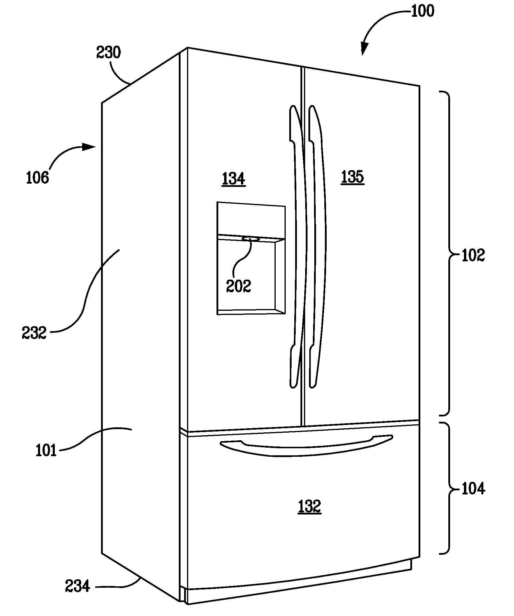
[0012] FIG. 1 is a perspective view of a refrigerator in accordance with an exemplary embodiment of the invention;
[0013] FIG. 2 is a perspective view of the refrigerator of FIG. 1 with the doors for the main fresh food compartment being open and with the drawer/door for the freezer compartment being removed;
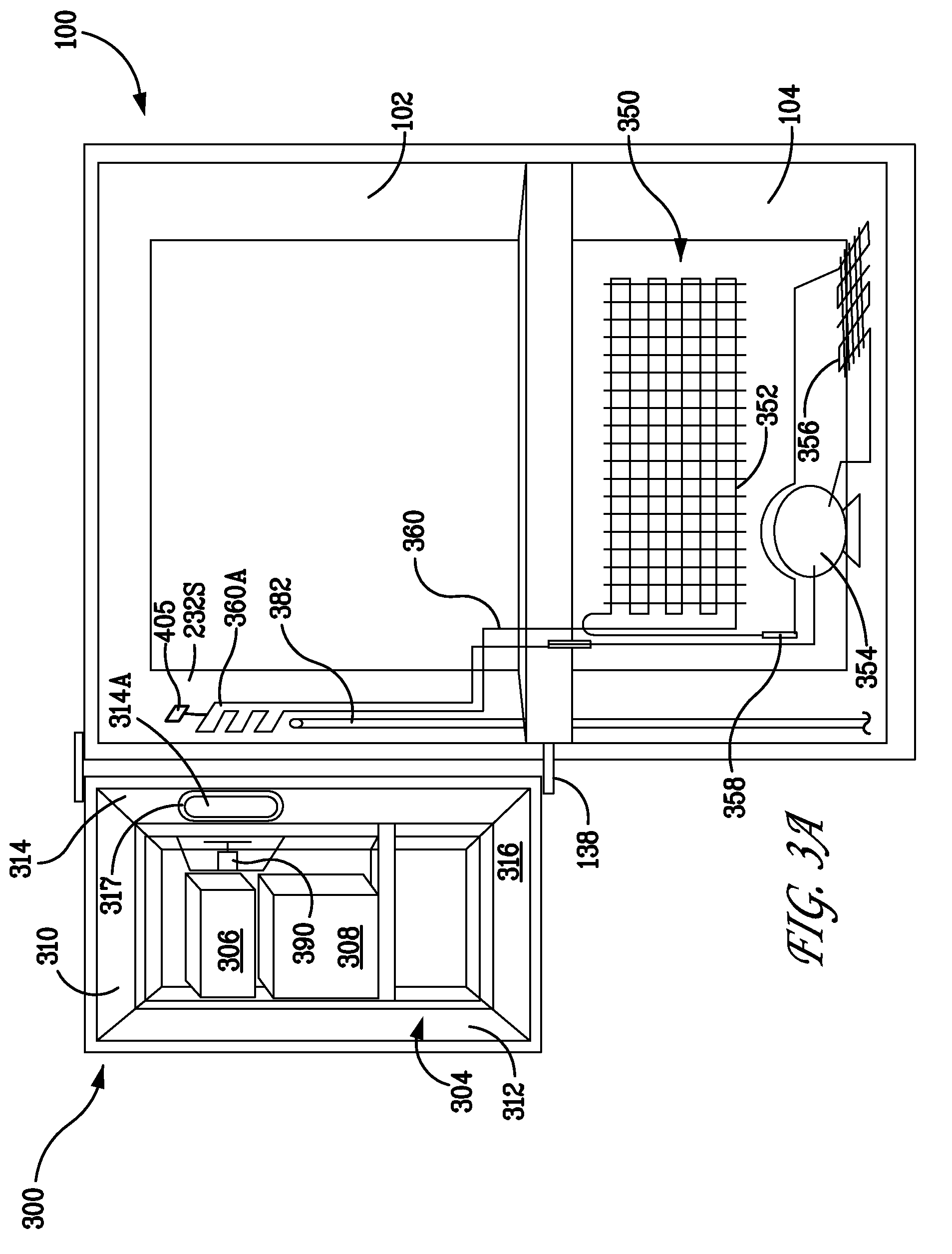
[0014] FIG. 3A partially and schematically shows some of the components of the refrigerator of FIG. 1, with one of the fresh food compartment doors open and the other being removed and the door for the sub-compartment and the drawer/door for the freezer compartment being removed;
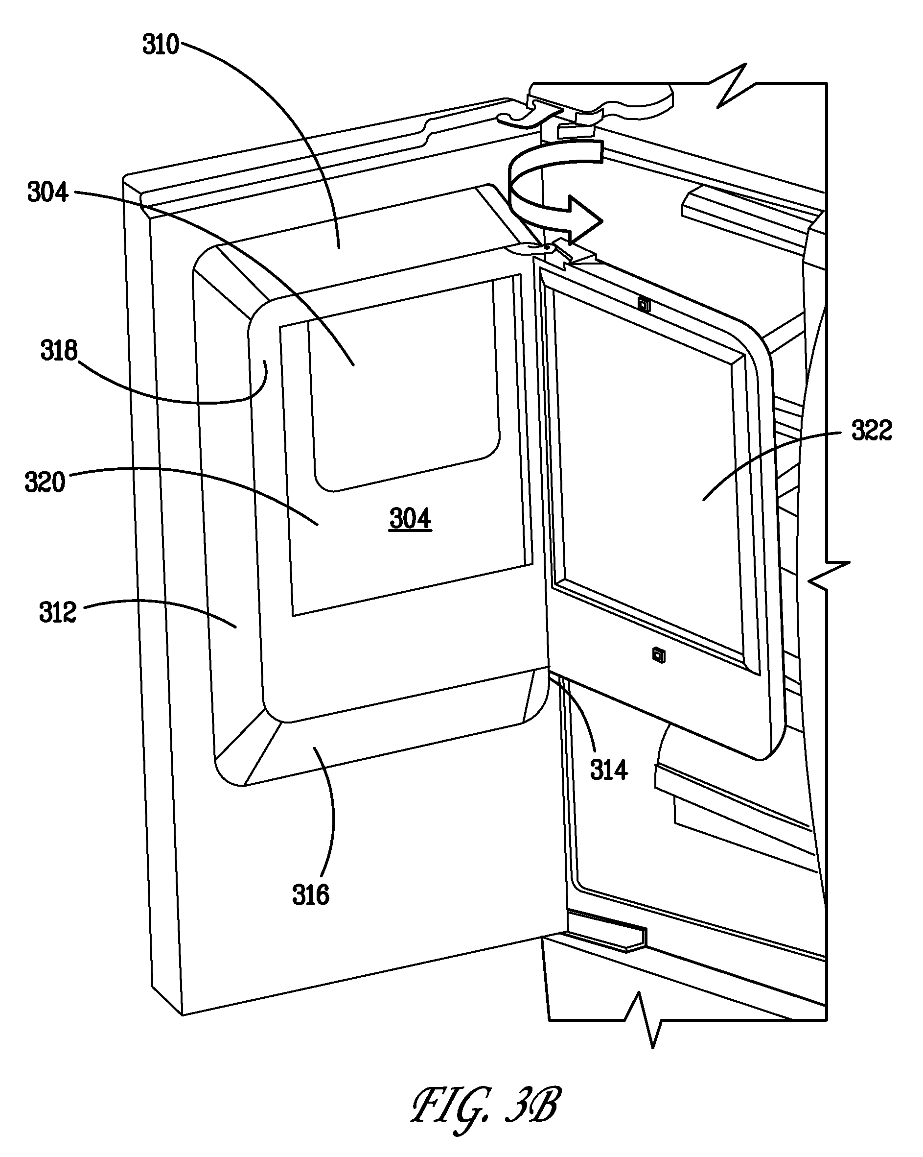
[0015] FIG. 3B is a perspective, partial view of a fresh food compartment door of the refrigerator of FIG. 2;
[0016] FIG. 4 is a partial schematic view of the heat exchanger and the ice sub-compartment of the refrigerator of FIG. 2 with the fresh food compartment door being closed;
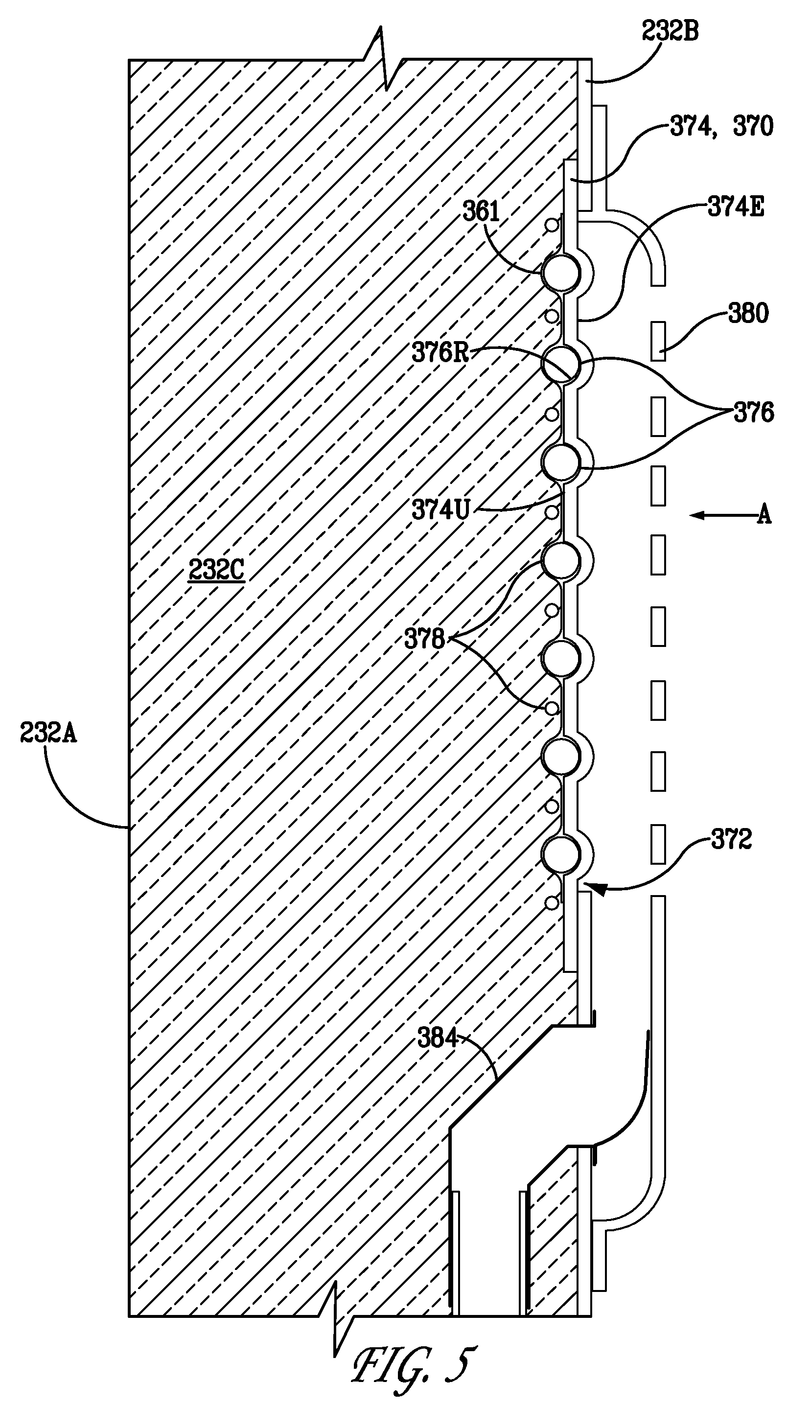
[0017] FIG. 5 is an enlarged, schematic view of the heat exchanger of FIG. 4;
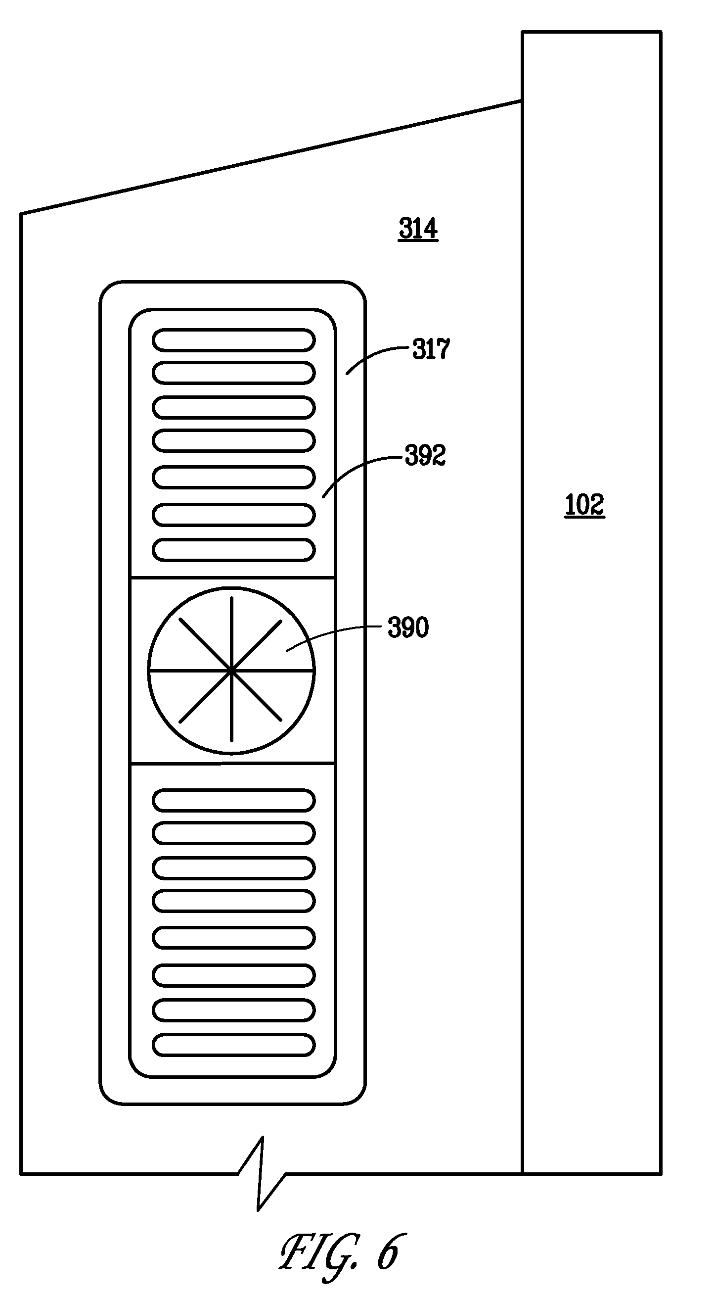
[0018] FIG. 6 is an enlarged, schematic side view of a portion of the fresh food compartment door, viewed along line 9-9 in FIG. 4;
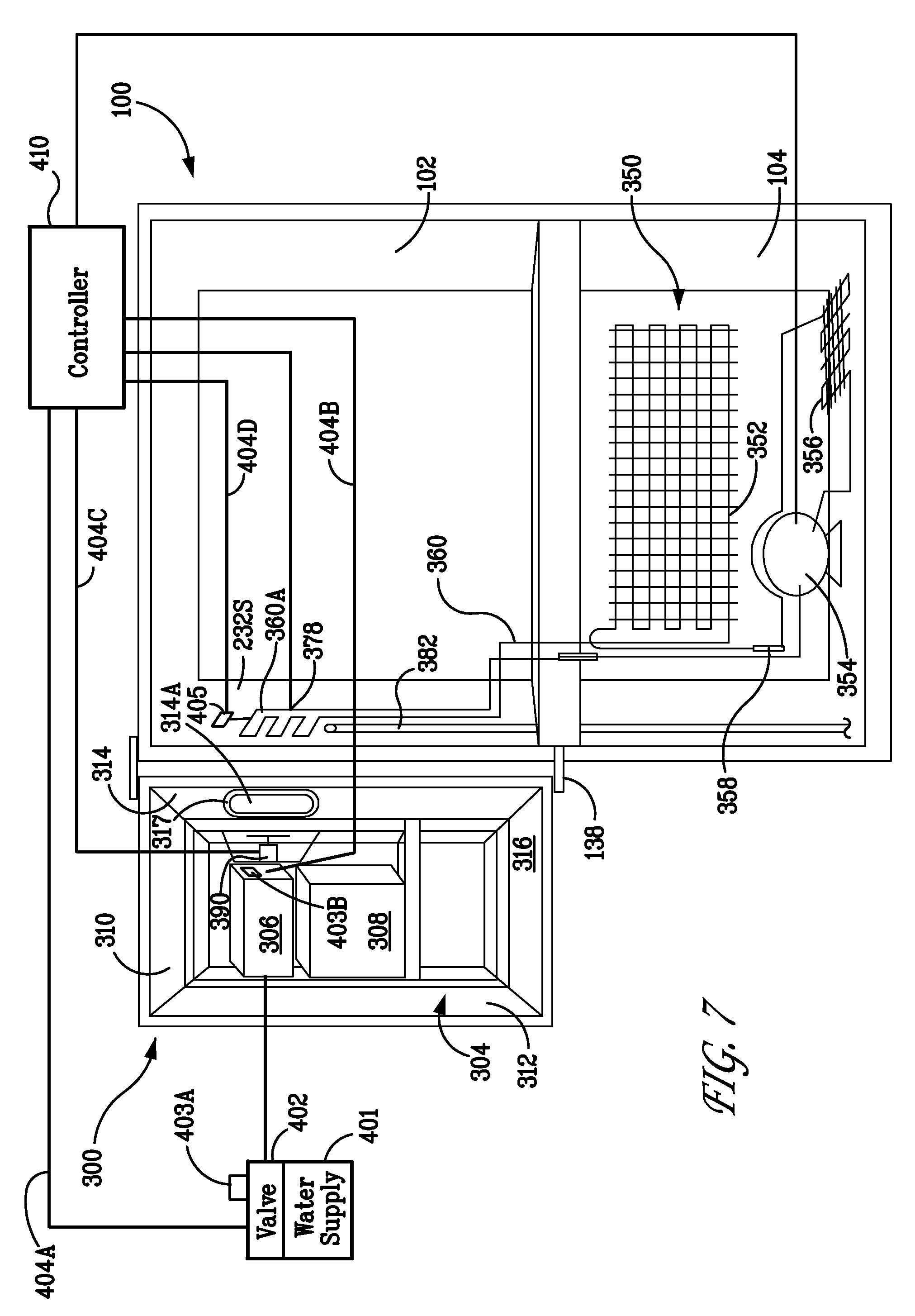
[0019] FIG. 7 partially and schematically shows some of the components of the refrigerator of FIG. 1 including a controller; and
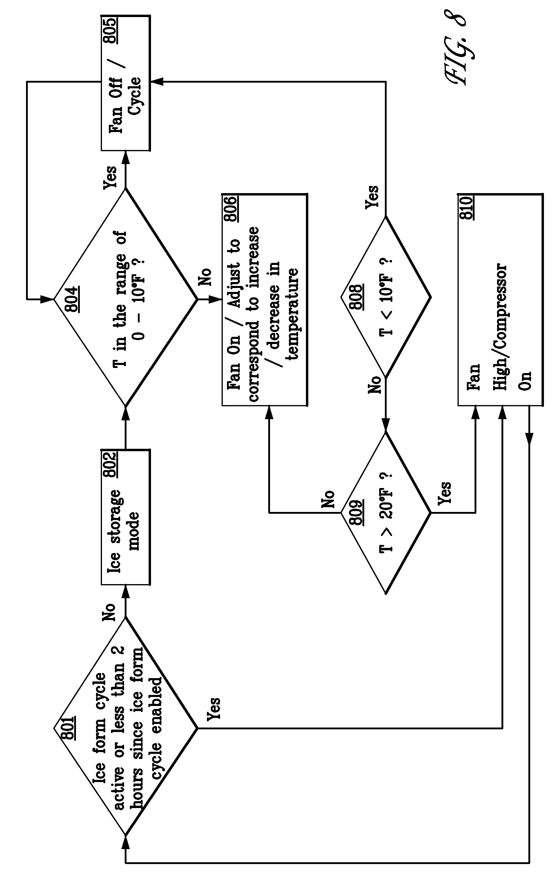
[0020] FIG. 8 is a flow diagram of an embodiment of a method incorporating aspects of the present disclosure.
DETAILED DESCRIPTION OF THE EXEMPLARY EMBODIMENTS OF THE INVENTION
[0021] Referring to FIGS. 1 and 2, a refrigerator in accordance with an exemplary embodiment of the invention is generally designated by reference numeral 100. The aspects of the disclosed embodiments are directed to controlling the temperature of the ice making compartment 300 of a door bottom mount refrigerator independently of the fresh food and freezer compartments 102, 104.
[0022] The refrigerator 100 has a main body 101 which defines therein a first, upper fresh food compartment 102 with a frontal access opening 102A, and a second, lower, freezer compartment 104 with a frontal access opening 104A. The fresh food compartment 102 and the freezer compartment 104 are arranged in a bottom mount configuration where the fresh food compartment 102 is disposed or positioned above the freezer compartment 104. The main fresh food compartment 102 is shown with two French doors 134 and 135. However, a single door or other suitable door arrangement can be used instead of the doors 134, 135. The freezer compartment 104 can be closed by a drawer or a door 132, as shown in FIG. 1.
[0023] As shown in FIG. 2, the main body 101 of the refrigerator 100 includes a top wall 230 and two sidewalls 232. The top wall 230 connects the sidewalls 232 to each other at the top ends thereof. A mullion 233, best shown in FIG. 2, connects the two sidewalls 232 to each other and separates the main compartment 102 from the freezer compartment 104. The main body 101 also includes a bottom wall 234, which connects the two sidewalls 232 to each other at the bottom ends thereof, and a back wall 235. As is known in the art, at least each of the sidewalls 232 includes an outer case 232A, a liner 232B, and a thermal insulation layer 232C disposed between the outer case 232A and the liner 232B (see FIG. 5). The thermal insulation layer 232C is made of a thermal insulation material such as a rigid polyurethane or other thermoset foam.
[0024] The drawer/door 132 and the doors 134, 135 close the frontal access openings 104A, 102A, respectively.
[0025] Each of the doors 134, 135 is mounted to the main body 101 by a top hinge 136 and a bottom hinge 138, thereby being rotatable approximately around the outer vertical edge of the fresh food compartment 102 between an open position for accessing the respective part of the fresh food compartment 102, as shown in FIG. 2, and a closed position for closing the respective part of the fresh food compartment 102, as shown in FIG. 1.
[0026] Similarly, when an access door 132 is used for the freezer compartment 104, it is rotatably attached to the main body 101 in a similar fashion. When a drawer is used for the freezer compartment 104, it is slidably received in the interior or cavity defined by the freezer compartment 104 in a known fashion.
[0027] As shown in FIGS. 2-4, an ice-making section 300 for freezing water and selectively discharging ice is mounted on the door 134 for the fresh food compartment 102. The ice-making section 300 is disposed substantially in the fresh food compartment 102 when the door 134 is in the closed position. The ice-making section 300 delivers ice through a chute formed in the door 134. The chute extends downward and/or outward from the ice-making section 300, with its lower end 202 being accessible from the exterior surface side of the door 134 (see FIG. 1). The lower end 202 is preferably positioned at a height facilitating convenient access to the ice. Of course, the ice-making section 300 can be mounted on the door 135 instead.
[0028] As illustrated in FIGS. 2 and 3A, the ice-making section 300 includes an ice sub-compartment 304 mounted on or partially formed by the liner of the door 134. An icemaker 306 is disposed in the sub-compartment 304. The ice-making section 300 preferably includes an ice storage bin 308 disposed in the sub-compartment 304 and below or underneath the icemaker 306. Since the fresh food compartment 102 normally has a temperature higher than the freezing point of water, the sub-compartment 304 is preferably thermally insulated to prevent or substantially reduce undesired heat transfer between air in the sub-compartment 304 and air in the fresh food compartment 102. The sub-compartment 304 has a top wall 310, two sidewalls 312, 314, a bottom wall 316, a front wall 318, and a back wall that can be formed by the inner liner of the door 134. As shown in FIG. 3B, preferably, the front wall 318 has an opening 320, and an access door 322 is pivotably or rotatably mounted to the front wall 318 in a known fashion for selectively closing the opening 320. To facilitate cooling of the ice sub-compartment 304, the sidewall 314 of the ice sub-compartment 304, which faces the sidewall 232S of the fresh food compartment 102 when the door 134 is closed, has an opening 314A. A gasket 317 is attached to the sidewall 314 and surrounds the opening 314A. The function of the opening 314A and the gasket 317 will be discussed in detail below.
[0029] Referring to FIG. 7, as is known in the art, water is delivered to one or more ice molds (not shown) of the icemaker 306 and then frozen into ice cubes. The water supply 401 is controlled by a valve 402. After the water is frozen into ice cubes, the ice cubes may be discharged from the ice molds and stored in the ice storage bin 308 until needed by a user. The ice cubes may be dispensed or withdrawn by accessing the ice storage bin 308 through the access door 322. The ice cubes, however, are typically dispensed via a chute by an ice-dispensing device, such as an auger or other mechanical device (not shown), installed in the door 134.
[0030] Referring now to FIG. 3A, in one embodiment, the refrigeration system 350 of the refrigerator 100 is preferably a single evaporator system. The system 350 includes evaporator 352 disposed in the freezer compartment 104, a compressor 354 disposed downstream of the evaporator 352 and outside of the freezer compartment 104, a condenser 356 disposed downstream of the compressor 354, an expansion valve 358 disposed downstream of the condenser 356, and a fluid connection loop 360 fluidly connecting these elements 352-358 together. The refrigeration system 350 contains therein a working medium (i.e., the refrigerant). Unlike known refrigerators, however, the fluid connection loop 360, which connects the evaporator 352 to the compressor 354 for transmitting the refrigerant, includes a serpentine portion 360A (i.e., the cooling serpentine) disposed or embedded in the sidewall 232S of the fresh food compartment 102 at a location proximate to the opening 314A in door 134 when the door 134 is closed. By this arrangement, the serpentine portion 360A can be used to cool the ice sub-compartment 304 as hereinafter described.
[0031] As shown in FIG. 5, the liner 232B of the sidewall 232S of the fresh food compartment 102 has an opening 372 that preferably faces or is substantially aligned with the opening 314A of the sidewall 314 of the sub-compartment 304 when the door 134 is in the closed position. In one embodiment, a heat exchanger 370, which includes a formed metal heat-exchanging plate 374, is attached to the liner 232B and covers the opening 372. The heat exchanger 370 is thermally coupled to the serpentine portion 360A of the fluid connection loop 360 so that the refrigerant, when passing through the serpentine portion 360A, cools the heat-exchanging plate 374. When the door 134 is closed, the heat-exchanging plate 374 is substantially aligned with the opening 314A. The gasket 317 touches/presses the sidewall 232S and surrounds the heat-exchanging plate 374 so that the heat-exchanging plate 374 is exposed to the interior of the sub-compartment 304, while the gasket 317 substantially seals the heat-exchanging plate 374 and the interior of the ice maker compartment 304 from the rest of the fresh food compartment 102. In other words, when the door 134 is closed, part of the sidewall 232S including the heat-exchanging plate 374, the gasket 317 and the sub-compartment 304 form or define a substantially sealed interior space.
[0032] Referring still to FIGS. 3A-5, preferably, the serpentine portion 360A of the fluid connection loop 360 has a plurality of bent sections 361. The heat-exchanging plate 374 preferably has a plurality of projections 376 which extend outward from its first, exposed surface 374E. Preferably, each of the projections 376 has a curved cross-section (substantially semi-spherical cross sections are shown in FIG. 5, so that the projections 376 also define receiving channels 376R on the second, un-exposed, foam-facing surface 374U of the heat-exchanging plate 374 for receiving the respective bent sections 361. Such projections 376 enhance not only the heat exchange between the bent sections 361 and the heat-exchanging plate 374, but also the heat exchange between the heat-exchanging plate 374 and the air in the ice sub-compartment 304.
[0033] As shown in FIGS. 4 and 5, an appearance enhancing louvered cover 380 is preferably used to cover the heat-exchanging plate 374. The louvered cover 380, which is supported by the liner 232B, is spaced apart from the heat-exchanging plate 374.
[0034] Referring to FIG. 5, in one embodiment, a defrost heater 378 can be thermally coupled to the heat-exchanging plate 374 to remove frost that may form on the exposed surface of the heat-exchanging plate 374. In one embodiment, the defrost heater 378 is an aluminum foil defrost heater comprising foil layer 378A and resistive heater coils 378B. In alternate embodiments, the defrost heater 378 can comprise any suitable heater for warming the heat-exchanging plate 374. In this embodiment, the bent sections 361 of the serpentine portion 360A are sandwiched between the heat-exchanging plate 374 and a layer of aluminum foil that overlays the foam-facing surface 374U of plate 374. A drain tube 382 (shown in FIG. 4), preferably embedded in the sidewall, with an inlet proximate the lower end of the heat-exchanging plate 374, is provided for directing the defrost water to a drain pan (not shown) which may be the evaporator drain pan. As shown in FIG. 5, a scoop 384 is located proximate the lower ends of the heat-exchanging plate 374 and the louvered cover 380 for directing the defrost water from the heat-exchanging plate 374 and the louvered cover into the drain tube 382. The scoop 384 may have a configuration that covers the entire width of the heat-exchanging plate 374 and the entire width of the louvered cover 380. Preferably the scoop 384 is made of a flexible material such as rubber or soft plastic so as to not interfere with the door foaming process.
[0035] Referring now to FIGS. 5-7, an electric fan 390 is located in the ice sub-compartment 304 for facilitating the heat exchange between the air in the ice sub-compartment 304 and the heat-exchanging plate 374 when the door 132 is closed. Preferably, the fan is disposed adjacent to the opening 314A. As shown in FIGS. 6 and 7, a louvered fan bracket 392 is preferably used to at least partially cover the opening 314A and to support the fan 390. The fan 390 directs air in the direction A towards the exposed surface of heat-exchanging plate 374. As the air then moves over the exposed surface of the plate 374, cooled by the coolant passing through the cooling serpentine 360A, heat is absorbed by the plate 374 and the chilled air recirculates through the ice sub-compartment 304. By this arrangement, the air in the ice sub-compartment 304 is chilled sufficiently to form ice in the icemaker during an ice forming cycle and maintain a freezing temperature during an ice storage cycle.
[0036] The icemaker 306, the defrost heater 378 and the fan 390 may be powered by a common power source or by a dedicated power source of their own.
[0037] The aspects of the disclosed embodiments are directed to controlling the temperature of the heat-exchanging plate 374 of a door bottom mount refrigerator 100 for ice formation, ice storage and defrost cycles. A single thermistor located on the heat-exchanging plate 374 is used to determine a cooling fan speed for the ice sub-compartment 304 as well as determine the time to terminate a defrost cycle of the heat-exchanging plate 374.
[0038] In one embodiment, the temperature of the heat-exchanging plate 374 is used as an indirect indicator of the temperature of the ice making section 300, and in particular the ice sub-compartment 304. As described above, the circulation of the refrigerant through the serpentine portion 360A causes the heat-exchanging plate 374 to cool and the fan 390 forces air across the heat-exchanging plate 374. The cooled air is directed into the ice sub-compartment 304, which causes the ice sub-compartment 304 to cool. As such, the sensed temperature of the heat-exchanging plate 374 can be used as an indirect measure of the temperature of ice sub-compartment 304. An inference is made that the temperature of the ice sub-compartment 304 corresponds relatively to the temperature of the heat-exchanging plate 374.
[0039] In one embodiment, as shown in FIGS. 3A and 7, a thermistor 405 is thermally coupled to the heat-exchanging plate 374. The thermistor 405 is used to monitor or detect the temperature of the heat-exchanging plate 374 and generally comprises a heat sensing device, such as for example, a thermocouple. In alternate embodiments, the thermistor 405 can comprise any suitable heat detecting device or sensor that is configured to detect a relative temperature of an object. The temperature of the heat-exchanging plate 374 will herein be referred to as temperature T.
[0040] Generally, in a refrigerator 100 where the ice-making section 300 is mounted on the door 134 for the fresh food compartment 102, the ice-making section 300 can only make ice when the compressor 354 is running When the compressor 354 is not running, the ice sub-compartment 304 will typically be too warm to make or store ice. The cooling or refrigeration system 350 will generally follow cooling cycles that are based on the temperatures of the fresh food 102 and the freezer compartments 104, meaning that the compressor 354 will run only in response to the temperature of the compartments 102, 104. However, because the ice sub-compartment 304 is separate from the fresh food and freezer compartments 102, 104, the temperature of the ice sub-compartment needs to be separately monitored and controlled in order to maintain the desired temperatures during ice formation and ice storage cycles.
[0041] The aspects of the disclosed embodiments allow for the monitoring and control of the temperature of the ice sub-compartment 304 independently of compartments 102, 104. In addition, temperature T as monitored by thermistor 405, is used to control the speed of fan 390 and the independent control of the compressor 354, even when the fresh food compartment 102 and the freezer compartment 104 do not require cooling. This independent monitoring and control of the temperature of ice sub-compartment 304 enables the ice sub-compartment 304 to maintain suitably cold temperatures during ice forming and ice storage cycles.
[0042] During an ice formation cycle, it is desirable to maintain temperatures in the ice sub-compartment 304 well below freezing, such as in the range of approximately 0 to 10 degrees Fahrenheit. In alternate embodiments, the temperature of the ice sub-compartment 304 during an ice formation cycle can be any suitable freezing temperature. When the compressor 354 is running, the temperature of the heat exchanging plate 374 will generally be colder than the ice sub-compartment 304. Increasing the speed of the fan 390 in this state or cycle will increase the heat transfer across the heat exchanging plate 374 and correspondingly reduce the temperature of the ice sub-compartment 304. Thus, in order to optimize the heat transfer and cooling during the ice formation cycle, the speed of the fan 390 is set to a high speed while the compressor 354 is running.
[0043] Thermistor 405 can be used during the ice formation cycle to monitor the temperature of the heat-exchanging plate 374 to ensure that the temperature remains in a suitable freezing range for ice formation. Temperature T of the heat-exchanging plate 374 during ice formation can also be used to run compressor 354 even when compartments 102, 104 do not require cooling, and to increase or decrease fan speed to ensure that an appropriate temperature is maintained for ice formation in the ice sub-compartment 304.
[0044] When the ice-making section 300 is not in the ice formation cycle, the ice-making section 300 will typically be in an ice storage cycle. In this state, the temperature of the ice sub-compartment 304 can be maintained at a temperature that is warmer than the freezing temperature range for ice formation. In one embodiment, a desired temperature of the ice sub-compartment 304 during the ice storage cycle is approximately 20 degrees Fahrenheit. In the ice storage cycle, when the heat exchanging plate 374 is cold, or in the range of 0 to 10 degrees Fahrenheit, or such other suitable freezing temperature, the inference is made that the temperature of the ice sub-compartment 304 is in the range of a suitable freezing temperature and does not require additional cooling. The fan 390 can be set to run at a slow speed and/or cycle off. When the temperature of the heat exchanging plate 374 is warmer than 0 to 10 degrees Fahrenheit, the fan 390 can be set to run at a higher speed in order to provide additional cooling to the ice sub-compartment 304. When the temperature T exceeds a pre-determined temperature setpoint, such as for example, 20 degrees Fahrenheit, the speed of the fan 390 can be set to high, and the compressor 354 activated.
[0045] In one embodiment, both during ice formation and ice storage, when the fan 390 is activated or turned on, the compressor 354 will also be on, or activated. The activation of the compressor 354 can occur whenever the fan 390 comes on or only when the speed of the fan 390 is set to high. In one embodiment, the speed of the fan 390 can be adjusted across a range, where the speed of the fan 390 increases as the temperature T of the heat-exchanging plate 374 increases. Once the compressor 354 is activated, the temperature of the heat-exchanging plate 374 will decrease. The speed of the fan 390 can be accordingly adjusted to lower speeds as the temperature of the heat-exchanging plate 374 decreases, depending upon the cooling and temperature requirement for the ice sub-compartment 304 at the time.
[0046] In one embodiment, the temperature reading of the thermistor 405 from the heat-exchanging plate 374 is also used to control and terminate a defrost cycle of the refrigerator 100. When the defrost cycle is initiated, the defrost heater 378 is energized to warm the heat-exchanging plate 374 in order to melt any frost build-up or accumulation from the heat-exchanging plate 374. The defrost heater 378 can be de-energized when the temperature reading of the thermistor 405 indicates that the temperature of the heat-exchanging plate is above the freezing point or other pre-determined temperature set point, such as for example 40 degrees Fahrenheit. Alternatively, the defrost heater can be de-energized at any suitable point where it can be determined that all of the frost has melted.
[0047] In one embodiment, the defrost heater 378 remains energized until the temperature of the heat-exchanging plate 374, as detected by the thermistor 405 is at a suitable temperature setpoint above the freezing point, or a pre-determined time period has elapsed. It may be desirable to control the length of time that the defrost heater 378 remains energized, in the event that the thermistor 405 malfunctions or becomes disconnected. Thus, in one embodiment, in addition to controlling the defrost cycle based on the temperature of the heat-exchanging plate 374, a maximum time period for the defrost heater 378 to remain energized will also be set.
[0048] Since the temperature of the heat-exchanging plate 374 is measured remotely from the ice sub-compartment 304, the temperature of the ice sub-compartment 304 cannot be obtained directly from the reading of thermistor 405. Generally, the temperature of the heat-exchanging plate 374 will be colder than the temperature of the ice sub-compartment 304 when the compressor 354 and fan 309 are running In one embodiment, the temperature difference can be approximately 10 degrees Fahrenheit. In one embodiment, an estimate of the temperature of the ice sub-compartment 304 is based on the reading of the thermistor 405. The estimate can take into account any one or more factors or parameters that may affect the correlation of temperature readings from the temperature of the heat-exchanging plate 374 to the ice sub-compartment 304. In one embodiment, these parameters can include, for example, the average of the readings from thermistor 405, a delay or offset factor, the freezer temperature and the ambient air temperature. In alternate embodiments, any suitable environmental or other factor that may affect the temperature reading of the thermistor 405 can be considered in estimating the temperature of the ice sub-compartment 304.
[0049] In one embodiment, the temperature readings of the thermistor 405 are averaged over a specific time period or time duration. The averaging may be performed while the fan 390 is running to lessen the direct effect of the heat-exchanging plate 374 on the thermistor 405.
[0050] The temperature of the freezer compartment 104 will also have an effect on the temperature reading of the thermistor 405. In one embodiment, the average temperature of the heat exchanging plate 374 can be a function of the temperature of the freezer compartment 104, since when the compressor 354 is running, the refrigerant is circulating through the serpentine portion 360A, and having a cooling effect on the heat-exchanging plate 374. In one embodiment, the temperature of the freezer compartment 104 is factored into the estimate of the temperature of the ice sub-compartment 304 from the temperature reading by the thermistor 405.
[0051] Additionally, in one embodiment, the ambient temperature outside the refrigerator 100 can be factored into the algorithm for estimating the temperature of the ice sub-compartment 304 from the reading of the thermistor 405. Generally, the ambient temperature will affect the heat leakage into the fresh food and freezer compartments 102, 104. This leakage can affect the temperature reading by the thermistor 405. Each of these factors can be taken into account when estimating the temperature of the ice sub-compartment 304 from the temperature reading by the thermistor 405. In one embodiment, a look-up table can be constructed based on known or predetermined relationships between the temperature reading of the thermistor 405 from the heat-exchanging plate 374 and the temperature of the ice sub-compartment 304.
[0052] FIG. 7 illustrates an example of one embodiment of a refrigerator 100 that includes a controller 410 that can be used for controlling the refrigerator 100 in accordance with the aspects of the disclosed embodiments. In this embodiment, controller 410 is configured to control the various functions of the refrigerator 100 and the ice making section 300 in response to the sensed temperature T of the heat exchanging plate 374, and other operational events and environmental effects. Although the controller 410 is shown in this example as a separate subsystem of the refrigerator 100, in one embodiment, the controller 410 is embodied as an integral component of the refrigerator 100.
[0053] In one embodiment, the icemaker 306 obtains water for preparing ice cubes from water supply 401 though an appropriate valve 402. The icemaker 306 can include a sensor 403A that is configured to detect the actuation of the valve 402 for filling the ice molds (not shown) of the icemaker 306. In one embodiment, the sensor 403A comprises a water flow sensor that detects the flow of water through the valve or the opening of the valve. Signal 404A that is generated by sensor 403A can be used by the controller 410 to determine that the icemaker 306 is in an ice formation cycle. As previously noted, the dispensing of ice from the icemaker 306 can also be used as an indication to activate the ice formation cycle. In one embodiment, the icemaker 306 includes a sensor 403B that is configured to detect the movement of the auger (not shown) for dispensing ice. The sensor 403B can comprise a Hall effect sensor, or such other suitable sensor that is configured to detect movement of the auger, or an activation switch that detects the activation of the ice dispenser. Signal 404B generated by sensor 403B can be used by the controller 404 as an indication to initiate an ice formation cycle as is described herein.
[0054] In one embodiment, the controller 410 is electrically coupled to the fan 390 and refrigeration system 350. The controller 410 is configured to provide a speed control signal 404C to the fan 390. The speed control signal 390 is used to adjust and set the speed of the fan 390 in accordance with the embodiments disclosed herein. For example, when the controller 410 detects the initiation of the ice formation mode, the controller 410 can activate the refrigeration system 350 and set the speed of the fan 390 to high. Generally, the initiation of the ice formation cycle will override the control of the refrigeration system 350 by the fresh food and freezer compartments 102, 104. The controller 410 can enable the refrigeration system 350, and in particular compressor 354, to run even though the temperatures of the fresh food and freezer compartments 102, 104 do not call for additional cooling. In one embodiment, the controller 410 is configured to control the components of the refrigeration system 350 to avoid overcooling of the fresh food or freezer compartments 102, 104, when the heat exchanger 370 is being cooled.
[0055] The thermistor 405 is mounted at the heat-exchanging plate 374, and suitably positioned to detect the temperature T of the heat-exchanging plate 374. In one embodiment, the thermistor 405 is configured to generate a signal 404D that can be used by the controller 410 to determine a temperature of the heat exchanging plate 374.
[0056] FIG. 8 illustrates one example of a process flow incorporating aspects of the disclosed embodiments. In one embodiment, it is determined 801 whether an ice formation cycle is active or an elapsed time period since a last activation of the ice formation cycle is greater than a pre-determined time period. The pre-determined time period can be any suitable time period, such as for example, two hours. Generally, the pre-determined time period is a period during which ice will form or harden during an ice formation cycle.
[0057] If the ice formation cycle is active or less than two hours has elapsed since the activation of the ice formation cycle, the state 810 of the fan 390 set to high and the compressor 354 is set to on.
[0058] If the ice formation cycle is not active and the elapsed time period exceeds the pre-determined time period, an ice storage cycle or mode 802 of the ice-making section 300 is enabled. In one embodiment, in the ice storage cycle, a speed of the fan 390 is initially set to a low speed or off. The speed of the fan 390 can also be cycled on and off according to a pre-determined duty cycle, such as for example, approximately 50%. In one embodiment, in the ice storage mode, the cycles of the compressor 354 will generally correspond to the typical cooling cycles that are based on the temperature requirements of the fresh food 102 and the freezer compartments 104. In this state, when the compressor 354 cycles on due to a call from the fresh food or freezer compartments 102, 104, the heat-exchanging plate 374 will also be cooled. If the fan 390 runs during this period, cooling will be provided to the ice sub-compartment 304 as described above.
[0059] In the ice storage mode 802, once the fan 390 is set to low or off, the temperature T of the heat-exchanging plate 374 is monitored by thermistor 405. In one embodiment, it is determined 804 if the temperature of the heat exchanging plate 374 is in the range of approximately 0-10 degrees Fahrenheit. If yes, the speed of the fan 390 remains at the low, off or cycling setting 805. If the temperature of the heat exchanging plate 374 exceeds the range of 0-10 degrees Fahrenheit, the speed of the fan 390 can be increased at 806. In one embodiment, the speed of the fan 390 can be increased incrementally over a range from low to high and can be adjusted relative to the detected temperature. For example, in one embodiment, if the temperature is in the range of 0-10 degrees, the speed of the fan 390 can be set to off, or cycled on/off as described above. If the temperature is in a range of approximately 10-15 degrees Fahrenheit, the speed of the fan 390 can be increased to a mid-level speed. A high speed setting of the fan 390 can be activated when the temperature T is at or above approximately 20 degrees Fahrenheit.
[0060] Correspondingly, if the temperature T decreases, the speed of the fan 390 can be reduced. For example, if the temperature T falls below 10 degrees Fahrenheit, the setting of the fan 390 can be adjusted to be off or in the cycling state 805. If it is determined 809 that the temperature T remains less than approximately 20 degree Fahrenheit, or in the range of 10 to 20 degrees Fahrenheit, the speed of the fan 390 can continue to be adjusted 806 accordingly. If the temperature exceeds approximately 20 degrees Fahrenheit, the fan 390 and compressor 354 can be set to the high/on state 810.
[0061] In one embodiment, the fan 390 will only be on when the compressor 354 is on. When the compressor 354 is on, the heat-exchanging plate 374 will be cooled by the circulating working medium. Generally, when the compressor 354 is on, the temperature T of the heat-exchanging plate 374 will be cooler than the ice sub-compartment 304.
[0062] The disclosed embodiments may also include software and computer programs incorporating the process steps and instructions described above. In one embodiment, the programs incorporating the process described herein can be stored on or in a computer program product and executed in one or more computers. The controller 410 illustrated in FIG. 7 can include computer readable program code means stored on a computer readable storage medium, such as a memory for example, for carrying out and executing the process steps described herein. In one embodiment, the computer readable program code is stored in a memory of the apparatus 700. In alternate embodiments, the computer readable program code can be stored in memory or memory medium that is external to, or remote from, the controller 410. The memory can be direct coupled or wireless coupled to the controller 410.
[0063] The controller 410 may be linked to another computer system or controller (not shown), such that the controllers are capable of sending information to each other and receiving information from each other. In one embodiment, the controller 410 could include a server computer or controller adapted to communicate with a network, such as for example, a wireless network or the Internet.
[0064] The controller 410 is generally adapted to utilize program storage devices embodying machine-readable program source code, which is adapted to cause the controller 410 to perform the method steps and processes disclosed herein. The program storage devices incorporating aspects of the disclosed embodiments may be devised, made and used as a component of a machine utilizing optics, magnetic properties and/or electronics to perform the procedures and methods disclosed herein. In alternate embodiments, the program storage devices may include magnetic media, such as a diskette, disk, memory stick or computer hard drive, which is readable and executable by a computer. In other alternate embodiments, the program storage devices could include optical disks, read-only-memory ("ROM") floppy disks and semiconductor materials and chips.
[0065] The controller 410 may also include a microprocessor for executing stored programs, and may include a data storage or memory device on its program storage device for the storage of information and data. The computer program or software incorporating the processes and method steps incorporating aspects of the disclosed embodiments may be stored in one or more computer systems or on an otherwise conventional program storage device.
[0066] The aspects of the disclosed embodiments are directed to controlling the temperature of the heat-exchanging plate 374 of a door bottom mount refrigerator 100 for ice formation, ice storage and defrost cycles. A single thermistor located on the heat-exchanging plate 374 is used to determine a cooling fan speed for the ice sub-compartment 304 as well as determine the time to terminate a defrost cycle of the heat-exchanging plate 374. The monitoring and control of the temperature of the ice sub-compartment 304 is carried out independently of the fresh food and freezer compartments 102, 104.
[0067] Moreover, it is expressly intended that all combinations of those elements and/or method steps which perform substantially the same function in substantially the same way to achieve the same results are within the scope of the invention. Moreover, it should be recognized that structures and/or elements and/or method steps shown and/or described in connection with any disclosed form or embodiment of the invention may be incorporated in any other disclosed or described or suggested form or embodiment as a general matter of design choice. It is the intention, therefore, to be limited only as indicated by the scope of the claims appended hereto.
* * * * *
D00000
D00001
D00002
D00003
D00004
D00005
D00006
D00007
D00008
D00009
XML
uspto.report is an independent third-party trademark research tool that is not affiliated, endorsed, or sponsored by the United States Patent and Trademark Office (USPTO) or any other governmental organization. The information provided by uspto.report is based on publicly available data at the time of writing and is intended for informational purposes only.
While we strive to provide accurate and up-to-date information, we do not guarantee the accuracy, completeness, reliability, or suitability of the information displayed on this site. The use of this site is at your own risk. Any reliance you place on such information is therefore strictly at your own risk.
All official trademark data, including owner information, should be verified by visiting the official USPTO website at www.uspto.gov. This site is not intended to replace professional legal advice and should not be used as a substitute for consulting with a legal professional who is knowledgeable about trademark law.