Steam Turbine Power Plant And Operation Method Thereof
OKITA; Nobuo ; et al.
U.S. patent application number 12/787176 was filed with the patent office on 2010-12-30 for steam turbine power plant and operation method thereof. This patent application is currently assigned to KABUSHIKI KAISHA TOSHIBA. Invention is credited to Nobuhiko Hattori, Yasunori Matsuura, Nobuo OKITA.
| Application Number | 20100326074 12/787176 |
| Document ID | / |
| Family ID | 42341210 |
| Filed Date | 2010-12-30 |


| United States Patent Application | 20100326074 |
| Kind Code | A1 |
| OKITA; Nobuo ; et al. | December 30, 2010 |
STEAM TURBINE POWER PLANT AND OPERATION METHOD THEREOF
Abstract
According to one aspect of the embodiment, a steam turbine power plant 10 is provided with a steam turbine system 20 which generates electricity by driving a steam turbine by the steam from a boiler 21 or the like which generates the steam by combustion heat, and a carbon dioxide recovery system 50 which recovers carbon dioxide contained in the combustion gas from the boiler 21 or the like. In the steam turbine system 20, part of the steam having performed the expansion work in a high-pressure turbine 22 is introduced into a back-pressure turbine 27. The steam introduced into the back-pressure turbine 27 performs the expansion work and partly supplied to the carbon dioxide recovery system 50 through a pipe 42 to heat an absorption liquid 90 in a regeneration tower 70.
| Inventors: | OKITA; Nobuo; (Yokohama-shi, JP) ; Matsuura; Yasunori; (Tokyo, JP) ; Hattori; Nobuhiko; (Tokyo, JP) |
| Correspondence Address: |
    FOLEY AND LARDNER LLP;SUITE 500
    3000 K STREET NW
    WASHINGTON
    DC
    20007
    US
|
| Assignee: | KABUSHIKI KAISHA TOSHIBA |
| Family ID: | 42341210 |
| Appl. No.: | 12/787176 |
| Filed: | May 25, 2010 |
| Current U.S. Class: | 60/648 ; 60/649; 60/653 |
| Current CPC Class: | Y02E 20/326 20130101; F01K 7/04 20130101; B01D 53/1475 20130101; B01D 2257/504 20130101; Y02C 10/06 20130101; Y02C 20/40 20200801; Y02E 20/32 20130101; F01K 7/025 20130101; Y02C 10/04 20130101; B01D 53/62 20130101; F22B 37/008 20130101; B01D 53/1425 20130101; F01K 17/06 20130101; B01D 2251/80 20130101 |
| Class at Publication: | 60/648 ; 60/653; 60/649 |
| International Class: | F01K 7/38 20060101 F01K007/38; F01K 7/16 20060101 F01K007/16; F01K 17/00 20060101 F01K017/00 |
Foreign Application Data
| Date | Code | Application Number |
|---|---|---|
| May 28, 2009 | JP | P2009-129068 |
Claims
1. A steam turbine power plant, comprising: a steam turbine system, the steam turbine system comprises: a boiler comprising a superheater; a first steam turbine into which main steam is introduced from the superheater of the boiler; a reheater which reheats the steam discharged fluid the first steam turbine; a second steam turbine into which the steam reheated by the reheater is introduced; a third steam turbine into which the steam discharged from the second steam turbine is introduced; a first electric generator which is driven by the third steam turbine; a condenser which condensates the steam discharged from the third steam turbine into a condensate; a feed water heater which heats the condensate to introduce into the boiler as feed water and a fourth steam turbine into which part of the steam discharged from the first steam turbine is introduced, and a carbon dioxide recovery system, the carbon dioxide recovery system comprises: an absorption tower which absorbs the carbon dioxide contained in combustion gas from the boiler by an absorption liquid; a regeneration tower which separates the carbon dioxide from the absorption liquid by heating the absorption liquid having absorbed the carbon dioxide by the steam discharged from the fourth steam turbine; and a recovery apparatus which recovers the carbon dioxide separated by the regeneration tower.
2. The steam turbine power plant according to claim 1, wherein the second steam turbine is composed of two steam turbines, one of the two steam turbines is introduced with the steam obtained by reheating by the reheater the steam discharged from the first steam turbine, the other of the two steam turbines is introduced with the steam obtained by reheating by the reheater the steam discharged from the one of the two steam turbines, and the steam discharged from the other of the two steam turbines is introduced into the third steam turbine.
3. The steam turbine power plant according to claim 1, further comprising, a second electric generator which is driven by the fourth steam turbine.
4. The steam turbine power plant according to claim 1, wherein the steam extracted from the fourth steam turbine is guided to the feed water heater.
5. The steam turbine power plant according to claim 1, further comprising, a pressure regulating valve which adjusts the pressure of the steam discharged from the fourth steam turbine.
6. The steam turbine power plant according to claim 1, further comprising, a flow rate regulating valve which introduces part of the steam discharged from the second steam turbine into a predetermined stage of the fourth steam turbine while adjusting the flow rate.
7. The steam turbine power plant according to claim 2, further comprising, a flow rate regulating valve which introduces part of the steam discharged from the one of the two steam turbines into a predetermined stage of the fourth steam turbine while adjusting the flow rate.
8. The steam turbine power plant according to claim 1, further comprising, a flow rate regulating valve which adjusts the flow rate of the steam, which is discharged from the fourth steam turbine and used to heat the absorption liquid in the regeneration tower based on the temperature of the absorption liquid in the regeneration tower.
9. The steam turbine power plant according to claim 1, further comprising, a flow rate regulating valve which adjusts the flow rate of the steam, which is discharged from the fourth steam turbine and used to heat the absorption liquid in the regeneration tower based on the flow rate of the absorption liquid in the regeneration tower.
10. An operation method of a steam turbine power plant comprising: a boiler having a superheater and a reheater; a first steam turbine which is driven by steam introduced form the superheater of the boiler and discharges the steam to the reheater; a second steam turbine which is driven by the steam from the reheater; a third steam turbine which is driven by the steam discharged from the second steam turbine; a fourth steam turbine which is driven by part of the steam discharged from the first steam turbine; a condenser which condensates the steam discharged from the third steam turbine into a condensate; a feed water heater which is disposed on a feed water system between the condenser and the boiler and heats the feed water guided from the condenser; an absorption tower which has combustion gas guided into it from the boiler and an absorption liquid supplied into it and which absorbs the carbon dioxide contained in the combustion gas by the absorption liquid; and a regeneration tower which diffuses the absorbed carbon dioxide by heating the absorption liquid having absorbed the carbon dioxide in the absorption tower, wherein the steam extracted from the fourth steam turbine is used as a heat source for the feed water by the feed water heater, and the steam discharged from the fourth steam turbine is used as a heat source for heating the absorption liquid in the regeneration tower.
Description
CROSS REFERENCE TO RELATED APPLICATIONS
[0001] This application is based upon and claims the benefit of priority from the prior Japanese Patent Application No. 2009-129068 filed on May 28, 2009; the entire contents of which are incorporated herein by reference.
FIELD
[0002] Embodiments described herein relates generally to a steam turbine power plant comprising a steam turbine, a boiler, a turbine generator and the like and an operation method thereof, more particularly to a steam turbine power plant provided with an apparatus which increases a steam temperature to improve power generation efficiency and separates CO.sub.2 contained in the combustion gas exhausted from the boiler to recover it, and an operation method thereof.
BACKGROUND
[0003] Since a conventional steam turbine power plant has steam temperature conditions including 600.degree. C. or below, the configuration members, such as a turbine rotor, a rotor blade, a nozzle and the like which are exposed to high temperatures, are made of a ferritic heat-resistant steel having outstanding productivity and economical efficiency. On the other hand, carbon steel has been used for materials configuring, for example, a feed water heater which is not exposed to high temperatures.
[0004] Meanwhile, the provision of high efficiency to the steam turbine power plant is being performed vigorously in view of fuel saving and environmental protection in these years. For example, a steam turbine using high-temperature steam at a temperature of about 600.degree. C. (620.degree. C. or below) is being operated. The steam turbine using such high-temperature steam has quite a few parts which cannot satisfy the demanded properties by the various properties of the ferritic heat-resistant steels. Therefore, there are used austenitic heat-resistant steels or the like more excelling in high-temperature properties. But, the use of the austenitic heat-resistant steels increases the facility cost. In addition, since the austenitic heat-resistant steels have a low thermal conductivity and a large coefficient of linear expansion in comparison with those of the ferritic heat-resistant steels, there is a problem that a thermal stress tends to occur at the time of a change in load when the plant is activated or stopped.
[0005] In addition, a 700.degree. C. advanced ultra-supercritical pressure power-generation system having a steam temperature of 700.degree. C. or higher, so-called A-USC (Advanced Ultra-Supercritical.), is now being considered. When the steam turbine has an inlet steam temperature of 650.degree. C. or higher, there is caused a portion where a turbine extraction steam exceeds 580.degree. C., and it is necessary to use the heat-resistant steel for the feed water heater which heats by the extraction steam. But, the introduction of the turbine extraction steam exceeding 580.degree. C. into the feed water heater is not preferable in view of a thermal stress generated in proportion to a difference between the feed-water temperature and the extraction steam temperature. To prevent it, there is proposed a cycle that part of the steam discharged from the high-pressure turbine is introduced once into a back-pressure extraction turbine to take out a work, and the steam extracted from the back-pressure extraction turbine and having a lowered pressure and temperature is supplied to the feed water heater. This back-pressure extraction turbine is conventionally in direct connection with a water feed pump to drive it.
[0006] And, the greenhouse effect due to carbon dioxide (CO.sub.2) is being pointed out as one of causes of the global warming phenomenon. Therefore, a method of recovering carbon dioxide from the combustion exhaust gas by contacting the combustion exhaust gas to an absorption liquid has been studied vigorously for a thermal power plant using, for example, a large amount of fossil fuel.
[0007] FIG. 8 is a diagram showing one example of a conventional carbon dioxide recovery system 300 which recovers carbon dioxide by removing it from the combustion exhaust gas.
[0008] In the conventional carbon dioxide recovery system 300 shown in FIG. 8, for example, the combustion exhaust gas discharged by burning a fossil fuel in a boiler is guided through a combustion exhaust gas supply port 311 into an absorption tower 310. An absorption liquid 320 which absorbs the carbon dioxide is supplied to an upper part of the absorption tower 310, and the supplied absorption on liquid 320 comes into gas-liquid contact with the introduced combustion exhaust gas to absorb the carbon dioxide contained in the combustion exhaust gas.
[0009] The absorption liquid 320 which has absorbed the carbon dioxide is guided through the bottom of the absorption tower 310 to a regeneration tower 350 via a heat exchanger 340 by an absorption liquid circulating pump 330. The absorption liquid 320 having absorbed the carbon dioxide has a temperature which becomes higher than that of the absorption liquid 320, which has not absorbed the carbon dioxide, by the reaction heat due to the absorption and the sensible heat possessed by the combustion exhaust gas.
[0010] Meanwhile, the combustion exhaust gas from which the absorption liquid 320 has absorbed the carbon dioxide is released into the atmosphere through the top of the absorption tower 310.
[0011] The absorption liquid 320 guided to the regeneration tower 350 is heated by a reboiler 360 to diffuse the absorbed carbon dioxide and regenerated into the absorption liquid 320 capable of absorbing the carbon dioxide again. The regenerated absorption liquid 320 is returned to the upper part of the absorption tower 310 by an absorption liquid circulating pump 331 via the heat exchanger 340.
[0012] Meanwhile, the carbon dioxide diffused from the absorption liquid 320 is guided to a steam separator 370 via a cooler 341 to remove moisture, and the resultant is guided to and recovered by a carbon dioxide compressor 380. And, the condensed water separated by the steam separator 370 is guided to the regeneration tower 350. As the heat source for the reboiler 360, the steam extracted from the steam turbine cycle in the thermal power plant or the like is mainly used as described in, for example, JP-B2 2809381 (Patent Registration) and JP-A 2004-323339 (KOKAI), but carbon dioxide gas increased to a high temperature in the process of compressing the carbon dioxide can also be used.
[0013] For example, JP-A 2004-323339 (KOKAI) discloses a technology that part of the steam discharged from the high-pressure turbine is introduced into the back-pressure turbine for driving the carbon dioxide compressor, part of the steam discharged from the intermediate-pressure turbine is introduced into the back-pressure turbine for driving an auxiliary machine (e.g., for driving the water feed pump), and the steam discharged from the individual steam turbines is used for heating the carbon dioxide recovery system.
[0014] The conventional back-pressure extraction turbine which introduces part of the steam discharged from the high-pressure turbine as a working steam had been applied as a drive source for a water feed pump in order to improve the cycle efficiency. Each extraction steam pressure in this back-pressure extraction turbine is substantially proportional to the steam flow rate which results from sequential subtraction of each extraction steam flow rate (about 3-5% of the feed water flow rate), which is to the feed water heater, from the working steam flow rate after the extraction stage of the back-pressure extraction turbine, namely a drive steam flow rate (about 15 of the feed water flow rate) appropriate to the power of the water feed pump, so that it has a drawback that it is easily variable and its operability is low. Therefore, the steam extracted in the back-pressure extraction turbine is not adopted as the steam for heating in the feed water heater recently.
[0015] In the above-described carbon dioxide recovery system, part of the steam discharged from the high-pressure turbine is introduced into the hack-pressure turbine for driving the carbon dioxide compressor, part of the steam discharged from the intermediate-pressure turbine is introduced into the back-pressure turbine for driving the auxiliary machine, and the steam discharged from the back-pressure turbines is used as the steam for heating the absorption liquid, but a total of drive steam flow rates necessary for the carbon dioxide compressor and the auxiliary machine does not necessarily agree with the heating steam flow rate necessary for the carbon dioxide recovery system. Therefore, when the drive steam flow rate is higher than the necessary steam flow rate, excess steam is discarded into the condenser or the like. In this case, an energy loss is caused because steam having high energy is directly supplied to the carbon dioxide recovery system.
[0016] In the conventional carbon dioxide recovery system, carbon dioxide must be recovered by separating it from the absorption liquid having absorbed the carbon dioxide contained in the combustion exhaust gas by a certain method. For the separation of the carbon dioxide, heating of the absorption liquid is the simplest way, so that a heat diffusion method has been adopted conventionally. But, since a heat quantity used for separation of the carbon dioxide is large, it is said that the power generation efficiency drops by about 30% in a relative value when the steam in the steam turbine cycle is extracted.
[0017] For example, when an amine based absorption liquid having high carbon dioxide absorption performance is used as an absorption liquid, a temperature to separate the carbon dioxide by heating the carbon dioxide-absorbed absorption liquid is about 100-150.degree. C. It is said that the heat quantity required here is 2.5-3.5 MJ/(kg-CO.sub.2), namely 2.5-3.5 MJ/kg of carbon dioxide. For example, this heat quantity corresponds to about 10-20% of the heating value of coal when the coal is used as a boiler fuel.
BRIEF DESCRIPTION OF THE DRAWINGS
[0018] The embodiments are described with reference to the drawings, which are provided for illustration only and do not limit the present invention in any respect.
[0019] FIG. 1 is a diagram showing an overview of the steam turbine power plant according to a first embodiment of the invention.
[0020] FIG. 2 is a diagram showing an overview of a carbon dioxide recovery system of the steam turbine power plant according to the first embodiment of the invention.
[0021] FIG. 3 is a diagram showing a T-s curve (temperature-entropy curve) of a steam condition change in the steam turbine power plant according to the first embodiment of the invention.
[0022] FIG. 4 is a diagram showing an overview of the steam turbine power plant according to a second embodiment of the invention.
[0023] FIG. 5 is a diagram showing a T-s curve (temperature-entropy curve) of a steam condition change in the steam turbine power plant according to the second embodiment of the invention.
[0024] FIG. 6 is a diagram showing an overview of the steam turbine power plant according to a third embodiment of the invention.
[0025] FIG. 7 is a diagram showing a T-s curve (temperature-entropy curve) of a steam condition change in the steam turbine power plant according to the third embodiment of the invention.
[0026] FIG. 8 is a diagram showing one example of a conventional carbon dioxide recovery system which recovers carbon dioxide by removing it from a combustion exhaust gas.
DETAILED DESCRIPTION
[0027] The embodiments provide a steam turbine power plant and an operation method thereof to suppress an energy loss and to obtain high power generation efficiency by using, as an energy source necessary for a carbon dioxide recovery system, the discharged steam having low exergy after generating electricity by a back-pressure turbine.
[0028] According to an aspect of the embodiments, there is provided a steam turbine system, the steam turbine system comprises a boiler comprising a superheater; a first steam turbine into which main steam is introduced from the superheater of the boiler; a reheater which reheats the steam discharged from the first steam turbine; a second steam turbine into which the steam reheated by the reheater is introduced; a third steam turbine into which the steam discharged from the second steam turbine is introduced; a first electric generator which is driven by the third steam turbine; a condenser which condensates the steam discharged from the third steam turbine into a condensate; a feed water heater which heats the condensate to introduce into the boiler as feed water and a fourth steam turbine into which part of the steam discharged from the first steam turbine is introduced, and a carbon dioxide recovery system, the carbon dioxide recovery system comprises an absorption tower which absorbs the carbon dioxide contained in combustion gas from the boiler by an absorption liquid; a regeneration tower which separates the carbon dioxide from the absorption liquid by heating the absorption liquid having absorbed the carbon dioxide by the steam discharged from the fourth steam turbine; and a recovery apparatus which recovers the carbon dioxide separated by the regeneration tower.
[0029] According to another aspect of the embodiments, there is provided an operation method of a steam turbine power plant comprising a boiler having a superheater and a reheater, a first steam turbine which is driven by steam introduced form the superheater of the boiler and discharges the steam to the repeater, a second steam turbine which is driven by the steam from the repeater, a third steam turbine which is driven by the steam discharged from the second steam turbine, a fourth steam turbine which is driven by part of the steam discharged from the first steam turbine, a condenser which condensates the steam discharged from the third steam turbine into a condensate, a feed water heater which is disposed on a feed water system between the condenser and the boiler and heats the feed water guided from the condenser, an absorption tower which has combustion gas guided into it from the boiler and an absorption liquid supplied into it and which absorbs the carbon dioxide contained in the combustion gas by the absorption liquid, and a regeneration tower which diffuses the absorbed carbon dioxide by heating the absorption liquid having absorbed the carbon dioxide in the absorption tower, wherein the steam extracted from the fourth steam turbine is used as a heat source for the feed water by the feed water heater, and the steam discharged from the fourth steam turbine is used as a heat source for heating the absorption liquid in the regeneration tower.
[0030] Detailed embodiments will be described below with reference to the drawings.
First Embodiment
[0031] FIG. 1 is a diagram showing an overview of a steam turbine power plant 10 according to a first embodiment of the invention.
[0032] The steam turbine power plant 10 of the first embodiment is provided with a steam turbine system 20 which generates electricity by driving a steam turbine by steam from a boiler 21 or the like which generates the steam by utilizing combustion heat, and a carbon dioxide recovery system 50 which recovers the carbon dioxide contained in the combustion gas from the boiler 21 or the like.
[0033] First, the steam turbine system 20 is described below.
[0034] As shown in FIG. 1, the steam turbine system 20 is provided with the boiler 21, a superheater 21a disposed within the boiler 21, a high-pressure turbine 22 which functions as a first steam turbine, a reheater 23, an intermediate-pressure turbine 24 which functions as a second steam turbine, a low-pressure turbine 25 which functions as a third steam turbine, an electric generator 26 for the low-pressure turbine 25, a back-pressure turbine 27 which functions as a fourth steam turbine, a condenser 28, a condensate pump 29, a gland steam condenser 30, a low-pressure feed water heater 31, a deaerator 32, a boiler feed pump 33, and a high-pressure feed water heater 34. Here, the reheater 23 is also disposed together with the superheater 21a within the boiler 21.
[0035] The back-pressure turbine 27 is provided with an electric generator 35 for the back-pressure turbine 27. Part of the steam discharged from the back-pressure turbine 27 is supplied to the carbon dioxide recovery system 50.
[0036] In this steam turbine system 20, the high-temperature steam generated by the superheater 21a of the boiler is introduced into the high-pressure turbine 22 to perform en expansion work and then introduced into the reheater 23. Here, the temperature of the steam introduced from the superheater 21a into the high-pressure turbine 22 is preferably determined to be 650.degree. C. or higher in view of improvement of the power generation efficiency. For example, steam having a temperature of about 700.degree. C. or higher can also be introduced into the high-pressure turbine 22.
[0037] The steam heated by the reheater 23 to become a high-temperature steam again is introduced into the intermediate-pressure turbine 24 to perform an expansion work and then introduced into the low-pressure turbine 25. Here, the temperature of the steam which is heated by the reheater 23 and introduced into the intermediate-pressure turbine 24 is preferably determined to be 650.degree. C. or higher in view of the improvement of the power generation efficiency. Similar to the high-pressure turbine 22, high-temperature steam of, for example, about 700.degree. C. or higher can also be introduced into the intermediate-pressure turbine 24. And, part of the steam discharged from the intermediate-pressure turbine 24 may also be introduced into the deaerator 32 to provide a heat source necessary for the deaerator 32.
[0038] The steam introduced into the low-pressure turbine 25 and performed the expansion work is introduced into the condenser 28 to become a condensate. The steam extracted from the low-pressure turbine 25 is guided to the low-pressure feed water heater 31 to heat the feed water. And, the low-pressure turbine 25 drives the electric generator 26 to generate electricity.
[0039] The condensate in the condenser 28 is sent by the condensate pump 29 to the gland steam condenser 30, the low-pressure feed water heater 31 and the deaerator 32, has its pressure increased by the boiler feed pump 33 and is fed to the boiler 21 via the high-pressure feed water heater 34.
[0040] Part of the steam having performed the expansion work in the high-pressure turbine 22 is introduced into the back-pressure turbine 27. To guide the part of the steam discharged from the high-pressure turbine 22 to the back-pressure turbine 27, a pipe 41 is disposed to branch from a pipe 40 for guiding the steam discharged from the high-pressure turbine 22 to the reheater 23. The steam guided to the back-pressure turbine 27 performs the expansion work and its part is supplied to the carbon dioxide recovery system 50 through a pipe 42, and its remaining is guided to the low-pressure feed water heater 31 together with the steam extracted from the low-pressure turbine 25 through a pipe 43 branched from the pipe 42.
[0041] The steam extracted from the back-pressure turbine 27 is guided to the high-pressure feed water heater 34 to heat the feed water. And, the back-pressure turbine 27 drives the electric generator 35 to generate electricity.
[0042] Part of the steam having performed the expansion work in the high-pressure turbine 22 is supplied to the high-pressure feed water heater 34 to heat the feed water.
[0043] For example, when the main steam introduced into the high-pressure turbine 22 has a temperature of about 700.degree. C., the steam having performed the expansion work in the high-pressure turbine 22 and having a temperature of about 590.degree. C.-620.degree. C. can be introduced into the back-pressure turbine 27. Therefore, since the steam extracted from the back-pressure turbine 27 can be made to have a temperature of 580.degree. C. or below, the same material as the material such as carbon steel which has been used conventionally can be used as a material forming the steam extraction pipe between the back-pressure turbine 27 and the high-pressure feed water heater 34 and the high-pressure feed water heater 34. And, it is possible to prevent an increase of thermal stress which results from a difference between the temperature of the feed water flowing through the high-pressure feed water heater 34 and that of the extraction steam guided to the high-pressure feed water heater 34.
[0044] When the steam having performed the expansion work in the high-pressure turbine 22 and having a temperature of about 590.degree. C.-620.degree. C. is introduced into the high-pressure feed water heater 34, it is desirable to dispose, for example, a heat exchanger (not shown) which can perform heat exchange between the feed water flowing through the pipe between the high-pressure feed water heater 34 and the boiler 21 and the steam flowing through the pipe which guides the steam discharged from the high-pressure turbine 22 to the high-pressure feed water heater 34. Thus, the temperature of the steam introduced into the high-pressure feed water heater 34 can be determined to be 580.degree. C. or below.
[0045] Here, the pipe 41 is provided with a flow rate regulating valve V1 for adjusting the flow rate of the steam guided to the back-pressure turbine 27. The pipe 43 is provided with a pressure regulating valve V2 for adjusting the pressure of the steam discharged from the back-pressure turbine 27. The pipe 42 is provided with a steam flow rate detector F1 for detecting information on the flow rate of the steam flowing through the pipe 42. And, the pipe 42 is provided with a steam temperature detector T1 for detecting information on the temperature of the steam flowing through the pipe 42.
[0046] Detection information from the steam flow rate detector F1 and the steam temperature detector T1 is outputted to an unshown control device. And, the control device is disposed to be capable of controlling the flow rate regulating valve V1 and the pressure regulating valve V2, and adjusts the opening/closing and the opening degree of the flow rate regulating valve V1 and the pressure regulating valve V2 based on the detection information from the steam flow rate detector F1 and the steam temperature detector T1. For example, the control device controls the flow rate regulating valve V1 based on the detection information from the steam flow rate detector F1 and controls the pressure regulating valve V2 based on the detection information from the steam temperature detector T1. Thus, the provision of the detector, the regulating valves and the control device allows controlling appropriately the flow rate and temperature of the steam introduced into the carbon dioxide recovery system 50 through the pipe 42.
[0047] And, the temperature of the steam introduced into the carbon dioxide recovery system 50 must be controlled to a predetermined temperature. The flow rate regulating valve V1 and the pressure regulating valve V2 are adjusted, and feedback control is performed based on the detection information from the steam flow rate detector F1 and the steam temperature detector T1, so that the temperature of the steam discharged from the back-pressure turbine 27, namely the temperature of the steam introduced into the carbon dioxide recovery system 50, can be controlled to a predetermined temperature. Specifically, when the temperature of the steam discharged from the back-pressure turbine 27 is lower than the temperature of the steam required by the carbon dioxide recovery system 50, the pressure of the steam discharged from the back-pressure turbine 27 is raised by closing the pressure regulating valve V2. Thus, the temperature of the steam discharged from the back-pressure turbine 27 can be raised to become closer to a predetermined temperature. If it is necessary to make fine adjustment of the temperature, the temperature may be adjusted by, for example, cooling a part of the pipe 42 by spraying water or the like. When the flow rate of the steam introduced into the carbon dioxide recovery system 50 is lower than a predetermined flow rate, it can be made closer to the predetermined flow rate by increasing an opening degree of the flow rate regulating valve V1.
[0048] One example of adjusting the flow rate regulating valve V1 and the pressure regulating valve V2 based on the temperature of the steam introduced into the carbon dioxide recovery system 50 was described above, but for example, the flow rate regulating valve V1 and the pressure regulating valve V2 may be adjusted based on the temperature of the absorption liquid in the regeneration tower of the carbon dioxide recovery system 50 described later. Thus, a time delay for appropriate control can be decreased by adjusting the flow rate regulating valve V1 and the pressure regulating valve V2 based on the temperature of the absorption liquid. For stabilization of the control, the flow rate regulating valve V1 and the pressure regulating valve V2 may be controlled with the flow rate of the absorption liquid determined as a function.
[0049] Here, power generation output of the steam turbine power plant 10 is controlled by a steam control valve (not shown) which adjusts the flow rate of the main steam introduced into the high-pressure turbine 22 such that a total output of the electric generator 26 for the low-pressure turbine 25 and the electric generator 35 for the back-pressure turbine 27 meets a target output.
[0050] The carbon dioxide recovery system 50 is described below.
[0051] FIG. 2 is a diagram showing an overview of the carbon dioxide recovery system 50 of the steam turbine power plant 10 according to the first embodiment of the invention.
[0052] As shown in FIG. 2, the carbon dioxide recovery system 50 is provided with an absorption tower 60, a regeneration tower 70, and a carbon dioxide recovery apparatus 80.
[0053] The absorption tower 60 is a tower for absorbing the carbon dioxide contained in the combustion gas by an absorption liquid 90 by introducing the combustion gas discharged from the boiler 21 and the reheater 23, and making gas-liquid contact of the absorption liquid 90 with the combustion gas.
[0054] The regeneration tower 70 is a tower to separate the carbon dioxide from the absorption liquid 90 by heating the absorption liquid 90 which has absorbed the carbon dioxide in the absorption tower 60 by the heat of the steam discharged from the back-pressure turbine 27.
[0055] The carbon dioxide recovery apparatus 80 is an apparatus for recovering the carbon dioxide separated by the regeneration tower 70. The carbon dioxide recovery apparatus 80 is configured of, for example, a compression recovery apparatus which compresses the separated carbon dioxide to recover it.
[0056] Here, any liquid can be used as the absorption liquid if it can absorb carbon dioxide and diffuse it under prescribed conditions and, for example, an amine based aqueous solution can be used. Specifically, examples of the amine based aqueous solution include an aqueous solution of any one of alkanolamines such as monoethanolamine, diethanolamine, triethanolamine, methyldiethanolamine, diisopropanolamine, diglycolamine and the like, or an aqueous solution of a mixture of two or more of them.
[0057] In the above-described carbon dioxide recovery system 50, for example, the combustion exhaust gas discharged by burning a fossil fuel in the boiler 21 and the reheater 23 is guided into the absorption tower 60 through a combustion exhaust gas supply port 61. The absorption liquid 90 which absorbs the carbon dioxide is supplied to the upper part of the absorption tower 60. For example, the supplied absorption liquid 90 is sprayed downward to make gas-liquid contact with the introduced combustion exhaust gas to absorb the carbon dioxide contained in the combustion exhaust gas.
[0058] The absorption liquid 90 which has absorbed the carbon dioxide is guided through the bottom of the absorption tower 60 to the regeneration tower 70 via a heat exchanger 110 by an absorption liquid circulating pump 100. The absorption liquid 90 which is flowing through the heat exchanger 110 is heated by the absorption liquid 90 which is guided from the regeneration tower 70 to the absorption tower 60. The absorption liquid 90 which has absorbed the carbon dioxide has a temperature which becomes higher than that of the absorption liquid 90, which has not absorbed the carbon dioxide, by the reaction heat by the absorption and the sensible heat possessed by the combustion exhaust gas.
[0059] Meanwhile, the combustion exhaust gas from which the carbon dioxide has been absorbed by the absorption liquid 90 is released into the atmosphere from the top of the absorption tower 60.
[0060] The absorption liquid 90 guided to the regeneration tower 70 is heated by a reboiler 120 to diffuse the absorbed carbon dioxide and regenerated into the absorption liquid 90 capable of absorbing the carbon dioxide again. The steam discharged from the back pressure turbine 27 is introduced into the reboiler 120 through the pipe 42. The absorption liquid 90 having absorbed the carbon dioxide is heated by the steam discharged from the back-pressure turbine 27.
[0061] Here, the temperature of the steam discharged from the back-pressure turbine 27 and introduced into the reboiler 120 is set to a predetermined temperature under control by the above-described steam turbine system 20. Therefore, the predetermined temperature is a temperature necessary to heat the absorption liquid 90 to a temperature that the carbon dioxide can be diffused effectively in the regeneration tower 70, and it is appropriately set in correspondence with the used absorption liquid 90. For example, when the above-described amine based aqueous solution is used as the absorption liquid 90, the temperature that the carbon dioxide can be diffused effectively is in a range of 100 to 120.degree. C. In other words, it is adequate if a heat quantity capable of raising the temperature of the absorption liquid 90 introduced into the regeneration tower 70 to 100-120.degree. C. can be applied to the absorption liquid 90 by the reboiler 120. Namely, the predetermined temperature of the steam introduced into the carbon dioxide recovery system 50 is variable depending on the flow rate of the heated absorption liquid 90 or the flow rate of the steam introduced into the reboiler 120, but it is preferable that the temperature is set to about 130-150.degree. C. in view of the above flow rates.
[0062] The steam, which is caused to discharge heat to the absorption liquid 90 by the reboiler 120, is guided to the condenser 28 to become a condensate as shown in FIG. 1.
[0063] The absorption liquid 90, which has diffused the carbon dioxide and is regenerated, is returned to the upper part of the absorption tower 60 again via the heat exchanger 110 by an absorption liquid circulating pump 101. Here, the absorption liquid 90 passes through the heat exchanger 110 and simultaneously heats the absorption liquid 90 guided from the absorption tower 60 to the regeneration tower 70. Thus, the temperature of the absorption liquid 90 returned to the absorption tower 60 is determined to be a temperature lower than the temperature in the regeneration tower 70 and suitable for absorption of the carbon dioxide in the combustion exhaust gas in the absorption tower 60. In other words, the heat exchanger 110 is a regenerative heat exchanger which regenerates the heat of the regenerated absorption liquid 90, which is supplied from the regeneration tower 70 by the absorption liquid circulating pump 101 and has a relatively high temperature, into the absorption liquid 90 having absorbed the carbon dioxide requiring heating to diffuse the absorbed carbon dioxide which is supplied from the bottom of the absorption tower 60 via the absorption liquid circulating pump 100 and has a relatively low temperature.
[0064] Meanwhile, the carbon dioxide diffused from the absorption liquid 90 in the regeneration tower 70 is guided to a steam separator 130 via a cooler 111 to remove moisture, and the resultant is guided to and recovered by the carbon dioxide recovery apparatus 80. And, the condensed water separated by the steam separator 130 is guided to the regeneration tower 70.
[0065] The absorption liquid circulating pump 100, the absorption liquid circulating pump 101, the carbon dioxide recovery apparatus 80 and the like are controlled by the above-described control device (not shown).
[0066] The cycle efficiency of the steam turbine power plant 10 of the first embodiment is described below.
[0067] FIG. 3 is a diagram showing a T-s curve (temperature-entropy curve) of a steam condition change in the steam turbine power plant 10 according to the first embodiment of the invention. FIG. 3 also shows a condition change in a conventional one stage reheat cycle for comparison. There is shown an example that the temperature of the steam introduced into the high-pressure turbine 22 in the steam turbine power plant 10 according to the first embodiment is determined to be 650.degree. C., and the temperature of the steam introduced into the high-pressure turbine in a conventional steam turbine power plant is determined to be 620.degree. C. It is assumed in FIG. 3 that the expansion process in each turbine is adiabatic expansion.
[0068] In the conventional steam turbine power plant, it is indicated that 6.fwdarw.1 is isobaric heating by the boiler 21, 1.fwdarw.2 is adiabatic expansion by the high-pressure turbine, 2.fwdarw.3 is isobaric reheating by the reheater, and 3.fwdarw.4 is adiabatic expansion by the intermediate-pressure turbine and the low-pressure turbine. And, it is indicated that 4.fwdarw.5 is isothermal condensation by the condenser, and 5.fwdarw.6 is a pressure increase and a temperature increase by the water feed pump and the feed water heater.
[0069] Meanwhile, in the steam turbine power plant 10 of the first embodiment, the temperature of the steam introduced into the high-pressure turbine 22 is higher than the temperature of the steam introduced into the high-pressure turbine of the conventional steam turbine power plant, so that the adiabatic expansion by the high-pressure turbine 22 becomes 1a.fwdarw.2a. And, the adiabatic expansion by the intermediate-pressure turbine 24 and the low-pressure turbine 25 becomes 3a.fwdarw.4a.
[0070] In FIG. 3, the area (area of the shaded portion in FIG. 3) surrounded by a steam condition value higher than the conventional steam condition value is an increase in energy which can be taken out as a work, namely an extent of a contribution to efficiency improvement by an increase in temperature.
[0071] The adiabatic expansion by the back-pressure turbine 27 is indicated by 2a.fwdarw.7, and the temperature of the steam discharged from the back-pressure turbine 27 is determined by pressure Pex of the discharged steam. For example, when the temperature of the steam discharged from the back-pressure turbine 27 is lower than the temperature (e.g., 150.degree. C.) of the steam required by the carbon dioxide recovery system 50, the pressure Pex of the steam discharged from the back-pressure turbine 27 is raised by closing the pressure regulating valve V2. Thus, the temperature of the steam discharged from the back-pressure turbine 27 can be raised to become closer to a predetermined temperature. When the flow rate of the steam introduced into the carbon dioxide recovery system 50 is lower than a predetermined flow rate, it can be made closer to the predetermined flow rate by increasing the opening degree of the flow rate regulating valve V1.
[0072] At this time, the flow rate of the extraction steam from the back-pressure turbine 27, which is supplied to the high-pressure feed water heater 34, is controlled by the ability of the high-pressure feed water heater 34 depending on a feed water flow rate (substantially proportional to the boiler load) and an extraction steam pressure and substantially proportional to the feed water flow rate similar to the prior art. In other words, the flow rate of the steam introduced into the back-pressure turbine 27 through the pipe 41 is a total of the flow rate of the steam discharged from the back-pressure turbine 27 and the flow rate of the extraction steam supplied to the high-pressure feed water heater 34. This total flow rate is substantially proportional to the feed water flow rate (boiler load).
[0073] Generally, the extraction steam flow rate is about 5% of the feed water flow rate per stage of the feed water heater. For example, when the steam extraction to the three stages of the high-pressure feed water heater 34 is made as shown in FIG. 1 and the flow rate of the steam introduced into the carbon dioxide recovery system 50 is determined to be 40% of the feed water flow rate, a steam flow rate of "40%+3stages.times.5%=55%" is introduced into the back-pressure turbine 27. It is a steam flow rate sufficient to overcome a variation or low operability of an extraction steam pressure, which is proportional to a stage steam flow rate and caused because the load of the conventional back-pressure extraction turbine for driving the water feed pump described above is small to about 2% (about 15% of the feed water flow rate in terms of the drive steam flow rate) of the boiler load. And, since the flow rate of the steam for driving the back-pressure turbine 27 is substantially proportional to the feed water flow rate (namely, substantially proportional to the boiler load) in the steam turbine power plant 10 according to the first embodiment, the extraction steam pressure is substantially proportional to the boiler load. Therefore, the extraction steam pressure has the same property as that of a change of the extraction steam pressure of the normal steam turbine power plant, and a problem of operability is not produced.
[0074] By the above-described control, the output of the electric generator 35 for the back-pressure turbine 27 is controlled by adjusting the flow rate regulating valve V1 and the pressure regulating valve V2, and the output of the entire steam turbine power plant 10 is determined by a total of the electric generator 26 for the low-pressure turbine and the electric generator 35 for the back-pressure turbine 27. Therefore, it becomes possible to obtain a predetermined output by controlling the flow rate of the steam introduced into the high-pressure turbine by a steam control valve (not shown) to control the output of the electric generators 26 and 35. The output of the electric generator 35 is substantially proportional to that of the boiler load, so that it is also substantially proportional to the output of the electric generator 26 and excellent in controllability.
[0075] In a case where the steam turbine power plant 10 is operated with the steam introduced into the reboiler 120 blocked in order to make the exchange of the absorption liquid 90 of the carbon dioxide recovery apparatus 80, the flow rate regulating valve V1 is controlled such that the output of the back-pressure turbine 27 becomes a minimum output capable of performing a stable operation to adjust the flow rate of the steam introduced into the back-pressure turbine 27. And, a shutoff valve (not shown) disposed on the pipe 42 is closed to stop the steam from flowing into the carbon dioxide recovery apparatus 80. In addition, it is controlled to fully open the pressure regulating valve V2 to introduce the total amount of the steam discharged from the back-pressure turbine 27 into the low-pressure feed water heater 31.
[0076] As described above, the steam turbine power plant 10 according to the first embodiment uses the steam discharged from the high-pressure turbine 22 to drive the back-pressure turbine 27 and can generate electricity by driving the electric generator 35 disposed on the back-pressure turbine 27. In addition, as energy necessary for the regeneration tower 70 of the carbon dioxide recovery apparatus 80, it is possible to use the steam having low exergy which has performed the expansion work by the back-pressure turbine 27. Thus, an energy loss can be suppressed, and high power generation efficiency can be obtained.
[0077] In addition, the steam extracted from the back-pressure turbine 27 can be made to have a temperature of 580.degree. C. or below. Therefore, as the material configuring the steam extraction pipe between the back-pressure turbine 27 and the high-pressure feed water heater 34 and the high-pressure feed water heater 34, the same material as the material such as carbon steel which has been used for them can be used. And, a thermal stress generated due to a difference between the temperature of the feed water flowing through the high-pressure feed water heater 34 and the temperature of the extraction steam guided to the high-pressure feed water heater 34 can be prevented from increasing.
Second Embodiment
[0078] FIG. 4 is a diagram showing an overview of a steam turbine power plant 11 according to a second embodiment of the invention. FIG. 5 is a diagram showing a T-s curve (temperature-entropy curve) of a steam condition change in the steam turbine power plant 11 according to the second embodiment of the invention. FIG. 5 also shows a condition change in a conventional one stage reheat cycle for comparison. Like component parts corresponding to those of the steam turbine power plant 10 of the first embodiment are denoted by like reference numerals, and overlapped descriptions will be omitted or simplified. It is assumed in FIG. 5 that the expansion process in each turbine is adiabatic expansion in the same manner as in FIG. 3.
[0079] The steam turbine power plant 11 of the second embodiment is provided with the steam turbine system 20 which generates electricity by driving the steam turbine by steam from the boiler which generates the steam by utilizing the combustion heat, and the carbon dioxide recovery system 50 which recovers the carbon dioxide contained in the combustion gas from the boiler.
[0080] The steam turbine power plant 11 according to the second embodiment of the invention has the same structure as that of the steam turbine power plant 10 according to the first embodiment except that a predetermined stage of the back-pressure turbine 27 of the steam turbine system 20 is provided with a structure that part of the steam discharged from the intermediate-pressure turbine 24 is introduced. The different structure is mainly described below. The structure of the carbon dioxide recovery apparatus 80 is similar to that of the carbon dioxide recovery apparatus 80 in the steam turbine power plant 10 according to the first embodiment.
[0081] It is assumed here that the temperature of the steam introduced into the high-pressure turbine 22 is lower than 650.degree. C., the temperature of the steam discharged from the high-pressure turbine 22 is lower than the temperature of the steam discharged from the high-pressure turbine 22 of the steam turbine power plant 10 of the above-described first embodiment, and a state of the steam discharged from the back-pressure turbine 27 belongs to a wet region (region below the saturated vapor line shown in FIG. 5).
[0082] When the state of the steam discharged from the back-pressure turbine 27 belongs to the wet region, there is a problem such as erosion of the turbine last-stage blade, and the reliability of the steam turbine decreases.
[0083] When the steam discharged from the back-pressure turbine 27 is in the wet region, the pressure of the steam discharged from the back-pressure turbine 27 can be increased to make the steam temperature higher than the saturated vapor temperature. But, when the temperature of the steam discharged from the back-pressure turbine 27 is made to be the temperature (e.g., 150.degree. C.) of the steam necessary for the carbon dioxide recovery system 50, it is necessary to make pressure reduction and temperature decrease of the steam discharged from the back-pressure turbine 27, resulting in an energy loss.
[0084] Accordingly, in the steam turbine power plant 11 according to the second embodiment, part of the steam discharged from the intermediate-pressure turbine 24 is introduced into a predetermined stage of the back-pressure turbine 27 to raise the steam temperature. Thus, the temperature of the steam discharged is properly controlled.
[0085] The steam turbine power plant 11 according to the second embodiment is provided with a pipe 45 which separates part of the steam, which is discharged from the intermediate-pressure turbine 24, from a pipe 44 guiding to the deaerator 32 and guides to a predetermined stage of the back-pressure turbine 27. And, the pipe 45 is provided with a flow rate regulating valve V3 for adjusting the flow rate of the steam guided to the back-pressure turbine 27. This flow rate regulating valve V3 is controlled by a control device (not shown) based on the detection information from the steam temperature detector T1 disposed on the pipe 42. And, the pipe 42 is provided with a pressure detector P1 for detecting information on the pressure within the pipe 42. The detection information from the pressure detector P1 is outputted to the control device. The pressure regulating valve V2 disposed on the pipe 43 is controlled by a control device (not shown) based on the detection information from the pressure detector P1.
[0086] The predetermined stage in the back-pressure turbine 27 with which the pipe 45 is communicated is a stage that the pressure of the stage with which the pipe 45 is communicated becomes lower than that of the steam guided by the pipe 45. In other words, the pipe 45 is disposed to communicate with the stage such that the steam flowing through the pipe 45 from the intermediate-pressure turbine 24 can flow into it without applying a pressure by a pressure device or the like.
[0087] In the above-configured steam turbine power plant 11 according to the second embodiment, the pressure regulating valve V2 is controlled such that the pressure of the steam discharged from the back-pressure turbine 27 becomes constant (e.g., about 400 kPa). In addition, the flow rate regulating valve V3 is controlled such that the temperature of the steam discharged from the back-pressure turbine 27 becomes a predetermined temperature (e.g., 150.degree. C.) required by the carbon dioxide recovery system 50. And, the flow rate of the steam discharged from the back-pressure turbine 27 is adjusted by the flow rate regulating valve V1 in the same manner as in the steam turbine power plant 10 according to the first embodiment. The output of the electric generator 35 for the back-pressure turbine 27 can be adjusted by controlling the flow rate regulating valve V1, the pressure regulating valve V2 and the flow rate regulating valve V3. In addition, the output of the entire steam turbine power plant 11 can be adjusted by controlling the flow rate of the steam introduced into the high-pressure turbine 22 by a steam control valve (not shown).
[0088] One example of adjusting the flow rate regulating valve V1, the pressure regulating valve V2 and the flow rate regulating valve V3 based on the temperature of the steam introduced into the carbon dioxide recovery system 50 was described above. But the flow rate regulating valve V1, the pressure regulating valve V2 and the flow rate regulating valve V3 may be adjusted based on, for example, the temperature of the absorption liquid 90 in the regeneration tower 70 of the carbon dioxide recovery system 50. Thus, the flow rate regulating valve V1, the pressure regulating valve V2 and the flow rate regulating valve V3 are adjusted based on the temperature of the absorption liquid 90, so that a time delay for proper control can be decreased. To stabilize the control, the flow rate regulating valve V1, the pressure regulating valve V2 and the flow rate regulating valve V3 can be controlled with the flow rate of the absorption liquid 90 used as a function.
[0089] The cycle efficiency of the steam turbine power plant 11 according to the second embodiment is described below with reference to FIG. 5.
[0090] The temperature (temperature at of the steam introduced into the back-pressure turbine 27 in the steam turbine power plant 11 according to the second embodiment becomes lower than the temperature (temperature at 2a in FIG. 3) of the steam introduced into the back-pressure turbine 27 of the steam turbine power plant 10 according to the first embodiment because the temperature of the steam introduced into the high-pressure turbine 22 is lower than 650.degree. C. And, it is presumed that the state of the steam discharged from the back-pressure turbine 27 in the steam turbine power plant 11 according to the second embodiment belongs to the wet region (region below the saturated vapor line shown in FIG. 5).
[0091] Accordingly, in the steam turbine power plant 11 according to the second embodiment, the flow rate regulating valve V3 is adjusted to mix the steam discharged from the intermediate-pressure turbine 24 into a turbine stage which is in the steam condition (7a here) on the side having a higher temperature (upper than the saturated vapor line in FIG. 5) than the saturated vapor line. The temperature of the steam resulting from mixing of the steam is determined to be a temperature of the steam condition shown at 7b (mixed steam pressure Pm), and the temperature of the steam discharged from the back-pressure turbine 27 is determined to be a temperature of the steam condition shown at 7c. Thus, the condition of the steam discharged from the back-pressure turbine 27 can be determined to be in a steam condition on the side of higher temperature (upper side than the saturated vapor line in FIG. 5) than the saturated vapor line.
[0092] Thus, in addition to the action and effect of the steam turbine power plant 10 according to the first embodiment, even when the temperature of the steam introduced into the high-pressure turbine 22 is lower than 650.degree. C. in the steam turbine power plant 11 according to the second embodiment, the condition of the steam discharged from the back-pressure turbine 27 can be determined to be a condition of steam on the high-temperature side (upper side than the saturated vapor line in FIG. 5) than the saturated vapor line. Thus, the steam discharged from the back-pressure turbine 27 can keep a condition of overheat steam. Therefore, there can be obtained a steam turbine power plant having high reliability free from a problem such as erosion of the turbine last stage blade.
Third Embodiment
[0093] FIG. 6 is a diagram showing an overview of a steam turbine power plant 12 according to a third embodiment of the invention. Like component parts corresponding to those of the steam turbine power plant 10 of the first embodiment are denoted by like reference numerals, and overlapped descriptions will be omitted or simplified.
[0094] The steam turbine power plant 12 according to the third embodiment is provided with the steam turbine system 20 which generates electricity by driving a steam turbine by steam from the boiler 21 or the like which generates the steam by utilizing combustion heat, and the carbon dioxide recovery system 50 which recovers the carbon dioxide contained in the combustion gas from the boiler 21 or the like.
[0095] First, the steam turbine system 20 is described below.
[0096] As shown in FIG. 6, the steam turbine system 20 is provided with the boiler 21, the superheater 21a disposed within the boiler 21, a superhigh-pressure turbine 36 which functions as a first steam turbine, the high-pressure turbine 22 which functions as one steam turbine of a second steam turbine configured of two steam turbines, reheaters 23a and 23b, the intermediate-pressure turbine 24 which functions as the other steam turbine of the second steam turbine, the low-pressure turbine 25 which functions as the third steam turbine, the electric generator 26 for the low-pressure turbine 25, the back-pressure turbine 27 which functions as the fourth steam turbine, the condenser 28, the condensate pump 29, the gland steam condenser 30, the low-pressure feed water heater 31, the deaerator 32, the boiler feed pump 33, and the high-pressure feed water heater 34. Here, the reheaters 23a and 23b are also disposed together with the superheater 21a within the boiler 21.
[0097] The back-pressure turbine 27 is provided with an electric generator 35 for the back-pressure turbine 27. Part of the steam discharged from the back-pressure turbine 27 is supplied to the carbon dioxide recovery system 50.
[0098] In this steam turbine system 20, the high-temperature steam generated by the superheater 21a of the boiler 21 is introduced into the superhigh-pressure turbine 36 to perform the expansion work and then introduced into the reheater 23a. Here, the temperature of the steam introduced into the superhigh-pressure turbine 36 is preferably determined to be 650.degree. C. or higher in view of improvement of the power generation efficiency. For example, steam having a temperature of about 700.degree. C. or higher can also be introduced into the superhigh-pressure turbine 36.
[0099] The steam heated again by the reheater 23a to become a high-temperature steam is introduced into the high-pressure turbine 22 to perform the expansion work and then introduced into the reheater 23b.
[0100] The steam heated again by the reheater 23b to become a high-temperature steam is introduced into the intermediate-pressure turbine 24 to perform the expansion work and introduced into the low-pressure turbine 25.
[0101] Here, at least one of the temperatures of the steam which is heated by the reheaters 23a and 23b and introduced into the high-pressure turbine 22 and the intermediate-pressure turbine 24 is preferably 650.degree. C. or higher in view of improvement of the power generation efficiency. The temperatures of the steam introduced from the reheaters 23a and 23b into the high-pressure turbine 22 and the intermediate-pressure turbine 24 can also be determined to be temperature of about 700.degree. C. or higher.
[0102] The steam introduced into the low-pressure turbine 25 and performed the expansion work is guided into and becomes a condensate in the condenser 28. The steam extracted from the low-pressure turbine 25 is guided into the low-pressure feed water heater 31 to heat the feed water. And, the low-pressure turbine 25 drives the electric generator 26 to generate electricity.
[0103] The condensate in the condenser 28 is sent by the is condensate pomp 29 to the gland steam condenser 30, the low-pressure feed water heater 31 and the deaerator 32, has its pressure increased by the boiler feed pump 33, and is fed to the boiler 21 via the high-pressure feed water heater 34.
[0104] Part of the steam having performed the expansion work in the superhigh-pressure turbine 36 is introduced into the back-pressure turbine 27. Therefore, a pipe 151 is disposed to branch from the pipe 150 for guiding the steam discharged from the superhigh-pressure turbine 36 to the reheater 23a to guide part of the steam discharged from the superhigh-pressure turbine 36 to the back-pressure turbine 27. The steam guided to the back-pressure turbine 27 performs the expansion work and its part is supplied to the carbon dioxide recovery system 50 through the pipe 42, and its remaining is guided together with the steam extracted from the above-described low-pressure turbine 25 to the low-pressure feed water heater 31 through the pipe 43 branched from the pipe 42. And, the part of the steam discharged from the back-pressure turbine 27 through a pipe 152 branched from the pipe 42 is guided to the deaerator 32 and used as a heat source necessary for the deaerator 32.
[0105] Here, the steam introduced into the back-pressure turbine 27 has a temperature of about 590.degree. C. to 620.degree. C. The steam extracted from the back-pressure turbine 27 is guided to the high-pressure feed water heater 34 to heat the feed water. And, the back-pressure turbine 27 drives the electric generator 35 to generate electricity.
[0106] Part of the steam having performed the expansion work in the sup high-pressure turbine 36 is supplied to the high-pressure feed water heater 34 to heat the feed water.
[0107] For example, when the main steam introduced into the superhigh-pressure turbine 36 has a temperature of about 700.degree. C., the steam having performed the expansion work in the superhigh-pressure turbine 36 and having a temperature of about 590.degree. C. to 620.degree. C. can be introduced into the back-pressure turbine 27. Therefore, since the steam extracted from the back-pressure turbine 27 can be made to have a temperature of 580.degree. C. or below, the same material as the material such as carbon steel which has been used conventionally can be used as a material forming the steam extraction pipe between the back-pressure turbine 27 and the high-pressure feed water heater 34 and the high-pressure feed water heater 34. And, it is possible to prevent an increase of a thermal stress which results from a difference between the temperature of the feed water flowing through the high-pressure feed water heater 34 and that of the extraction steam guided to the high-pressure feed water heater 34.
[0108] Generally, the temperature (temperature at 2a in FIG. 7 described later) of the steam discharged from the superhigh-pressure turbine 36 of a two stage reheat cycle is higher than the temperature (temperature at 2a in FIG. 3) of the steam discharged from the high-pressure turbine 22 of the one stage reheat cycle as described in, for example, the first embodiment. Therefore, the temperature of the steam discharged from the superhigh-pressure turbine 36 has a high possibility of exceeding 580.degree. C. When the temperature of the steam discharged from the superhigh-pressure turbine 36 exceeds 580.degree. C., it is preferable to dispose, for example, a heat exchanger 160 which can perform heat exchange between the feed water flowing through the pipe between the high-pressure feed water heater 34 and the boiler 21 and the steam flowing through the pipe guiding the steam discharged from the superhigh-pressure turbine 36 to the high-pressure feed water heater 34 as shown in FIG. 6. Thus, the temperature of the steam introduced into the high-pressure feed water heater 34 can be made to be 580.degree. C. or below.
[0109] Here, the pipe 151 is provided with the flow rate regulating valve V1 for adjusting the flow rate of the steam guided to the back-pressure turbine 27. The pipe 43 is provided with the pressure regulating valve V2 for adjusting the pressure of the steam discharged from the back-pressure turbine 27. The pipe 42 is provided with the steam flow rate detector F1 for detecting information on the flow rate of the steam flowing through the pipe 42. The pipe 42 is also provided with the steam temperature detector T1 for detecting information on the temperature of the steam flowing through the pipe 42.
[0110] Detection information from the steam flow rate detector F1 and the steam temperature detector T1 is outputted to an unshown control device. And, the control device is disposed to be capable of controlling the flow rate regulating valve V1 and the pressure regulating valve V2 and adjusts the opening/closing and the opening degree of the flow rate regulating valve V1 and the pressure regulating valve V2 based on the detection information from the steam flow rate detector F1 and the steam temperature detector T1. For example, the control device controls the flow rate regulating valve V1 based on the detection information from the steam flow rate detector F1 and controls the pressure regulating valve V2 based on the detection information from the steam temperature detector T1. Thus, the provision of the detector, the regulating valves and the control device allows controlling appropriately the flow rate and temperature of the steam introduced into the carbon dioxide recovery system 50 through the pipe 42.
[0111] And, the temperature of the steam introduced into the carbon dioxide recovery system 50 must be controlled to a predetermined temperature. The flow rate regulating valve V1 and the pressure regulating valve V2 are adjusted, and feedback control is performed based on the detection information from the steam flow rate detector F1 and the steam temperature detector T1, so that the temperature of the steam discharged from the back-pressure turbine 27, namely the temperature of the steam introduced into the carbon dioxide recovery system 50, can be controlled to a predetermined temperature. Specifically, when the temperature of the steam discharged from the back-pressure turbine 27 is lower than the temperature of the steam required by the carbon dioxide recovery system 50, the pressure of the steam discharged from the back-pressure turbine 27 is raised by closing the pressure regulating valve V2. Thus, the temperature of the steam discharged from the back-pressure turbine 27 can be raised to become closer to a predetermined temperature. If it is necessary to make fine adjustment of the temperature, the temperature may be adjusted by, for example, cooling a part of the pipe 42 by spraying water or the like. When the flow rate of the steam introduced into the carbon dioxide recovery system 50 is lower than the predetermined flow rate, it can be made closer to the predetermined flow rate by increasing an opening degree of the flow rate regulating valve V1.
[0112] One example of adjusting the flow rate regulating valve V1 and the pressure regulating valve V2 based on the temperature of the steam introduced into the carbon dioxide recovery system 50 was described above, but for example, the flow rate regulating valve V1 and the pressure regulating valve V2 may be adjusted based on the temperature of the absorption liquid in the regeneration tower of the carbon dioxide recovery system 50. Thus, a time delay for appropriate control can be decreased by adjusting the flow rate regulating valve V1 and the pressure regulating valve V2 based on the temperature of the absorption liquid. For stabilization of the control, the flow rate regulating valve V1 and the pressure regulating valve V2 may be controlled with the flow rate of the absorption liquid determined as a function.
[0113] Here, power generation output of the steam turbine power plant 12 is controlled by a steam control valve (not shown) which adjusts the flow rate of the main steam introduced into the superhigh-pressure turbine 36 such that a total output of the electric generator 26 for the low-pressure turbine 25 and the electric generator 35 for the back-pressure turbine 27 meets a target output.
[0114] The cycle efficiency of the steam turbine power plant 12 of the third embodiment is described below.
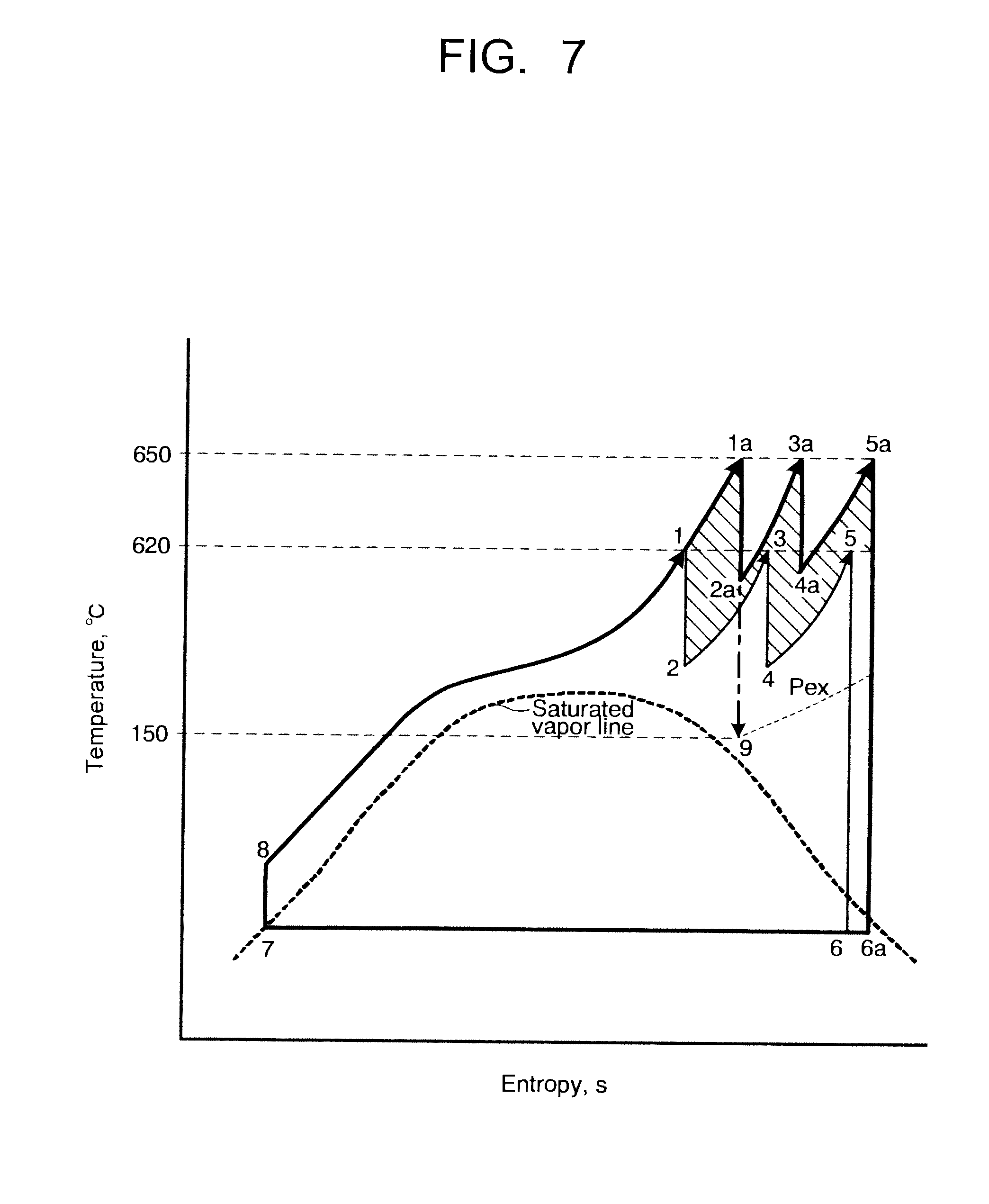
[0115] FIG. 7 is a diagram showing a T-s curve (temperature-entropy curve) of a steam condition change in the steam turbine power plant 12 according to the third embodiment of the invention. FIG. 7 also shows a condition change in a conventional two stage reheat cycle for comparison. There is shown an example that the temperature of the steam introduced into the superhigh-pressure turbine 36 in the steam turbine power plant 12 according to the third embodiment is determined to be 650.degree. C., and the temperature of the steam introduced into the superhigh-pressure turbine in a conventional steam turbine power plant is determined to be 620.degree. C. It is assumed in FIG. 7 that the expansion process in each turbine is adiabatic expansion in the same manner as in FIG. 3 and FIG. 5.
[0116] In the conventional steam turbine power plant, is indicated that 8.fwdarw.1 is an isobaric heating by the boiler, 1.fwdarw.2 is adiabatic expansion by the superhigh-pressure turbine, 2.fwdarw.3 is isobaric reheating by the reheater, 3.fwdarw.4 is adiabatic expansion by the high-pressure turbine, 4.fwdarw.5 is isobaric reheating by the reheater, and 5.fwdarw.6 is adiabatic expansion by the intermediate-pressure turbine and the low-pressure turbine. And, it is indicated that 6.fwdarw.7 is isothermal condensation by the condenser, and 7.fwdarw.8 is a pressure increase and a temperature increase by the water feed pump and the feed water heater.
[0117] Meanwhile, in the steam turbine power plant 12 of the third embodiment, the temperature of the steam introduced into the superhigh-pressure turbine 36 is higher than the temperature of the steam introduced into the superhigh-pressure turbine of the conventional steam turbine power plant, so that the adiabatic expansion in the superhigh-pressure turbine 36 becomes 1a.fwdarw.2a. The adiabatic expansion by the high-pressure turbine 22 becomes 3a.fwdarw.4a. And, the adiabatic expansion by the intermediate-pressure turbine 24 and the low-pressure turbine 25 becomes 5a.fwdarw.6a.
[0118] In FIG. 7, the area (area of the shaded portion in FIG. 7) surrounded by a steam condition value higher than the conventional steam condition value is an increase in energy which can be taken out as a work, namely an extent of a contribution to efficiency improvement by an increase in temperature.
[0119] The adiabatic expansion by the back-pressure turbine 27 is indicated by 2a.fwdarw.9, and the temperature of the steam discharged from the back-pressure turbine 27 is determined by pressure Pex of the discharged steam. For example, when the temperature of the steam discharged from the back-pressure turbine 27 is lower than the temperature (e.g., 150.degree. C.) of the steam required by the carbon dioxide recovery system 50, the pressure Pex of the steam discharged from the back-pressure turbine 27 is raised by closing the pressure regulating valve V2. Thus, the temperature of the steam discharged from the back-pressure turbine 27 can be raised to become closer to a predetermined temperature. When the flow rate of the steam introduced into the carbon dioxide recovery system 50 is lower than a predetermined flow rate, it can be made closer to the predetermined flow rate by increasing the opening degree of the flow rate regulating valve V1.
[0120] At this time, the flow rate of the extraction steam from the back-pressure turbine 27, which is supplied to the high-pressure feed water heater 34, is controlled by the ability of the high-pressure feed water heater 34 depending on a feed water flow rate (substantially proportional to the boiler load) and an extraction steam pressure and substantially proportional to the feed water flow rate similar to the prior art. In other words, the flow rate of the steam introduced into the back-pressure turbine 27 through the pipe 151 is a total of the flow rate of the steam discharged from the back-pressure turbine 27 and the flow rate of the extraction steam supplied to the high-pressure feed water heater 34. This total flow rate is substantially proportional to the feed water flow rate (boiler load).
[0121] Generally, the extraction steam flow rate is about 5% of the feed water flow rate per stage of the feed water heater. For example, when the steam extraction to the four stages of the high-pressure feed water heater 34 is made as shown in FIG. 6 and the flow rate of the steam introduced into the carbon dioxide recovery system 50 is determined to be 40% of the feed water flow rate, a steam flow rate of "40%+4 stages.times.5%=60%" is introduced into the back-pressure turbine 27. It is a steam flow rate sufficient to overcome a variation or low operability of an extraction steam pressure, which is proportional to a stage steam flow rate and caused because the load of the conventional back-pressure extraction turbine for driving the water feed pump described above is small to about 2% (about 15% of the feed water flow rate in terms of the drive steam flow rate) of the boiler load. And, since the flow rate of the steam for driving the back-pressure turbine 27 is substantially proportional to the feed water flow rate (namely, substantially proportional to the boiler load) in the steam turbine power plant 12 according to the third embodiment, the extraction steam pressure is substantially proportional to the boiler load. Therefore, the extraction steam pressure has the same property as that of a change of the extraction steam pressure of the normal steam turbine power plant, and a problem of operability is not produced.
[0122] By the above-described control, the output of the electric generator 35 for the back-pressure turbine 27 is controlled by adjusting the flow rate regulating valve V1 and the pressure regulating valve V2, and the output of the entire steam turbine power plant 10 is determined by a total of the electric generator 26 for the low-pressure turbine and the electric generator 35 for the back-pressure turbine 27. Therefore, it becomes possible to obtain a predetermined output by controlling the flow rate of the steam introduced into the high-pressure turbine by a steam control valve (not shown) to control the output of the electric generators 26 and 35. The output of the electric generator 35 is substantially proportional to that of the boiler load, so that it is also substantially proportional to the output of the electric generator 26 and excellent in controllability.
[0123] In a case where the steam turbine power plant 12 is operated with the steam introduced into the reboiler 120 blocked in order to make the exchange of the absorption liquid 90 of the carbon dioxide recovery apparatus 80, the flow rate regulating valve V1 is controlled such that the output of the back-pressure turbine 27 becomes a minimum output capable of performing a stable operation to adjust the flow rate of the steam introduced into the back-pressure turbine 27. And, a shutoff valve (not shown) disposed on the pipe 42 is closed to stop the steam from flowing into the carbon dioxide recovery apparatus 80. In addition, it is controlled to fully open the pressure regulating valve V2 to introduce the total amount of the steam discharged from the back-pressure turbine 27 into the low-pressure feed water heater 31.
[0124] As described above, the steam turbine power plant 12 according to the third embodiment uses the steam discharged from the superhigh-pressure turbine 36 to drive the back-pressure turbine 27 and can generate electricity by driving the electric generator 35 disposed on the back-pressure turbine 27. In addition, as energy necessary for the regeneration tower 70 of the carbon dioxide recovery apparatus 80, it is possible to use the steam having low exergy which has performed the expansion work by the back-pressure turbine 27. Thus, an energy loss can be suppressed, and high power generation efficiency can be obtained.
[0125] In addition, the steam extracted from the back-pressure turbine 27 can be made to have a temperature of 580.degree. C. or below. Therefore, as the material configuring the steam extraction pipe between the back-pressure turbine 27 and the high-pressure feed water heater 34 and the high-pressure feed water heater 34, the same material as the material such as carbon steel which has been used for them can be used. And, a thermal stress generated due to a difference between the temperature of the feed water flowing through the high-pressure feed water heater 34 and the temperature of the extraction steam guided to the high-pressure feed water heater 34 can be prevented from increasing.
[0126] While certain embodiments have been described, these embodiments have been presented by way of example only, and are not intended to limit the scope of the inventions. Indeed, the novel methods and systems described herein may be embodied in a variety of other forms; furthermore, various omissions, substitutions and changes in the form of the methods and systems described herein may be made without departing from the spirit of the inventions. The accompanying claims and their equivalents are intended to cover such forms or modifications as would fall within the scope and sprit of the inventions.
* * * * *
D00000
D00001
D00002
D00003
D00004
D00005
D00006
D00007
D00008
XML
uspto.report is an independent third-party trademark research tool that is not affiliated, endorsed, or sponsored by the United States Patent and Trademark Office (USPTO) or any other governmental organization. The information provided by uspto.report is based on publicly available data at the time of writing and is intended for informational purposes only.
While we strive to provide accurate and up-to-date information, we do not guarantee the accuracy, completeness, reliability, or suitability of the information displayed on this site. The use of this site is at your own risk. Any reliance you place on such information is therefore strictly at your own risk.
All official trademark data, including owner information, should be verified by visiting the official USPTO website at www.uspto.gov. This site is not intended to replace professional legal advice and should not be used as a substitute for consulting with a legal professional who is knowledgeable about trademark law.