Selective Catalytic Reduction Exhaust Aftertreatment System And Engine Incorporating The Same
Mital; Rahul ; et al.
U.S. patent application number 12/685016 was filed with the patent office on 2010-12-30 for selective catalytic reduction exhaust aftertreatment system and engine incorporating the same. This patent application is currently assigned to GM GLOBAL TECHNOLOGY OPERATIONS, INC.. Invention is credited to Jianwen Li, Rahul Mital.
| Application Number | 20100326059 12/685016 |
| Document ID | / |
| Family ID | 43379244 |
| Filed Date | 2010-12-30 |


| United States Patent Application | 20100326059 |
| Kind Code | A1 |
| Mital; Rahul ; et al. | December 30, 2010 |
SELECTIVE CATALYTIC REDUCTION EXHAUST AFTERTREATMENT SYSTEM AND ENGINE INCORPORATING THE SAME
Abstract
In one exemplary embodiment of the present invention, an exhaust aftertreatment system is disclosed. The system includes an oxidation catalyst (OC) that is configured to receive an exhaust gas flow from an engine. The system also includes an uncoated particulate filter (PF) that is configured to receive the exhaust gas flow from the OC. The system further also includes an exhaust fluid (EF) dosing device configured for dosing of an EF into the exhaust gas flow upstream of the uncoated PF. Still further, the system includes a selective catalyst reduction (SCR) catalyst that is configured to receive the exhaust gas flow from the uncoated PF, wherein the OC, uncoated PF and SCR catalyst comprise an exhaust aftertreatment system. A urea injector may be provided as the EF dosing device and arranged to inject urea, for example, into the exhaust gases upstream of the uncoated PF.
| Inventors: | Mital; Rahul; (Rochester Hills, MI) ; Li; Jianwen; (West Bloomfield, MI) |
| Correspondence Address: |
    Cantor Colburn LLP-General Motors
    20 Church Street,  22nd Floor
    Hartford
    CT
    06103
    US
|
| Assignee: | GM GLOBAL TECHNOLOGY OPERATIONS,
INC. Detroit MI |
| Family ID: | 43379244 |
| Appl. No.: | 12/685016 |
| Filed: | January 11, 2010 |
Related U.S. Patent Documents
| Application Number | Filing Date | Patent Number | ||
|---|---|---|---|---|
| 61220667 | Jun 26, 2009 | |||
| Current U.S. Class: | 60/297 ; 29/890; 60/299; 60/303 |
| Current CPC Class: | F01N 3/0222 20130101; F01N 3/2828 20130101; F01N 3/035 20130101; F01N 3/281 20130101; F01N 2610/03 20130101; F01N 2610/02 20130101; Y02T 10/12 20130101; Y10T 29/49345 20150115; F01N 3/103 20130101; F01N 13/0093 20140601; Y02T 10/24 20130101; F01N 13/009 20140601; F01N 13/0097 20140603; F01N 3/2066 20130101 |
| Class at Publication: | 60/297 ; 60/299; 60/303; 29/890 |
| International Class: | F01N 3/035 20060101 F01N003/035; F01N 3/10 20060101 F01N003/10; B21D 51/16 20060101 B21D051/16 |
Claims
1. An exhaust aftertreatment system, comprising: an oxidation catalyst (OC) that is configured to receive an exhaust gas flow from an engine; an uncoated particulate filter (PF) that is configured to receive the exhaust gas flow from the OC; an exhaust fluid (EF) dosing device configured for dosing of an EF into the exhaust gas flow upstream of the uncoated PF; and a selective catalytic reduction (SCR) catalyst that is configured to receive the exhaust gas flow from the uncoated PF, wherein the OC, EF dosing device, uncoated PF and SCR catalyst comprise an exhaust aftertreatment system.
2. The exhaust aftertreatment system of claim 1, further comprising a second OC that is configured to receive the exhaust gas flow from the SCR catalyst.
3. The exhaust aftertreatment system of claim 1, wherein the uncoated PF and SCR catalyst are housed in a single housing.
4. The exhaust aftertreatment system of claim 1, wherein the uncoated PF and SCR catalyst are each housed in a separate housing.
5. The exhaust aftertreatment system of claim 2, wherein the uncoated PF, SCR catalyst and second OC are housed in a single housing.
6. The exhaust aftertreatment system of claim 2, wherein the SCR catalyst and second OC are each located on a metal or ceramic substrate, or a combination thereof
7. The exhaust aftertreatment system of claim 6, wherein SCR catalyst and second OC are each located on a monolithic, flow-through substrate.
8. The exhaust aftertreatment system of claim 1, further comprising an HC dosing device located upstream of the OC.
9. The exhaust aftertreatment system of claim 1, wherein the EF dosing device comprises a urea injector.
10. An internal combustion engine and exhaust aftertreatment system, comprising: an internal combustion engine comprising an exhaust treatment system, the exhaust treatment system comprising: an oxidation catalyst (OC) that is configured to receive an exhaust gas flow from the engine; an uncoated particulate filter (PF) that is configured to receive the exhaust gas flow from the OC; an exhaust fluid (EF) dosing device configured for dosing of an EF into the exhaust gas flow upstream of the uncoated PF; and a selective catalytic reduction (SCR) catalyst that is configured to receive the exhaust gas flow from the PF.
11. The exhaust aftertreatment system for an internal combustion engine of claim 10, further comprising a second OC that is configured to receive the exhaust gas flow from the SCR catalyst.
12. The exhaust aftertreatment system for an internal combustion engine of claim 10, wherein the uncoated PF and SCR catalyst are housed in a single housing.
13. The exhaust aftertreatment system for an internal combustion engine of claim 10, wherein the uncoated PF and SCR catalyst are each housed in a separate metal housing.
14. The exhaust aftertreatment system for an internal combustion engine of claim 11, wherein the uncoated PF, SCR catalyst and second OC are housed in a single housing.
15. The exhaust aftertreatment system for an internal combustion engine of claim 11, wherein the SCR catalyst and second OC are each located on a separate metal or ceramic substrate, or a combination thereof.
16. The exhaust aftertreatment system for an internal combustion engine of claim 15, wherein the SCR catalyst and second OC are each located on the same monolithic, flow-through substrate.
17. The exhaust aftertreatment system for an internal combustion engine of claim 10, further comprising an HC dosing device located upstream of the OC.
18. The exhaust aftertreatment system for an internal combustion engine of claim 10, wherein the EF dosing device comprises a urea injector.
19. A method of making an exhaust aftertreatment system, comprising: providing an oxidation catalyst (OC) that is configured to receive an exhaust gas flow from an engine; fluidly connecting an uncoated particulate filter (PF) to the OC to receive the exhaust gas flow from the OC; fluidly connecting an exhaust fluid (EF) dosing device upstream of the uncoated PF for dosing of an EF into the exhaust gas flow; and fluidly connecting a selective catalytic reduction (SCR) catalyst to receive the exhaust gas flow from the uncoated PF, wherein the OC, EF dosing device, uncoated PF and SCR catalyst comprise an exhaust aftertreatment system.
20. The method of claim 19, further comprising fluidly connecting a second OC to receive the exhaust gas flow from the SCR catalyst.
Description
CROSS-REFERENCE TO RELATED APPLICATIONS
[0001] This application claims priority to provisional patent application Ser. No. 61/220,667 filed on Jun. 26, 2009, which is hereby incorporated by reference herein in its entirety.
FIELD OF THE INVENTION
[0002] Exemplary embodiments of the present invention are related to exhaust gas treatment systems, and, more specifically, to an exhaust gas treatment system for lean-burn internal combustion engines and vehicles incorporating the same.
BACKGROUND
[0003] Manufacturers of internal combustion engines must satisfy customer demands and meet various regulations for reduced emissions and improved fuel economy. One example of a way to improve fuel economy is to operate an engine at an air/fuel ratio that is lean (excess oxygen) of stoichiometry. Examples of lean-burn engines include compression-ignition (diesel) and lean-burn spark-ignition engines. However, while a lean-burn engine has improved fuel economy, they tend to have higher nitrogen oxides (NO.sub.X) emissions. The commercial application of lean-burn engines is limited due to a lack of effective methods to remove sufficient NO.sub.X from the lean exhaust stream before it exits the tail pipe to meet regulations. Thus, efficient reduction of NO.sub.X from lean-burn gasoline and diesel exhaust before it exits the tail pipe is important to meet future emission standards and improve vehicle fuel economy.
[0004] Reduction of NO.sub.X emissions from an exhaust stream including excess oxygen is a challenge for vehicle manufacturers. It is estimated that compliance with Bin 5 regulations in the United States may require an aftertreatment system for diesel and gasoline engines capable of 70-90% NO.sub.X conversion efficiency on the FTP (Federal Test Procedure) cycle based on currently anticipated engine-out NO.sub.X levels. Such conversion efficiency must be obtained at a variety of operating temperatures ranging between 200-550.degree. C. during various parts of the aforementioned FTP cycle or, for example, the US06 Federal Test Procedure.
[0005] Several potential aftertreatment systems have been proposed for vehicle applications. These systems employ various exhaust aftertreatment devices. One such aftertreatment system employs a urea selective catalyst reduction (SCR) catalyst and a NO.sub.X reductant, e.g., urea, that is injected upstream of the catalyst and is converted to ammonia that is used to reduce NO.sub.X to N.sub.2. Use of urea as a reductant necessitates a urea distribution infrastructure and an on-vehicle monitoring system for this secondary fluid, and may have potential problems in cold weather climates due to the relatively high freezing point (-12.degree. C.) of the urea solution. NO.sub.X storage catalysts typically require large catalyst volumes, large amounts of platinum-group metals and low sulfur fuel for efficient storage operation. Such systems require periodic catalyst regeneration involving fuel injection or injection of reductants to regenerate the storage material of the catalyst.
[0006] While systems that employ SCR catalysts have been used for NO.sub.X reduction in exhaust gas flow streams having excess oxygen, packaging of the various catalysts has been problematic, particularly in relatively smaller vehicles having relatively shorter wheelbases, due the reduced space available to package the desired combinations of catalysts. For example, in some of the smaller heavy duty vehicles, it is desirable to package the SCR last where it is farthest from the engine and the exhaust system operating temperatures are lowest, in order to minimize thermal degradation of the SCR catalyst materials and thereby maximize the operating life of the SCR catalyst. While this arrangement is desirable, there is generally not enough room to package the SCR last while also providing the needed mixing length for conversion of the injected urea into ammonia, particularly if the system also employs one or more additional exhaust treatment devices for the reduction of NO.sub.X or oxidation or reduction of other exhaust constituents, including carbon monoxide (CO), various hydrocarbons (HC), particulate matter (PM) and the like.
[0007] Therefore, it would be desirable to develop exhaust aftertreatment systems that provide the needed NO.sub.X conversion under excess oxygen (lean burn) conditions using an SCR catalyst, and that can be packaged on vehicles having relatively short wheelbases and small space envelopes. It would also be desirable to locate the SCR last while also including other exhaust treatment devices within the space available on the vehicle while providing the necessary NO.sub.X reduction efficiency.
SUMMARY OF THE INVENTION
[0008] In one exemplary embodiment of the present invention, an exhaust aftertreatment system is disclosed. The system includes an oxidation catalyst (OC) that is configured to receive an exhaust gas flow from an engine. The system also includes an uncoated particulate filter (PF) that is configured to receive the exhaust gas flow from the OC. The system further also includes an exhaust fluid (EF) dosing device configured for dosing of an EF into the exhaust gas flow upstream of the uncoated PF. Further, the system includes an SCR catalyst that is configured to receive the exhaust gas flow from the PF, wherein the OC, uncoated PF, EF dosing device and SCR catalyst comprise an exhaust aftertreatment system.
[0009] In another exemplary embodiment of the present invention, an internal combustion engine and exhaust aftertreatment system is disclosed. The internal combustion engine includes an exhaust aftertreatment system. The exhaust aftertreatment system includes an OC that is configured to receive an exhaust gas flow from the engine. The exhaust aftertreatment system also includes an uncoated PF that is configured to receive the exhaust gas flow from the OC. The system further also includes an exhaust fluid (EF) dosing device configured for dosing of an EF into the exhaust gas flow upstream of the uncoated PF. Still further, the system also includes an SCR catalyst that is configured to receive the exhaust gas flow from the PF wherein the OC, uncoated PF, EF dosing device and SCR catalyst comprise an exhaust aftertreatment system.
[0010] In yet another exemplary embodiment of the present invention, a method of making an exhaust aftertreatment system is disclosed. The method includes providing an OC that is configured to receive an exhaust gas flow from an engine. The method also includes fluidly connecting an uncoated PF to the OC to receive the exhaust gas flow from the OC. The method further includes fluidly connecting an EF dosing device upstream of the PF for dosing an EF into the exhaust gas flow. Further, the method includes fluidly connecting an SCR catalyst to receive the exhaust gas flow from the PF, wherein the OC, EF dosing device, PF and SCR catalyst comprise an exhaust aftertreatment system.
BRIEF DESCRIPTION OF THE DRAWINGS
[0011] Other features, advantages and details appear, by way of example only, in the following description of embodiments, the description referring to the drawings in which:
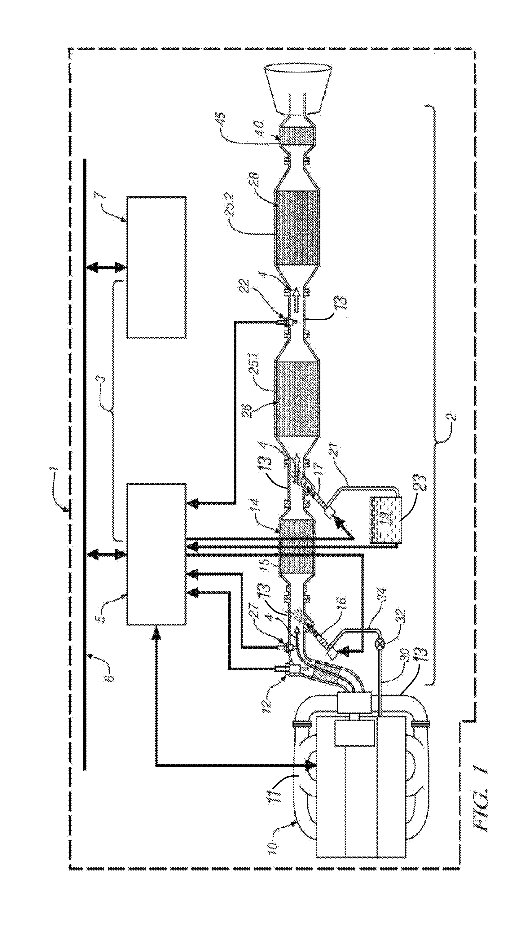
[0012] FIG. 1 is a schematic illustration of an exemplary embodiment of an internal combustion engine and exhaust gas treatment system as disclosed herein; and;
[0013] FIG. 2 is a schematic illustration of a second exemplary embodiment of an internal combustion engine and exhaust gas treatment system as disclosed herein.
DESCRIPTION OF THE EMBODIMENTS
[0014] Referring now to FIGS. 1 and 2, schematic diagrams depict exemplary embodiments of an internal combustion engine 10 that is particularly suitable for use in many types of motorized vehicles 1, such as automobiles, light trucks, marine vehicles, ATVs and the like, as well as numerous fixed installation applications, such as generators, pumps and the like. Engine 10 includes an exhaust aftertreatment system 2, including a plurality of exhaust aftertreatment devices. These exemplary embodiments of exhaust aftertreatment system 2 include an OC 14, such as a diesel oxidation catalyst, that is used to oxidize certain constituents of exhaust gas flow 4. OC 14 is located upstream of PF 26, such as a diesel particulate filter (DPF), that is used to filter PM from the exhaust gas flow 4. OC 14 may also be used for regeneration of PF 26 by generation of heat for oxidation of the PM, as described herein. Exhaust aftertreatment system 2 also includes a urea selective catalyst reduction (SCR) catalyst 28 located downstream of an uncoated PF 26. Optionally, system 2 may also include a second OC 40 downstream of SCR catalyst 28 to oxidize any remaining HC and reduce the possibility of HC, ammonia or CO slip through the system, i.e. passage through the system without being converted. The physical spacing of OC 14 and SCR catalyst 28 by the uncoated PF 26 provides greater distance over which the urea may vaporize and mix and be converted to ammonia through thermolysis and hydrolysis reactions, thereby improving the conversion efficiency of the urea and providing sufficient opportunity for this reaction to occur, thus enhancing the NO.sub.X conversion ability of SCR catalyst 28. The heat resulting from the oxidation reactions in OC 14 further facilitates the urea conversion. The location of OC 14 just upstream of PF 26 increases the efficiency of usage of post-injected fuel, since post-injected fuel is used only for generating heat, and this arrangement places OC 14 in close proximity to PF 26, thereby reducing heat losses from the fuel usage and increasing the efficiency of PF 26, as well as engine 10 or vehicle 1, or both of them, in cases where the fuel is drawn from the vehicle fuel tank.
[0015] Exhaust aftertreatment system 2 may be used with any internal combustion engine and engine control system 3. An exemplary engine 10 and control system 3 includes a conventional four-cycle diesel, gasoline or natural gas fueled internal combustion engine and electronic engine control module (ECM) 5. The engine 10 may include a compression-ignition or diesel engine having an operating regime such that it is primarily a lean-burn engine and is operated on an air/fuel mixture where the amount of fuel is lower or leaner than the stoichiometric amount required for combustion, or from another perspective, where the oxygen exceeds the stoichiometric amount. Alternately, engine 10 may include an engine employing any one of a number of engine control strategies that operate lean of stoichiometry, e.g., homogeneous-charge compression-ignition engines and lean-burn spark-ignition engines. Engine 10 includes one or more reciprocating pistons attached to a crankshaft, which is operably attached to a driveline or powertrain of vehicle 1 to deliver tractive torque to the driveline. During operation, internal combustion processes in engine 10 generate an exhaust gas feedstream or flow that travels in the direction illustrated by arrow 4 and contains regulated constituents as combustion by-products, and that must be transformed by the aftertreatment system prior to release from the system 2, such as to an external environment. The constituents of exhaust gas flow 4 produced by engine 10 under lean combustion conditions include HC, CO, NO.sub.X, and PM, among others.
[0016] Exhaust aftertreatment system 2 is an integrated system intended to treat the regulated constituents of the exhaust gas flow 4 to produce a flow that includes unregulated constituents, or regulated constituents in amounts that may be released from the system to the external environment, such as by reducing amounts of the regulated constituents to acceptable levels or by chemically converting them to unregulated materials that may be released. An exhaust manifold 11, or manifolds, and associated conduits 13 entrain and direct the exhaust gas flow 4 to and through the exhaust aftertreatment system 2. Referring to FIGS. 1-2, the exhaust aftertreatment systems 2 described herein, including the components or devices thereof described herein, employ technologies having various capabilities for treating the constituent elements of the exhaust gas feedstream, including oxidation, selective catalytic reduction, HC (e.g., fuel) or reductant (e.g., urea) dosing and particulate filtering, as further described herein. The devices are fluidly and operably connected in series and in fluid communication with one another using known pipes or conduits 13 and connectors to contain and channel the exhaust gas flow 4 through exhaust aftertreatment system 2.
[0017] Referring again to the exemplary embodiments of FIGS. 1 and 2, the OC 14 is in fluid communication with the engine 10 and, with reference to the exhaust gas flow 4, is located downstream from engine 10 and is configured to oxidize certain constituents of the exhaust gas flow 4 to produce unregulated by-products or constituents that are adapted for further treatment in other components of exhaust aftertreatment system 2, as described herein. Generally, the OC 14 is a flow-through device, as described herein, that consists of a metal or ceramic monolith or substrate having a honeycomb-like structure that includes a plurality of generally parallel, longitudinally-extending, interconnected cells that provide a network comprising a plurality of flow channels for receiving exhaust gas flow 4 and are separated by a corresponding network of cell walls. The substrate has a large surface area along the cell walls. The cell walls have a washcoat that includes a porous ceramic matrix with a surface that is coated with a catalytically active amount of a Pt group metal catalyst. Suitable platinum group metals include Pt, Pd, Rh, Ru, Os or Ir, or a combination thereof. Of these, Pt or Pd, or combinations thereof, including alloys thereof, are particularly useful. Those that include both Pt and Pd are particularly useful, such as those having Pt:Pd ratios of about 2:1 to about 4:1. As the exhaust gas flow 4 traverses the length of the OC 14, particularly the flow channels and the washcoated cell walls, the platinum group metal catalyst catalyzes the oxidation of CO to CO.sub.2, as well as catalyzing the oxidation of various HC, including gaseous HC's and liquid HC particles, including unburned fuel or oil, or fuel or other HC reactants that are introduced into exhaust gas aftertreatment system to form CO.sub.2 and H.sub.2O, thereby reducing harmful emissions. In one configuration, during an advanced combustion operation of the engine, the control system 3, including ECM 5, may be used to cause combustion resulting in a higher level of HC in the exhaust gas flow 4 than is generated during normal combustion. The OC 14 is configured to catalyze the decomposition of at least a portion of the increased amounts of HC in order to reduce, or alternately to prevent, the HC in the exhaust gas flow from reaching the SCR catalyst 28 and poisoning this device by reducing its ability to catalyze NO.sub.X, or from reaching the external environment by release from the exhaust aftertreatment system 2.
[0018] The OC 14, such as a diesel oxidation catalyst (DOC) in the case of an exhaust aftertreatment system 2 for a diesel engine 10, may be configured to convert various regulated exhaust constituents to other regulated or unregulated exhaust constituents through oxidation. For example, the OC 14 may be configured to oxidize HC to carbon dioxide (CO.sub.2) and water (H.sub.20), convert CO to carbon dioxide (CO.sub.2) convert sulfur dioxide (SO.sub.2) to sulfur trioxide (SO.sub.3) and/or sulfuric acid (H.sub.2SO.sub.4) and convert nitrogen oxide (NO) to nitrogen dioxide (NO.sub.2), or otherwise. Exemplary oxidation reactions contemplated with the OC 14 are provided below:
HC+O.sub.2.dbd.CO.sub.2+H.sub.20 (1)
CO+ 1/20O.sub.2.dbd.CO.sub.2 (2)
2SO.sub.2+O.sub.2.dbd.2SO.sub.3 (3)
SO.sub.3+H.sub.2O.dbd.H.sub.2SO.sub.4 (4)
NO+ 1/20O.sub.2.dbd.NO.sub.2 (5)
[0019] It should be appreciated that the OC 14 may be configured to perform any one of the above conversions, combinations of the above conversions, or even all of the above conversions, depending on the reactant compounds and their concentrations found in the exhaust gas flow 4, the temperature of OC 14, and the platinum group metals selected as the catalyst. Other oxidations are contemplated as well, such as oxidation of aldehydes, polycyclic aromatic hydrocarbons or otherwise. Further, the reactions in OC 14 may be used to reduce the odor of certain emission components.
[0020] OC 14 may be housed within a separate housing 15, including a metal housing, such as a metal can having an inlet opening and outlet opening, or otherwise, configured for providing support and directing fluid flow to the OC 14, as shown in FIGS. 1 and 2. The housing 15 may comprise any suitable shape or size including a cylindrically shaped compartment. In an exemplary embodiment, housing 15 for OC 14 was generally cylindrical in shape having a volume of about 5.0 liters with a tapered inlet and outlet and associated mounting flanges to size the cylinder wall down for engagement with and fluid coupling to respective exhaust conduits with their associated mounting flanges. The compartment, as well as other compartments described herein, further may include attachment features, such as a cylindrical inlet pipe located proximate an inlet opening and a cylindrical outlet pipe located proximate an outlet opening of the compartment for fluid coupling of OC 14 to an exhaust pipe and/or another component of the exhaust aftertreatment system 2. It should be appreciated that OC 14, including the housing 15, may include one or more additional components for facilitating operation of OC 14, or exhaust aftertreatment system 2, or control system 3, including, but not limited to, various gas or temperature sensors, injectors (urea or fuel injectors) or otherwise. Such additional features may be particularly advantageous for monitoring characteristics of the exhaust gas flow 4, such as the flow rate of certain emission constituents (e.g., particulate matter or otherwise), which may be particularly advantageous for determining the necessity of initiating certain system processes, such as, for example, the regeneration of PF 26 or SCR catalyst 28.
[0021] PF 26 is a wall-flow-device that consists of a ceramic monolith or substrate having a honeycomb-like structure that includes a plurality of generally parallel, longitudinally-extending, interconnected cells that provide a network comprising a plurality of flow channels for exhaust gas flow 4 and are separated by a corresponding network of porous cell walls. The substrate has a large surface area along the cell walls. Alternating adjacent cells have one of the inlet or outlet plugged such that an alternating array of inlets is plugged with inlets of the immediately adjacent cells being open, and an alternating array of outlets is plugged with outlets of the immediately adjacent cells being open. The structure has open pores in the cell walls. Thus, the exhaust gas flow 4 passes into the plurality of inlets and is forced through the porous cell walls and into the adjacent outlet cells where it then flows out the plurality of unplugged outlets. The pores permit the gaseous constituents to pass through the cell walls while the PM is entrapped within the pores, thereby providing the PM filtering action of PF 26. PF 26 may have a predetermined amount of porosity selected to selectively filter PM within the exhaust gas flow 4 over a range of predetermined exhaust gas flow rates within exhaust aftertreatment system 2, with the pore size selected to be smaller than a predetermined particle size of the PM that exists within exhaust gas flow 4. In an exemplary embodiment, the average pore size is selected to be smaller than the average size of the PM particles. For example, in gasoline fueled engines, the average particle size of the PM is generally smaller than the average particle size of PM in diesel engines, hence the pore size of PF 26 used in gasoline engines may be selected to be smaller than the average pore size of PF 26 used in diesel engines (e.g., DPF). Any suitable pore size may be used. Any suitable material may be used for PF 26, including various high temperature ceramic materials. In an exemplary embodiment, PF 26 may include a ceramic material comprising cordierite or alumina, or a combination thereof. In an exemplary embodiment, PF 26 is uncoated, that is, it is not treated with a material that is configured to catalyze the oxidation or reduction of the constituents of exhaust gas flow 4.
[0022] The SCR catalyst 28 may be provided, for example, as a washcoat disposed on a ceramic flow-through monolith or substrate having a honeycomb-like structure that includes a plurality of generally parallel, longitudinally-extending, interconnected cells that provide a network comprising a plurality of flow channels for exhaust gas flow 4 and are separated by a corresponding network of cell walls. The substrate has a large surface area along the cell walls. The washcoat includes a reduction catalyst disposed on a ceramic matrix. The washcoat may be disposed along the cell walls in any suitable configuration. For example, it may be located proximate the cell inlets or the cell outlets, or a combination of them, or along the entire length of the cells. The washcoat includes a porous matrix with a surface that is coated with a catalytically active amount of a suitable reduction catalyst. The ceramic wall-flow monolith may be made from any suitable ceramic, including cordierite or alumina or the like.
[0023] PF 26 and SCR catalyst 28 are adapted to provide reduction of NO.sub.X (SCR catalyst 28) and collection and conversion of PM (PF 26) over most of the operating temperature range of exhaust aftertreatment system 2 and engine 10, including typical exhaust treatment system operating temperatures of from about 302.degree. F. (about 150.degree. C.) to about 1202.degree. F. (about 650.degree. C.). PF 26 is uncoated and is configured to filter soot over the entire operating temperature range of engine 10, including, but not limited to, typical ambient vehicle storage/starting temperatures from about -40.degree. F. (about -40.degree. C.) to about 120.degree. F. (about 49.degree. C.) to operating temperatures up to about 1292.degree. F. (about 700.degree. C.). Passive regeneration of PF 26 and oxidation of the soot particles occurs in the presence of NO.sub.X over the temperature range of 482.degree. F. (250.degree. C.) to about 842.degree. F. (450.degree. C.), whereas active regeneration and oxidation of the soot particles occurs in the presence of O.sub.2 at temperatures of about 500.degree. C. or more, and more preferably over the temperature range of about 1112.degree. F. (600.degree. C.) to about 1202.degree. F. (650.degree. C.).
[0024] The SCR catalyst washcoat includes a porous ceramic matrix with a surface that is coated with a catalytically active amount of a base metal catalyst, i.e., an amount sufficient to catalyze the desired chemical reactions. Suitable base metal catalysts include copper (Cu), chromium (Cr) or iron (Fe), or a combination thereof, including alloys and compounds thereof. The porous matrix may include any suitable porous matrix. Suitable porous matrices include various zeolites. In the case of Cu catalysts, a suitable zeolite is one known commercially as ZSM-5. The use of a base metal catalyst allows conversion of the nitrogen oxides without the use of precious metals. SCR catalyst 28 utilizes ammonia to reduce NO.sub.X. For example, in an exemplary embodiment, a dosing device, such as urea dosing device 17, is provided upstream from uncoated PF 26 for introducing an exhaust fluid (EF), and in the case of exhaust fluids used with diesel exhaust after treatment systems a diesel EF (DEF), such as urea, to the exhaust gas flow stream 4, such as through introduction of a urea solution into exhaust gas flow 4. The EF is introduced upstream a sufficient distance from uncoated PF 26 to permit the fluid, e.g. a urea solution, to react in the exhaust gas flow 4 to form ammonia prior to entering SCR catalyst 28. Below are exemplary conversion chemical reactions contemplated with SCR catalyst 28:
[0025] Urea decomposition:
CO(NH.sub.2).sub.2+H.sub.2O.fwdarw.2NH.sub.3+CO.sub.2 (6)
[0026] NO.sub.X reduction reations in SCR catalyst 28:
6NO+4NH.sub.3.fwdarw.5N.sub.2+6H.sub.2O (7)
4NO+4NH.sub.3+O.sub.2.fwdarw.4N.sub.2+6H.sub.2O (8)
6NO.sub.2+8NH.sub.3.fwdarw.7N.sub.2+12H.sub.2O (9)
2NO.sub.2+4NH.sub.3+O.sub.2.fwdarw.3N.sub.2+6H.sub.2O (10)
NO+NO.sub.2+2NH.sub.3.fwdarw.2N.sub.2+3H.sub.2O (11)
[0027] It should be appreciated that the SCR catalyst 28 may be configured to perform any one of the above conversions, or combinations of the above conversions, including all of the above conversions. SCR catalyst 28 begins to function as described above at an operating temperature of at about 356.degree. F. (180.degree. C.), and may be more preferably operated in the range of about 482.degree. F. (250.degree. C.) to about 1022.degree. F. (550.degree. C.).
[0028] Referring to FIG. 2, PF 26 and SCR catalyst 28 may be housed, for example, within a single housing 25, such as a metal can, configured to provide support and direct the exhaust gas flow 4 into PF 26 and out of SCR catalyst 28. The housing 25 may have any suitable shape or size including a cylindrical shape. The housing 25 may also include attachment features located proximate to an inlet opening, such as an inlet pipe, and an outlet opening, such as an outlet pipe, for fluid coupling of housing 25 to an exhaust pipe and/or other component of the exhaust aftertreatment system 2. It should be appreciated that housing 25, may include one or more additional components for facilitating operation of the exhaust aftertreatment system 2, including, but not limited to, various sensors, dosing devices (urea or fuel injectors) or otherwise. Such additional features may be particularly advantageous for monitoring characteristics of the exhaust gas flow 4, such as the amounts or flow rates of certain emission constituents, which are particularly advantageous for control of the exhaust aftertreatment system 2, including regeneration of PF 26.
[0029] Exhaust aftertreatment system 2 may optionally also include singly, or in combination, additional exhaust aftertreatment devices, including catalyzed or uncatalyzed particulate filters, additional oxidation catalysts, catalyzed soot filters, soot filters, NO.sub.X traps, NSR catalysts, partial hydrocarbon oxidation catalysts, air pumps, external heating devices, precious metal catalysts, sulfur traps, phosphorous traps, PO.sub.X reformers and the like. Each of the additional exhaust aftertreatment devices employs technologies having various capabilities for treating the constituent elements of the exhaust gas flow 4. These devices may be fluidly connected in series or parallel using known pipes, conduits and connectors. In an exemplary embodiment, as shown in FIGS. 1 and 2, exhaust aftertreatment system 2 may include a second OC 40 to ensure the oxidation of certain constituents in exhaust gas flow 4 and prevent their release from the system, including unburned HC, ammonia, urea or CO. Second OC 40 may be housed in a separate housing 45 (FIG. 1), such as that described above for OC 14, or alternately, may be housed together with SCR 28, or PF 26 and SCR catalyst 28, in a single housing 25 (FIG. 2).
[0030] Referring to FIG. 1, uncoated PF 26 and SCR catalyst 28 may also may be housed, for example, within separate housings 25.1, 25.2 respectively, such as metal cans, configured to provide support and direct the exhaust gas flow 4 into, through and out of these devices. The housings 25 may have any suitable shape or size including a cylindrical shape as described above in conjunction with housing 15. In an exemplary embodiment, housings 25.1 (PF 26) and 25.2 (SCR catalyst 28) were generally cylindrical in shape having volumes of about 8.7 liters and 13.2 liters, respectively, with tapered inlets and outlets to size the cylinder wall down for engagement with and fluid coupling to respective exhaust conduits. Housings 25.1 and 25.2 may each also include attachment features located proximate to an inlet opening, such as an inlet pipe, and an outlet opening, such as an outlet pipe, for fluid coupling of the devices to an exhaust pipe and/or other component of the exhaust aftertreatment system 2. It should be appreciated that housings 25.1 and 25.2 may include one or more additional components for facilitating operation of the exhaust aftertreatment system 2, including, but not limited to, various sensors, dosing devices (urea or fuel injectors) or otherwise.
[0031] The aftertreatment system includes sensing devices and systems that are signally connected to and in signal communication with control system 3, including ECM 5. The sensing devices may include a NO.sub.X sensor 12 operative to sense exhaust gases exiting the engine 10, a temperature sensor 27 operative to measure temperature of exhaust gases or a pressure sensor (not shown) to sense restriction of the porous passageways of cell walls of PF 26 by accumulation of PM. The NO.sub.X sensor 12 preferably comprises a sensor operative to generate an electrical signal correlatable to a parametric value for NO.sub.X concentration in the exhaust gas flow 4, and further operative to generate a second electrical signal correlatable to a parametric value for air/fuel ratio of the exhaust gas feedstream, from which oxygen content can be determined. The exhaust gas sensing device 22 may optionally include a second NO.sub.X sensor, operative to generate an electrical signal correlatable to a parametric value for NO.sub.X concentration in the exhaust gas feedstream, a temperature sensor or a pressure sensor, or a combination thereof. Alternately, NO.sub.X sensor 12 can comprise a virtual sensing device, wherein NO.sub.X concentration in the exhaust gas flow 4 is determined based upon engine operating conditions, which is a known technique.
[0032] The exhaust aftertreatment system 2 optionally includes a HC dosing device 16 for injecting a controlled amount of HC reductant upstream of OC 14. An exemplary HC dosing device includes a fuel injector, such as a diesel fuel injector in the case where engine 10 is a diesel engine, for injecting diesel fuel into exhaust gas flow 4. In an exemplary embodiment, the fuel line 30 from engine 10 provides pressurized fuel to a controllable pressure regulator device 32, such as a valve, the output of which is fluidly connected through conduit 34 to the HC dosing device 16. The HC dosing device 16 and pressure regulator device 32 are both operably connected to and in signal communication with control system 3, including ECM 5, which is adapted to control timing and quantity (e.g., mass flow) of HC injection, typically in the form of vehicle fuel, to the exhaust gas flow 4. Alternately, hydrocarbons from a hydrocarbon reservoir (not shown) or reformer device (not shown) may be used.
[0033] Referring to FIGS. 1 and 2, in exemplary embodiments, exhaust aftertreatment system 2 also includes an exhaust fluid (EF) dosing device 17, such as, for example, a urea injector, for injecting a controlled amount of EF 19 as a reductant upstream of the uncoated PF 26 from an EF reservoir 23 through conduit 21. As used herein, the term EF includes urea in all forms, including aqueous solutions, and may also include the use of ammonia (NH.sub.3) as a reductant, since the urea decomposes to produce ammonia as a reaction by-product, and it is the ammonia that is used as a reactant species in the catalytic reactions that occur in SCR catalyst 28. It may also include other materials that can be used to provide ammonia directly for injection into exhaust gas flow 4, or that provide ammonia, either directly or indirectly, upon injection into exhaust gas flow 4. An example of a suitable EF reservoir 23 is a urea tank. The EF dosing device 17 is operably connected to and in signal communication with ECM 5, which is adapted to control timing and quantity of EF 19 injection into the exhaust gas flow 4. When urea is used as the reductant, injection should occur sufficiently upstream from uncoated PF 26 to enable the decomposition of the urea to ammonia prior to entry into SCR catalyst 28.
[0034] The control system 3 preferably comprises a distributed control module architecture including a plurality of control modules adapted to provide coordinated control of the various vehicle systems including the powertrain system described herein. The control system is operable to monitor inputs from sensing devices, synthesize pertinent information, and execute algorithms to control various actuators to meet operator demands and achieve control targets, including such parameters as fuel economy, emissions, performance, drivability, and protection of hardware. The distributed controller architecture includes ECM 5, and User Interface (UI) 7 which is operably connected to and in signal communication with other devices through which a vehicle operator typically controls or directs operation of the vehicle and powertrain. Devices through which a vehicle operator provides input to the UI 7 typically include an accelerator pedal, a brake pedal, transmission gear selector, and, vehicle speed cruise control. Each of the aforementioned control modules and devices communicate with other control modules, devices, sensors, and actuators via a high-speed local area network (LAN) bus, shown generally as item 6. The LAN bus 6 allows for structured communication of control parameters and commands between the various processors, control modules, and devices. The specific communication protocol utilized is application-specific. The LAN bus and appropriate protocols provide for robust messaging and multi-control module interfacing between the aforementioned control modules and other control modules providing functionality such as antilock brakes, traction control, and vehicle stability.
[0035] The ECM 5 comprises a central processing unit signally electrically connected to volatile and non-volatile memory devices via data buses. The ECM 5 is operably attached to and in signal communication with sensing devices and other output devices to monitor and control operation of the engine 10 and exhaust aftertreatment system 2, as shown. The output devices preferably include subsystems necessary for proper control and operation of the engine, including, by way of example, an air intake system, a fuel injection system, a spark-ignition system (when a spark-ignition engine is used, e.g., a homogeneous charge compression ignition engine), an exhaust gas recirculation (EGR) system, and an evaporative control system. The engine sensing devices include devices operable to monitor engine operation, external conditions, and operator command, and are typically signally attached to the ECM 5 via wiring harnesses.
[0036] Algorithms stored in the non-volatile memory devices are executed by the central processing unit and are operable to monitor inputs from the sensing devices and execute engine control and diagnostic routines to control operation of the engine, using preset calibrations. Use of the ECM 5 to control and diagnose operation of various aspects of the internal combustion engine 10 is well known to one skilled in the art. However, the ECM 5 may be adapted to exploit the unique advantages of exhaust aftertreatment system 2 as described herein, to maximize the reduction of NO.sub.X under various operating regimes of engine 10, and also to maintain acceptable levels of NO.sub.X reduction during operation of vehicle 1 and engine 10, including during regeneration of PF 26 or SCR catalyst 28.
[0037] The engine 10 and exhaust aftertreatment system 2 provide a combination where the performance of the exhaust aftertreatment system is not constrained due to space limitation on the vehicle which can be provided at a cost competitive with existing treatment systems with a NO.sub.X conversion efficiency sufficient to meet Bin 5 and FTP cycle tailpipe regulations. In many existing designs, although it would be desirable, there is not enough room to package the SCR last while providing sufficient mixing length for DEF (e.g., urea) injection. These include, for example, short wheelbase, heavy-duty trucks that require the use of exhaust treatment devices that are capable of processing significant exhaust volumes, but have limited space in which to package the necessary exhaust treatment devices between the axles. As an example, the exhaust aftertreatment system 2 of this invention enables the packaging of a 5 liter OC 14, a 8.7 liter uncoated DPF 26 and a 13.2 liter SCR catalyst 28 forward of the rear axle. The exhaust aftertreatment system 2 of this invention provides such an aftertreatment system, where SCR catalyst 28 is located downstream of PF 26 within the space envelope available on the vehicle and without compromising NO.sub.X conversion efficiency. Packaging SCR catalyst 28 after PF 26 has the advantage that it would see lower exhaust temperatures under all operating conditions including regenerations, particularly as compared to other systems where the SCR is upstream of the DPF in a single can. The wall flow substrate of PF 26 provides the mixing environment needed to ensure NH.sub.3 uniformity at the face of the SCR catalyst 28. PF 26 also provides some NH.sub.3 storage capability in the uncoated wall-flow substrate, which will also enhance the NO.sub.X reduction capability of SCR catalyst 28. PF 26 will be closer to the engine which will be better for thermal management, particularly the retention of heat for use in PF 26 to decompose PM. The NO.sub.X will all react first with soot providing an improved catalytic reduction temperature (CRT) effect, resulting in longer regeneration intervals, improved fuel economy and PF durability. In addition, the use of second OC 40 downstream of SCR catalyst 28 can be added to control any HC, urea, ammonia or CO slip. Since PF 26 has no washcoat or platinum group metals, the associated cost saving from PF 26 can be used, for example, to provide second OC 40, without increasing the cost of exhaust aftertreatment system 2, relative to conventional exhaust aftertreatment systems. The need for urea mixers in exhaust conduits 13 will be minimized in this arrangement due to the space available for conversion of urea prior to reaching SCR catalyst 28 and the mixing effect realized from the wall-flow substrate of PF 26, which will result in further reductions of cost relative to conventional aftertreatment systems. The back pressure due to the wall-flow substrate of PF 26 provides high flow uniformity of urea/ammonia at the inlet of PF 26. Since exhaust gas flow 4 is forced through the substrate walls, this provides sufficient opportunity for the EF to mix even further and so by the time it will reach the SCR catalyst 28 inlet, the NH.sub.3 distribution will be substantially homogeneous.
[0038] While the invention has been described with reference to exemplary embodiments, it will be understood by those skilled in the art that various changes may be made and equivalents may be substituted for elements thereof without departing from the scope of the invention. In addition, many modifications may be made to adapt a particular situation or material to the teachings of the invention without departing from the essential scope thereof. Therefore, it is intended that the invention not be limited to the particular embodiments disclosed as the best mode contemplated for carrying out this invention, but that the invention will include all embodiments falling within the scope of the present application.
* * * * *
D00000
D00001
D00002
XML
uspto.report is an independent third-party trademark research tool that is not affiliated, endorsed, or sponsored by the United States Patent and Trademark Office (USPTO) or any other governmental organization. The information provided by uspto.report is based on publicly available data at the time of writing and is intended for informational purposes only.
While we strive to provide accurate and up-to-date information, we do not guarantee the accuracy, completeness, reliability, or suitability of the information displayed on this site. The use of this site is at your own risk. Any reliance you place on such information is therefore strictly at your own risk.
All official trademark data, including owner information, should be verified by visiting the official USPTO website at www.uspto.gov. This site is not intended to replace professional legal advice and should not be used as a substitute for consulting with a legal professional who is knowledgeable about trademark law.