Shoe Protector For Skateboarding Applications
ESPOSITO; Marcelo F. ; et al.
U.S. patent application number 12/825053 was filed with the patent office on 2010-12-30 for shoe protector for skateboarding applications. Invention is credited to Marcelo F. ESPOSITO, Mark M. TAKAHASHI.
| Application Number | 20100325922 12/825053 |
| Document ID | / |
| Family ID | 43379179 |
| Filed Date | 2010-12-30 |
| United States Patent Application | 20100325922 |
| Kind Code | A1 |
| ESPOSITO; Marcelo F. ; et al. | December 30, 2010 |
SHOE PROTECTOR FOR SKATEBOARDING APPLICATIONS
Abstract
A shoe protector as presented herein can be used to protect a shoe from damage caused when performing skateboarding tricks such as an ollie. The shoe protector includes a main body section shaped and sized to cover a portion of a shoe, the main body section having a tab formed in its upper section. The shoe protector also includes a plurality of shoelace holes formed in the tab, the shoelace holes being sized, shaped, and spaced apart to accommodate a shoelace pattern of the shoe, and an outer flap coupled to the main body section. The outer flap covers the shoelace holes, and the outer flap has the same perimeter and outline as an underlying portion of the tab.
| Inventors: | ESPOSITO; Marcelo F.; (Oceanside, CA) ; TAKAHASHI; Mark M.; (San Diego, CA) |
| Correspondence Address: |
    Mark Takahashi
    12487 Cavallo Street
    San Diego
    CA
    92130
    US
|
| Family ID: | 43379179 |
| Appl. No.: | 12/825053 |
| Filed: | June 28, 2010 |
Related U.S. Patent Documents
| Application Number | Filing Date | Patent Number | ||
|---|---|---|---|---|
| 61221649 | Jun 30, 2009 | |||
| Current U.S. Class: | 36/72R |
| Current CPC Class: | A43C 13/00 20130101; A43B 5/16 20130101 |
| Class at Publication: | 36/72.R |
| International Class: | A43B 13/22 20060101 A43B013/22 |
Claims
1. A shoe protector comprising: a main body section shaped and sized to cover a portion of a shoe, the main body section having an adhesive bottom major surface; and an upper section continuous with the main body section, the upper section forming a tab including a plurality of shoelace holes formed therein, the shoelace holes being sized, shaped, and spaced apart to accommodate a shoelace pattern of the shoe.
2. The shoe protector of claim 1, further comprising a liner backing the adhesive bottom surface.
3. The shoe protector of claim 1, wherein the tab includes a plurality of slits that terminate at the shoelace holes.
4. The shoe protector of claim 3, wherein the plurality of slits are downwardly angled.
5. The shoe protector of claim 1, further comprising an outer flap that covers the plurality of shoelace holes.
6. The shoe protector of claim 5, wherein the outer flap covers the tab.
7. The shoe protector of claim 5, wherein the outer flap has an adhesive back surface.
8. The shoe protector of claim 7, further comprising a liner backing the adhesive back surface.
9. The shoe protector of claim 5, wherein the outer flap has the same perimeter and outline as an underlying portion of the tab.
10. The shoe protector of claim 1, further comprising a distinctive section one an exposed outer surface of the main body section, the distinctive section formed from a different type of material than the main body section.
11. The shoe protector of claim 1, further comprising a protruding surface feature on an exposed outer surface of the main body section.
12. The shoe protector of claim 11, wherein the protruding surface feature comprises at least one protruding rib.
13. The shoe protector of claim 11, wherein the protruding surface feature comprises protruding bumps arranged and oriented in a pattern.
14. A shoe protector comprising: a main body section shaped and sized to cover a portion of a shoe, the main body section having a tab formed in its upper section; a plurality of shoelace holes formed in the tab, the shoelace holes being sized, shaped, and spaced apart to accommodate a shoelace pattern of the shoe; and an outer flap coupled to the main body section, the outer flap covering the shoelace holes, and the outer flap having the same perimeter and outline as an underlying portion of the tab.
15. The shoe protector of claim 14, wherein: the main body section has an adhesive bottom major surface; and the outer flap has an adhesive back surface.
16. The shoe protector of claim 15, further comprising: a first liner for the adhesive bottom major surface; and a second liner for the adhesive back surface.
17. The shoe protector of claim 15, wherein the tab includes a plurality of slits formed therein, each of the slits originating at an edge of the main body section, and each of the slits terminating at a respective one of the plurality of shoelace holes.
18. The shoe protector of claim 14, wherein: the main body section is formed from a number of layers of material; the tab is formed from some but not all of the layers of material; and the outer flap is formed from a remaining number of the layers of material, which are not used to form the tab.
19. A shoe protector comprising: a main body section shaped and sized to cover a portion of a shoe, the main body section having an adhesive bottom major surface and an exposed outer surface; and protruding surface features on the exposed outer surface, wherein the protruding surface features are formed from a grippy, tacky, or resilient material.
20. The shoe protector of claim 19, wherein the protruding surface features are arranged and oriented to increase surface friction.
Description
RELATED APPLICATION
[0001] This application claims the benefit of U.S. provisional patent application Ser. No. 61/221,649, filed Jun. 30, 2009.
TECHNICAL FIELD
[0002] Embodiments of the subject matter described herein relate generally to footwear. More particularly, embodiments of the subject matter relate to a shoe protector suitable for use for skateboarding activities.
BACKGROUND
[0003] Skateboarding is a wonderful sport that has become more popular with America's youth than little league baseball, Pop Warner football, and other traditional sporting activities. A skateboard includes the following fundamental components: a deck; four wheels; and two trucks that attach the wheels to the deck and which serve as turning mechanisms for the skateboard. Grip tape is an adhesive-backed accessory that is almost always applied to the top surface of the deck. The exposed surface of the grip tape is a gritty, sandpaper-like surface that provides friction and grip when the skateboarder stands on the deck.
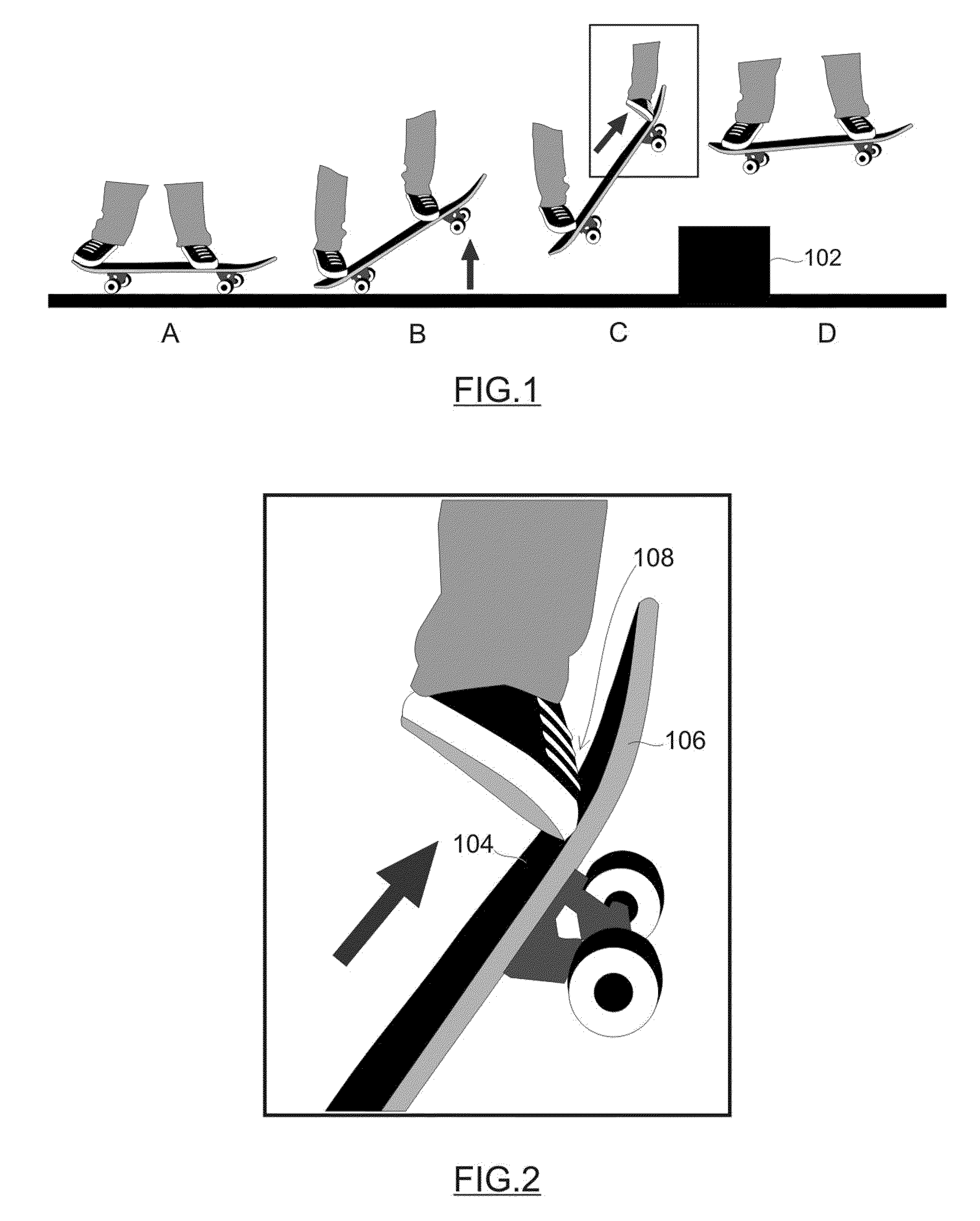
[0004] Most of modern skateboarding tricks are based on a maneuver known as the ollie. This fundamental and basic trick is a no-handed jump during which the skateboard is propelled upward as the skateboarder leaps in the air. FIG. 1 depicts a sequence (from left to right) of a skateboarder performing an ollie over an obstacle 102. The ollie is based on the motion of slapping the tail of the skateboard with the back foot (FIG. 1b), while jumping at the same time. In conjunction with the jump, the skateboarder drags his front foot upward (FIG. 1c) toward the nose of the skateboard deck. This dragging motion allows the skateboarder to pull the skateboard higher, and it causes the skateboard to pivot about the front foot, thus making it appear to "stick" to the skateboarder's back foot (FIG. 1d). The dragging motion also stabilizes the jump and allows the skateboarder to land parallel to the ground.
[0005] As shown in the detailed view of FIG. 2, when the skateboarder drags his foot upward during an ollie, the shoe tends to scrape against the grip tape 104 that is adhered to the top of the skateboard deck 106. In particular, the side and top of the shoe near the toe area (as identified by reference number 108 in FIG. 2) will directly contact and scrape against the grip tape 104 during an ollie. The sandpaper-like surface of the grip tape 104 abrades the shoe, and such abrasion can be very detrimental to the shoe. Indeed, the ollie is the fundamental and basic trick that is performed often by skateboarders, and ollies lead to the quick destruction of skateboarding shoes (e.g., broken laces, tears or holes in the shoe material, etc.). Moreover, the damage caused by ollies is typically more severe on the front shoe because most skateboarders primarily ride with either their left foot forward or their right foot forward. Therefore, the shoe of the back foot is less frequently exposed to grip tape scraping caused by ollies.
BRIEF DESCRIPTION OF THE DRAWINGS
[0006] A more complete understanding of the subject matter may be derived by referring to the detailed description and claims when considered in conjunction with the following figures, wherein like reference numbers refer to similar elements throughout the figures.
[0007] FIG. 1 is a diagram that shows a sequence of a skateboarder performing an ollie;
[0008] FIG. 2 is a detailed diagram that shows how a shoe drags against the skateboard deck during an ollie;
[0009] FIG. 2.1 is a side view of a shoe that has signs of wear and tear caused by ollies;
[0010] FIG. 3 is a front view of a shoe having installed thereon an exemplary embodiment of a shoe protector;
[0011] FIG. 4 is a bottom view of an exemplary embodiment of a shoe protector;
[0012] FIG. 5 is a front edge view of the shoe protector depicted in FIG. 4;
[0013] FIG. 6 is a top view of the shoe protector depicted in FIG. 4;
[0014] FIG. 7 is a side view of the shoe depicted in FIG. 3;
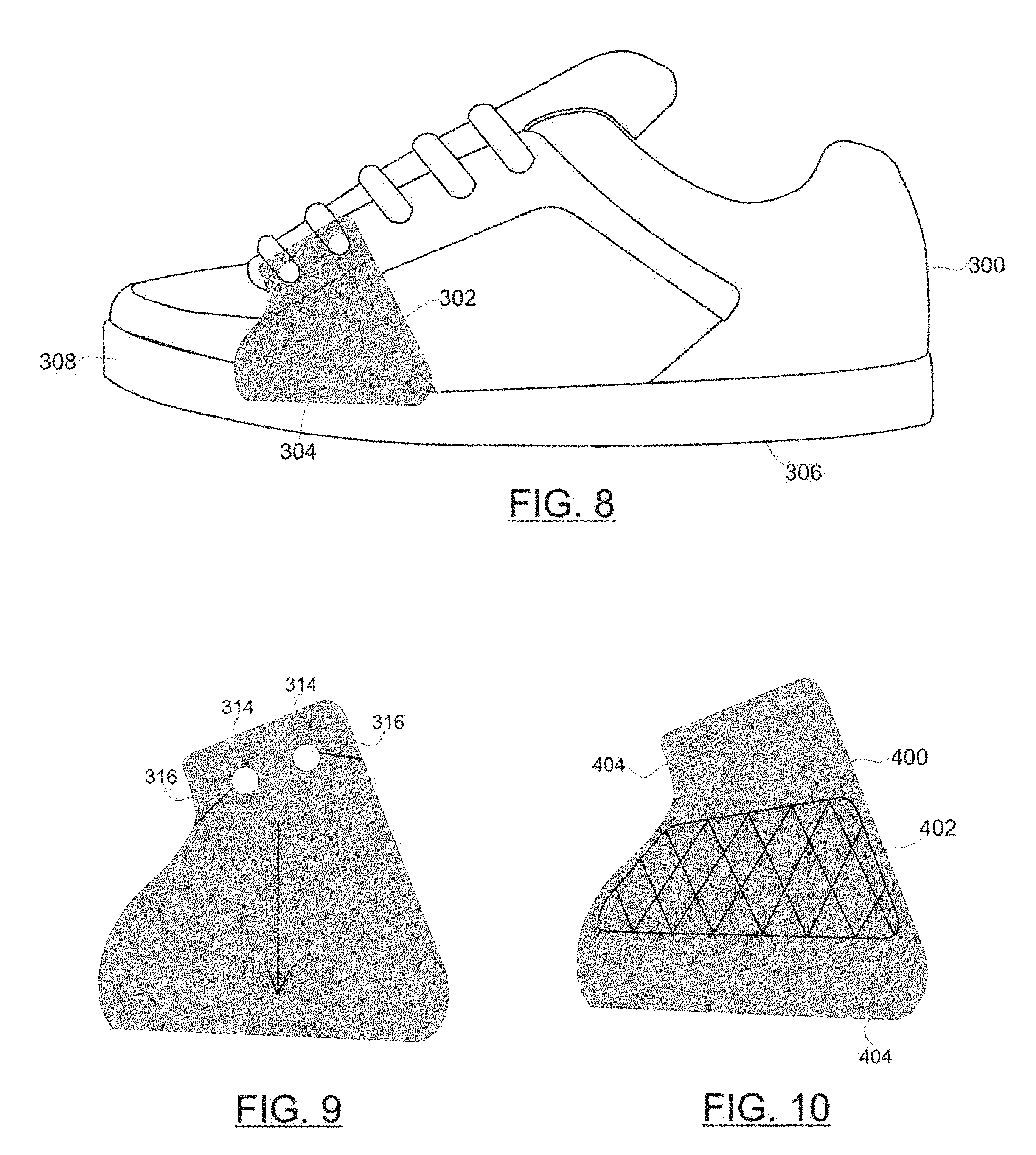
[0015] FIG. 8 is a side view of the shoe 300 and the shoe protector 302 (where a portion of the shoe protector 302 is shown in phantom);
[0016] FIG. 9 is a top view of a shoe protector that uses slits for the shoelace holes; and
[0017] FIGS. 10-12 are top views of shoe protectors that have various surface features.
DETAILED DESCRIPTION
[0018] The following detailed description is merely illustrative in nature and is not intended to limit the embodiments of the subject matter or the application and uses of such embodiments. As used herein, the word "exemplary" means "serving as an example, instance, or illustration." Any implementation described herein as exemplary is not necessarily to be construed as preferred or advantageous over other implementations. Furthermore, there is no intention to be bound by any expressed or implied theory presented in the preceding technical field, background, brief summary or the following detailed description.
[0019] In addition, certain terminology may also be used in the following description for the purpose of reference only, and thus are not intended to be limiting. For example, terms such as "upper", "lower", "above", and "below" refer to directions in the drawings to which reference is made. Terms such as "front", "back", "rear", "side", "outboard," and "inboard" describe the orientation and/or location of portions of the component within a consistent but arbitrary frame of reference which is made clear by reference to the text and the associated drawings describing the component under discussion. Such terminology may include the words specifically mentioned above, derivatives thereof, and words of similar import. Similarly, the terms "first", "second" and other such numerical terms referring to structures do not imply a sequence or order unless clearly indicated by the context.
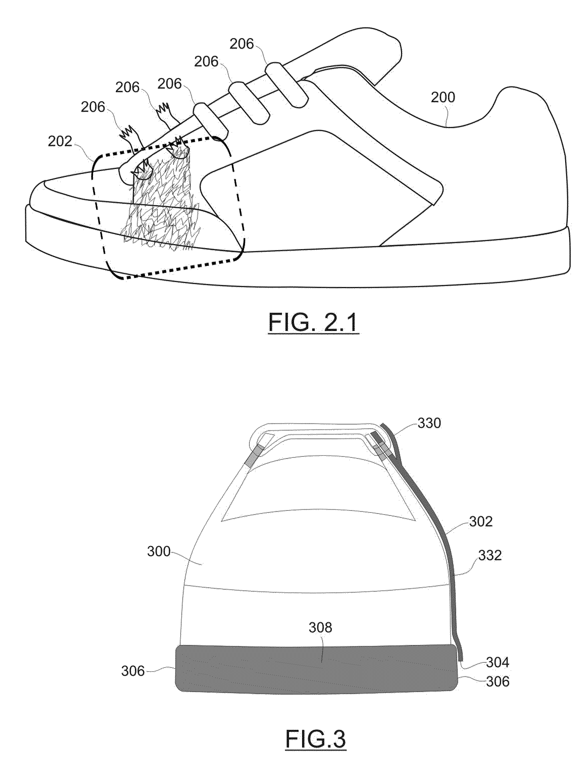
[0020] FIG. 2.1 is a side view of a shoe 200 that has signs of wear and tear caused by ollies. In particular, repeated ollies tend to wear and damage an "ollie area" 202 of the shoe 200. The ollie area 202 is typically located on the outer side of the shoe 200 and closer to the toe than the heel. Usually, the ollie area 202 is near the portion of the shoe that covers the pinkie toe. Moreover, the ollie area 202 often spans a portion at or near the top of the shoe 200. For example, the ollie area 202 might encompass the area near and including the first shoelace hole (relative to the toe end of the shoe 200), the first two shoelace holes, the first three shoelace holes, or the like. Indeed, as depicted in FIG. 2.1, the shoelaces 206 near the toe end of the shoe are often severed after only a few ollies because the shoelaces 206 are usually exposed in the ollie area 202.
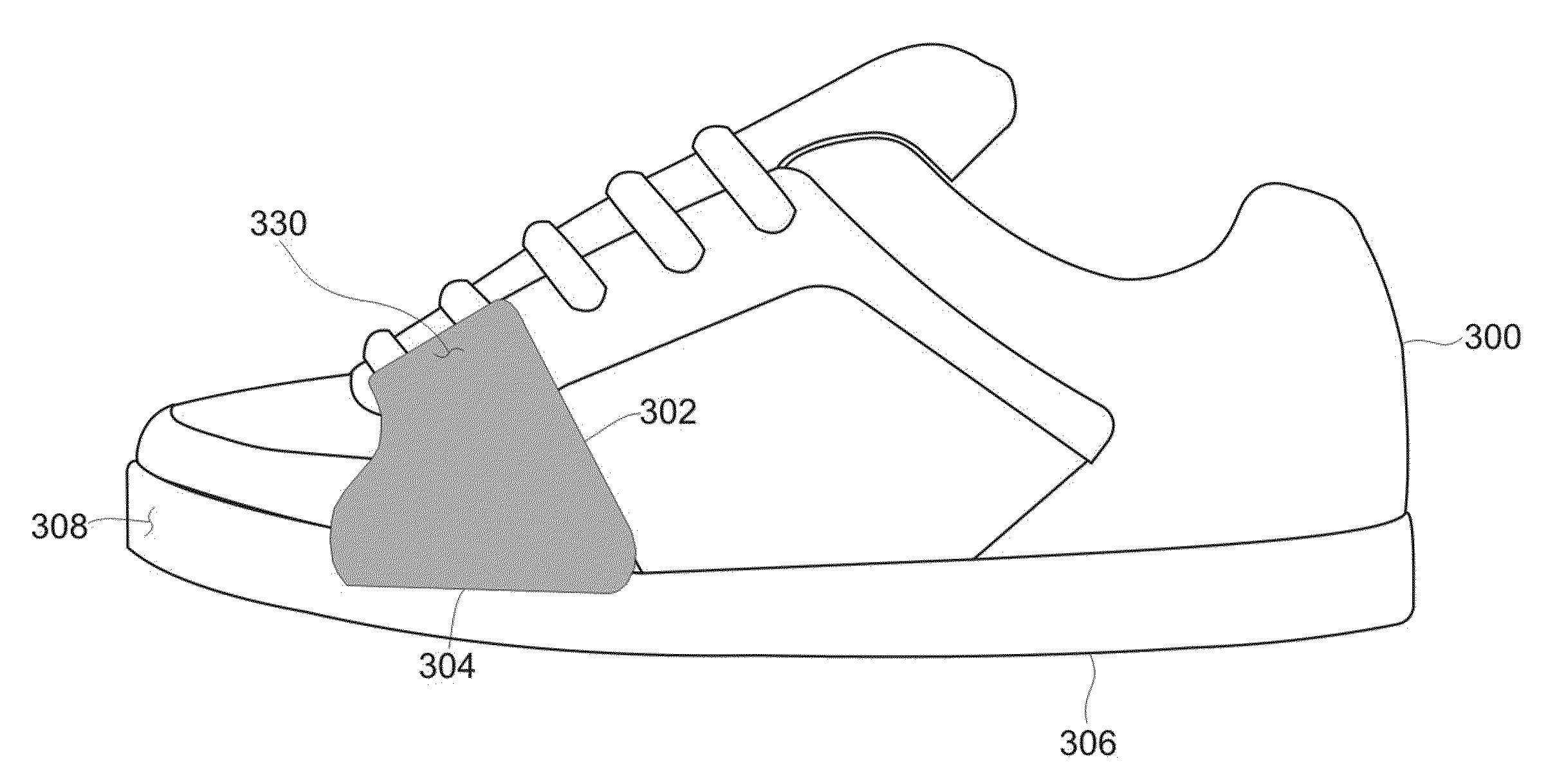
[0021] This description is directed to a simple, elegant, and effective shoe protector that is designed to "shield" the shoe from the wear and tear that is typically associated with ollies. In this regard, FIG. 3 is a front view of a shoe 300 having installed thereon an exemplary embodiment of a shoe protector 302, FIG. 4 is a bottom view of the shoe protector 302, FIG. 5 is a front edge view of the shoe protector 302, FIG. 6 is a top view of the shoe protector 302, FIG. 7 is a side view of the shoe 300 and the shoe protector 302, and FIG. 8 is a side view of the shoe 300 and the shoe protector 302 (where a portion of the shoe protector 302 is shown in phantom).
[0022] When uninstalled, the shoe protector 302 is a generally flat and relatively thin construction of one or more materials, composites, laminates, etc. As shown in FIGS. 4, 6, 7, and 8, the two major surfaces of the shoe protector 302 are shaped and sized such that the shoe protector 302 can provide adequate protection for the ollie area 202 of the shoe 300. Thus, the overall size, shape, perimeter, and configuration of the two major surfaces of the shoe protector 300 could be designed in a universal manner to accommodate a typical shoe that is used by skateboarders. In practice, the shoe protector 300 could be manufactured in different sizes to fit different shoe sizes.
[0023] As shown in FIG. 3, in certain embodiments the lower edge 304 of the shoe protector 302 extends to the sidewall portion 306 of the sole 308, but the lower edge 304 does not protrude from the bottom of the sole 308. Alternatively, the lower edge 304 of the shoe protector 302 could terminate above the sidewall portion 306. The width and contour of the shoe protector 302 are configured to provide adequate protection for the ollie area 202 without unnecessarily obscuring too much of the shoe 300. Thus, the two major surfaces of the shoe protector 302 resemble a ski boot in this particular embodiment.
[0024] The body of the shoe protector 302 is formed from a material that is strong and tough enough to withstand the abrasion caused by repeated ollies. In certain embodiments, the material include or be formed from, without limitation: leather; rubber; vinyl; urethane; silicone; suede; canvas; cloth; synthetic leather; adhesive tape (e.g., electrical tape, duct tape, or the like); a composite material such as KEVLAR; a lamination of different material layers; plastic; or any suitable combination thereof. Regardless of the chosen material, the shoe protector 302 should be tough, resilient, and flexible. The flexibility enables the shoe protector 302 to be installed onto the outer surface of the shoe 300 in a conformal manner that follows the general shape and contour of the shoe 300. In certain embodiments, the shoe protector 302 is formed from a solid piece of material. In one exemplary implementation, the shoe protector 302 is formed from a lamination of multiple layers of adhesive tape (preferably, duct tape, which is often referred to as duck tape or gray tape). The number of layers can be selected to form a relatively thin shoe protector 302 (for example, one to three layers) or a relatively thick shoe protector 302 (for example, three to six layers). Moreover, the lamination could be formed such that the shoe protector 302 has a uniform number of layers or a non-uniform number of layers that results in a varied thickness. For example, the shoe protector 302 could be fabricated with additional layers near its center 310 (see FIG. 6), which typically corresponds to the area exposed to the most abrasion caused by ollies.
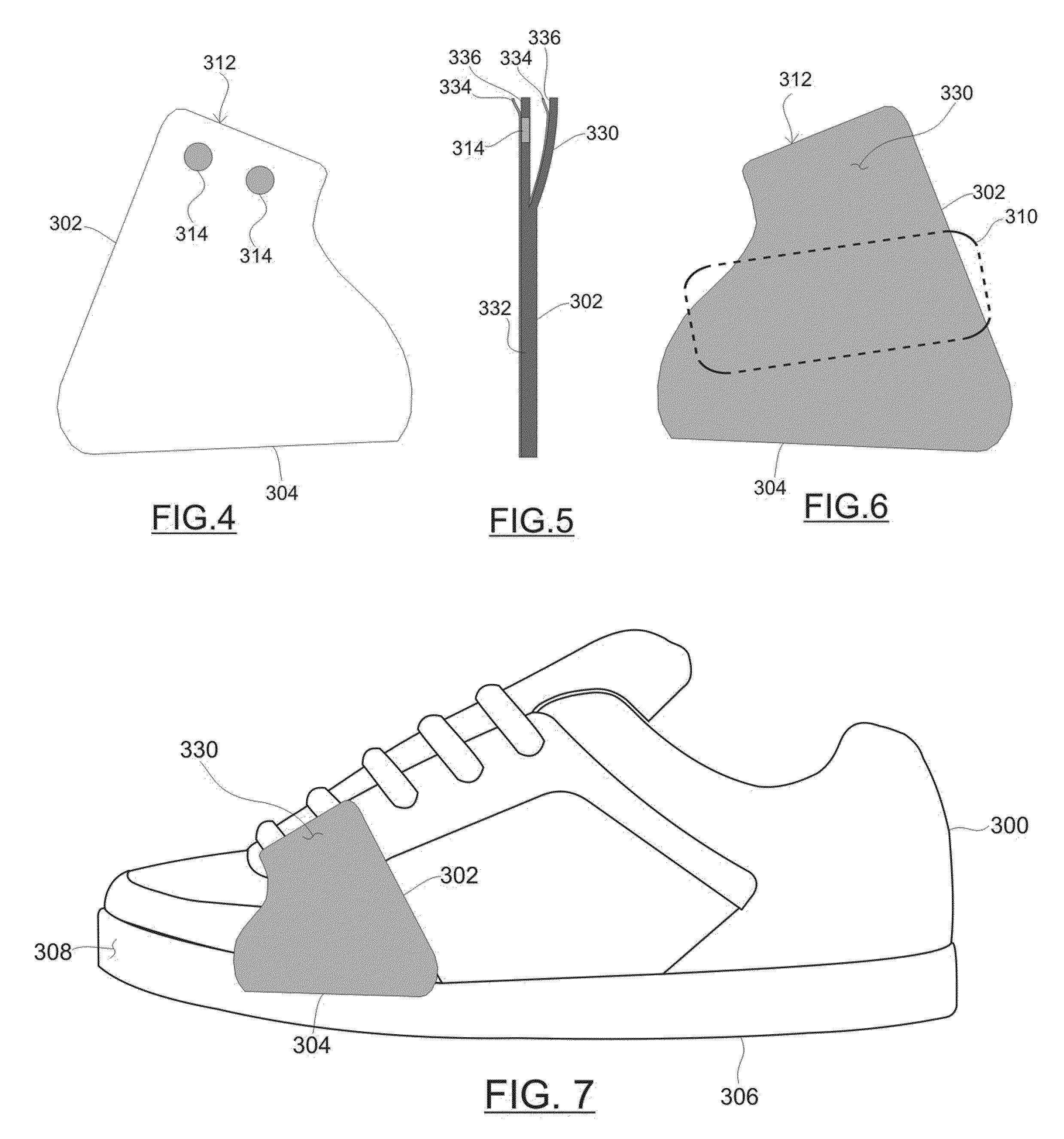
[0025] The upper section of the shoe protector 302 forms a tab 312 that can be used to install the shoe protector 302 onto the shoe 300. The tab 312 includes one or more shoelace holes 314 formed therein (in the illustrated embodiment, two shoelace holes 314). The shoelace holes 314 are sized, shaped, and spaced apart to accommodate the shoelace pattern of the shoe 300. In some embodiments, the shoe protector 302 could be installed by threading the shoelace into the eyelets of the shoe 300 while, at the same time, threading the shoelace into the shoelace holes 314 (see FIG. 3 and FIG. 8). The shoelace holes 314 function to locate the shoe protector 302 in the proper fore-aft position on the shoe 300, and also function to maintain the shoe protector 302 in its installed position. Referring to FIG. 9, in certain embodiments, the tab 312 includes slits 316 that terminate at the shoelace holes 314, and these slits 316 allow the shoe protector 302 to be easily installed onto the shoe 300 without having to remove or replace the shoelace. The slits 316 may be downwardly angled (as shown in FIG. 9) to facilitate a "hooking" engagement onto the shoelaces. This downward angle allows easy installation while retaining structural integrity and strength to withstand the forces associated with the dragging motion of an ollie. The arrow in FIG. 9 represents how the shoe protector 302 tends to be pulled downward during an ollie. Thus, the downward angle of the slits 316 ensures that the shoe protector does not become dislodged during repeated ollies. It should be appreciated that other slit, tab, and shoelace hole configurations could be utilized in an embodiment of the shoe protector 302.
[0026] It should be realized that the shoelace holes 314 are optional, and that the shoe protector 302 can be modified for use with shoes that do not utilize shoelaces (e.g., slip-on shoes, shoes that use Velcro fastening straps, shoes that use buckles, shoes that use snaps, or the like). As described in more detail below, the shoe protector 302 could employ adhesive or other fastening means to accommodate installation onto shoes that do not use shoelaces.
[0027] Certain embodiments of the shoe protector 302 include an outer flap 330. As shown in FIGS. 3 and 5, the outer flap 330 is located such that when installed it covers the shoelace holes 314. In preferred embodiments, the outer flap 330 has the same perimeter and outline as the underlying tab 312--this gives the shoe protector 302 a clean look. The base of the outer flap 330 may span the entire width of the tab 312, as depicted in FIG. 3 and FIG. 5, or the outer flap 330 may instead be realized as a "pocket" formed over the tab 312. The outer flap 330 provides ollie protection for the area of the shoe 300 near the shoelace holes 314, and it provides ollie protection for the shoelace itself. This is desirable because shoelaces can break after only several ollies have been performed if they are left exposed.
[0028] The outer flap 330 may be fabricated as an integral part of the main body of the shoe protector 302. In this regard, the outer flap 330 may be realized using some of the layers of a laminate construction or otherwise as a "continuation" of the lower portion 332 of the shoe protector 302. For example (as depicted in FIG. 5), the lower portion 332 of the shoe protector 302 could be formed from a number (N) of layers, the tab 312 could be formed from some but not all of the layers (e.g., N-M), and the outer flap 330 could be formed from the remaining number of layers (e.g., M). Of course, as explained above, different thicknesses and different numbers of layers could be used for the various sections of the shoe protector 302, and this particular example is not intended to be limiting or restrictive of the scope of the described subject matter.
[0029] In certain embodiments, the bottom major surface of the shoe protector 302 is adhesive, tacky, or sticky. This adhesive nature facilitates installation of the shoe protector 302 onto the shoe 300, and ensures that the shoe protector 302 remains substantially in place and somewhat stationary in use. In preferred implementations, the entire bottom major surface of the shoe protector 302 is adhesive. Moreover, the shoe protector 302 could be manufactured with a liner 334 backing the adhesive surface. Thus, the user can remove the liner 334 before installing the shoe protector 302.
[0030] In addition, the back surface of the outer flap 330 may be adhesive, tacky, or sticky. This adhesive nature enables the outer flap 330 to adhere to the shoelace and/or a portion of the underlying tab 312 (see FIG. 3). The adhesive nature of the outer flap 330 also reinforces the area of the tab 312 surrounding the shoelace holes 314. This reinforcing characteristic is particularly beneficial for embodiments that utilize the slits 316 described with reference to FIG. 9. For such embodiments, the outer flap 330 functions as a seal against the tab 312 and inhibits separation of the slits 316 after installation. In preferred implementations, the entire back surface of the outer flap 330 is adhesive. Moreover, the shoe protector 302 could be manufactured with a liner 336 backing the adhesive surface of the outer flap 330. Thus, the user can remove the liner 336 while installing the shoe protector 302.
[0031] Although the adhesive surfaces described above are optional, practical implementations utilize them to inhibit movement of the shoe protector 302 during skateboarding and, particularly, during ollies. If the shoe protector 302 is made from layers of adhesive tape, then the adhesive surfaces will be present as an inherent part of the tape layers. In other embodiments, the shoe protector 302 could utilize double-backed adhesive tape for purposes of these adhesive surfaces. In yet other embodiments, an adhesive substance such as a glue could be applied to form the adhesive surfaces. In yet other embodiments, a fastening mechanism or material (e.g., Velcro, snaps, buttons, hooks, straps, etc.) could be used to secure the shoe protector 302 onto the shoe. For example, the shoe protector 302 could be sold as a kit having a hook (or loop) installation piece that is designed to be affixed, attached, or otherwise secured to the shoe. In conjunction with this backing piece, the kit can include any number of protection pieces that are outfitted with a cooperating loop (or hook) bottom surface. In such an implementation, a protection piece can be easily installed and removed from the installation piece. Thus, the kit could contain a plurality of protection pieces and one installation piece that use Velcro as an attachment mechanism. Notably, Velcro installation is very suitable for shoes that do not have shoelaces.
[0032] FIG. 7 and FIG. 8 show the shoe protector 302 after installation onto the shoe 300. The outer flap 330 is folded onto the underlying tab 312 (which is hidden from view in FIG. 7, but is shown in phantom in FIG. 8). Accordingly, the underlying eyelets of the shoe 300, a portion of the shoelace, and the shoelace holes 314 are covered and protected by the outer flap 330. As shown in FIG. 8, the shoelace is threaded into the shoelace holes 314 (for this example, the lowermost two eyelets are aligned with the shoelace holes 314), thus establishing the shoe protector 302 in the desired fore-aft position on the shoe 300. Notably, the shoe protector 302 need not be installed using the lowermost two eyelets, and the user could move the shoe protector 302 up and down as desired. This flexibility allows the user to position the shoe protector 302 as needed to accommodate his particular wear pattern on the shoe 300.
[0033] The skateboard industry is well known for its use of graphics and branding. Thus, the shoe protector 302 could be fabricated in different colors, patterns, and/or designs that add some ornamental flavor to the product. Moreover, stickers or graphics could be applied to the exposed outer surface of the shoe protector 302 to add some distinguishing flair to the product. In this regard, the shoe protector 302 can be used as a branding and marketing tool.
[0034] Moreover, the shoe protector 302 may incorporate features, elements, or characteristics that may be functional and/or ornamental in nature. In this regard, FIGS. 10-12 are top views of shoe protectors that have various surface features. FIG. 10 depicts a shoe protector 400 having a distinctive section 402 formed therein. The distinctive section 402 may be integrally formed in outer surface (or in the outermost layer) of the shoe protector 400, or it may be realized as a "window" or cutout in the outer layer of the shoe protector 400. The distinctive section 402 may be implemented using a different material or combination of materials than the surrounding primary section 404 of the shoe protector 400. For example, the primary section 404 might be formed from duct tape and the distinctive section 402 could be formed from rubber. The specific material used for the distinctive section 402 may be selected from the list set forth above. In certain embodiments, the distinctive section 402 is formed from a material or combination of materials having specific physical traits that benefit ollies and other skateboarding tricks. For example, the distinctive section 402 could be formed from a grippy, tacky, or resilient material that is intended to provide additional grip and surface friction when performing ollies. As mentioned above with reference to FIGS. 1 and 2, successful ollies depend upon friction between the shoe and the grip tape of the skateboard deck. Thus, the distinctive section 402 can be configured and formed from suitable material(s) that increase this friction.
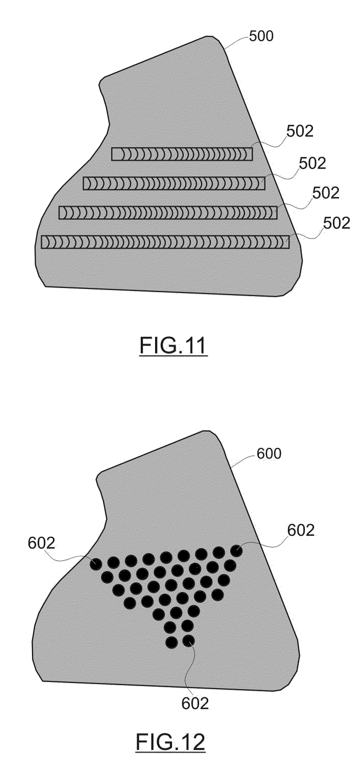
[0035] FIG. 11 depicts another embodiment of a shoe protector 500 that includes surface features designed to improve the quality of ollies. This shoe protector 500 includes protruding bars or ribs 502 on its exposed outer surface. Notably, these ribs 502 are arranged and oriented in a way that anticipates the usual forces associated with an ollie (see the arrow in FIG. 9). In other words, the ribs 502 may be approximately horizontal when the shoe protector 500 is installed, so that they are perpendicular or approximately perpendicular to usual direction of travel of the shoe. This orientation of the ribs 502 results in added grip that can be used to pull the board upward during the ollie. Moreover, the ribs 502 might be formed from a grippy, tacky, or resilient material (such as rubber or urethane) to increase their effectiveness. In practice, the shape, size, pattern, and number of ribs 502 may vary from that shown in FIG. 11.
[0036] FIG. 12 depicts yet another embodiment of a shoe protector 600 that includes surface features designed to improve the quality of ollies. This shoe protector 600 includes protruding bumps 602 on its exposed outer surface. Notably, these bumps 602 could be arranged and oriented in a way that anticipates the usual forces associated with an ollie (see the arrow in FIG. 9). Indeed, the bumps 602 could be arranged in a pattern similar to that shown in FIG. 11. Moreover, the bumps 602 might be formed from a grippy, tacky, or resilient material (such as rubber or urethane) to increase their effectiveness. Furthermore, the bumps 602 could be arranged to form an ornamental or graphical shape (e.g., a star, a skull, a lightning bolt, a logo, etc.). In practice, the shape, size, pattern, and number of bumps 602 may vary from that shown in FIG. 12.
[0037] Although the exemplary embodiments described above relate to a shoe protector intended to protect the "ollie" zone of a shoe, the size, shape, and configuration of the shoe protector can be adjusted and varied as needed to contemplate other areas of a shoe that are susceptible to wear and tear. For instance, a shoe protector could be configured to protect the toe area of the shoe, the heel area of the shoe, or any desired location.
[0038] While at least one exemplary embodiment has been presented in the foregoing detailed description, it should be appreciated that a vast number of variations exist. It should also be appreciated that the exemplary embodiment or embodiments described herein are not intended to limit the scope, applicability, or configuration of the claimed subject matter in any way. Rather, the foregoing detailed description will provide those skilled in the art with a convenient road map for implementing the described embodiment or embodiments. It should be understood that various changes can be made in the function and arrangement of elements without departing from the scope defined by the claims, which includes known equivalents and foreseeable equivalents at the time of filing this patent application.
* * * * *
D00000
D00001
D00002
D00003
D00004
D00005
XML
uspto.report is an independent third-party trademark research tool that is not affiliated, endorsed, or sponsored by the United States Patent and Trademark Office (USPTO) or any other governmental organization. The information provided by uspto.report is based on publicly available data at the time of writing and is intended for informational purposes only.
While we strive to provide accurate and up-to-date information, we do not guarantee the accuracy, completeness, reliability, or suitability of the information displayed on this site. The use of this site is at your own risk. Any reliance you place on such information is therefore strictly at your own risk.
All official trademark data, including owner information, should be verified by visiting the official USPTO website at www.uspto.gov. This site is not intended to replace professional legal advice and should not be used as a substitute for consulting with a legal professional who is knowledgeable about trademark law.