Multi-layer Tubular Conduit
Gardner; Scott
U.S. patent application number 12/784225 was filed with the patent office on 2010-12-30 for multi-layer tubular conduit. This patent application is currently assigned to AD TECHNOLOGIES. Invention is credited to Scott Gardner.
| Application Number | 20100325861 12/784225 |
| Document ID | / |
| Family ID | 43379154 |
| Filed Date | 2010-12-30 |


| United States Patent Application | 20100325861 |
| Kind Code | A1 |
| Gardner; Scott | December 30, 2010 |
MULTI-LAYER TUBULAR CONDUIT
Abstract
Methods and devices related to multi-layer tubular conduit are disclosed. The method of making the multi-layer tubular conduit includes providing a hermetically sealed metal tube, inserting a thermoplastic conduit within the tube, and surrounding the exterior of the tube with an overjacket. The multi-layer tubular conduit device includes three layers: a layer of thermaplastic conduit, a layer of hermetically sealed metal tube, and a layer of overjacket. The three layers are arranged coaxially such that they share a common central axis. The method of use includes installing a multi-layer tubular conduit device in a public or non-public environment. The multi-layer tubular conduit offers mechanical protection from harsh and/or hostile environments while still offering the flexibility of traditional conduit.
| Inventors: | Gardner; Scott; (Knoxville, TN) |
| Correspondence Address: |
    SNR DENTON US LLP
    P.O. BOX 061080
    CHICAGO
    IL
    60606-1080
    US
|
| Assignee: | AD TECHNOLOGIES Knoxville TN |
| Family ID: | 43379154 |
| Appl. No.: | 12/784225 |
| Filed: | May 20, 2010 |
Related U.S. Patent Documents
| Application Number | Filing Date | Patent Number | ||
|---|---|---|---|---|
| 61221307 | Jun 29, 2009 | |||
| Current U.S. Class: | 29/428 ; 138/145; 219/137R; 29/890.14 |
| Current CPC Class: | H02G 3/0468 20130101; F16L 7/00 20130101; F16L 9/147 20130101; F16L 7/02 20130101; H02G 15/00 20130101; Y10T 29/49428 20150115; F16L 57/06 20130101; F16L 59/06 20130101; Y10T 29/49826 20150115; H02G 1/14 20130101 |
| Class at Publication: | 29/428 ; 138/145; 29/890.14; 219/137.R |
| International Class: | B23P 19/04 20060101 B23P019/04; F16L 9/14 20060101 F16L009/14; B23P 11/00 20060101 B23P011/00; B23K 9/02 20060101 B23K009/02 |
Claims
1. A method of making a multi-layer tubular conduit comprising: providing a hermetically sealed metal tube having an inside diameter, an outside diameter, a length, an interior, and an exterior; inserting a thermoplastic conduit coaxially within the hermetically sealed metal tube, the thermoplastic conduit having an inside diameter and an outside diameter less than the inside diameter of the hermetically sealed metal tube; and surrounding the exterior of the hermetically sealed metal tube with an overjacket, the overjacket having an outside diameter and an inside diameter greater than the outside diameter of the hermetically sealed metal tube.
2. The method of claim 1, wherein the hermetically sealed metal tube is stainless steel.
3. The method of claim 1, wherein the hermetically sealed metal tube is corrugated.
4. The method of claim 1, wherein the providing a hermetically sealed metal tube step comprises: providing a plurality of hermetically sealed tubes; and: orbitally welding together the plurality of hermetically sealed tubes end-to-end.
5. The method of claim 1, wherein the thermoplastic conduit is comprised of one of the following: Polyvinylchloride (PVC), Polyethylene (PE), Polyurethane, or Nylon.
6. The method of claim 1, wherein the thermoplastic conduit is a Polyethylene (PE) conduit comprised of one of the following: high-density polyethylene (HDPE), medium density polyethylene (MDPE), or low density polyethylene (LDPE).
7. The method of claim 1, wherein the thermoplastic conduit is a fire retardant material.
8. The method of claim 1, wherein the thermoplastic conduit includes a layer of friction-reducing material.
9. The method of claim 8, wherein the friction-reducing material is a silicone polymer.
10. The method of claim 1, wherein the thermoplastic conduit has an outside diameter in the range of 2 millimeters to 15 inches.
11. The method of claim 1, wherein the thermoplastic conduit is colored with a colored dye.
12. The method of claim 11, wherein the colored thermoplastic conduit includes at least one stripe of contrasting color.
13. The method of claim 2, wherein the stainless steel is type 304 stainless steel.
14. The method of claim 1, wherein the length of the hermetically sealed metal tube is in the range of 80 feet to 6,000 feet.
15. The method of claim 4, wherein the length of the plurality of hermetically sealed metal tubes, orbitally welded together end-to-end, is in the range of 160 feet to 12,000 feet.
16. The method of claim 1, wherein the inside diameter of the hermetically sealed metal tube is in the range of 2 millimeters to 15 inches.
17. The method of claim 1, wherein the outside diameter of the hermetically sealed metal tube is in the range of 2 millimeters to 15 inches.
18. The method of claim 1, wherein the overjacket has a thickness in the range of 0.05 inches to 0.10 inch.
19. The method of claim 1, wherein the overjacket has a thickness in the range of 0.06 inches to 0.08 inches.
20. The method of claim 1, wherein the overjacket has a thickness of 0.070 inches.
21. The method of claim 1, wherein the overjacket is comprised of one of the following: Polyvinylchloride (PVC), Polyethylene (PE), Polyurethane, or Nylon.
22. The method of claim 1, wherein the overjacket is comprised of one of the following: high-density polyethylene (HDPE), medium density polyethylene (MDPE), or low density polyethylene (LDPE).
23. The method of claim 1, wherein the overjacket is a fire retardant material.
24. The method of claim 23, wherein the fire retardant material is Low Smoke Zero Halogen (LSZH), riser rated material, plenum rated material.
25. The method of claim 1, wherein the overjacket is comprised of Polyvinylidene Fluoride (PVDF) or Low Smoke Zero Halogen (LSZH).
26. The method of claim 1, wherein the inside diameter of the overjacket is in the range of 2 millimeters to 15 inches.
27. The method of claim 1, wherein the outside diameter of the overjacket is in the range of 2 millimeters to 15 inches.
28. A multi-layer tubular conduit device comprising: a first layer of thermaplastic conduit having an inside diameter and an outside diameter; a second layer of hermetically sealed metal tube having an inside diameter, an outside diameter, a length, an interior, and an exterior; and a third layer of overjacket having an inside diameter and an outside diameter; wherein: the first layer (i) having an outside diameter less than the inside diameter of the second layer and (ii) having been inserted within the second layer; the third layer (i) having an inside diameter greater than the outside diameter of the second layer and (ii) surrounding the exterior of the second layer; and the first layer, second layer, and third layer are arranged coaxially such that each share a common central axis.
29. A method of using a multi-layer tubular conduit comprising: installing a multi-layer tubular conduit in a public or non-public environment; wherein the multi-layer conduit comprises the multi-layer tubular conduit device of claim 28.
30. A multi-layer tubular conduit as substantially shown and described herein.
Description
CROSS-REFERENCE TO RELATED APPLICATIONS
[0001] This application claims priority pursuant to 35 U.S.C. 119(e) to co-pending U.S. Provisional Patent Application Ser. No. 61/221,307, filed Jun. 29, 2009, the entire disclosure of which is incorporated herein by reference.
FIELD
[0002] The present invention relates generally to tubular conduit with characteristics to improve performance in harsh and/or hostile environments, and more particularly, to a multi-layer tubular conduit and methods related thereto.
BACKGROUND
[0003] Conduit may be used for protecting and positioning cable. Conduit may be installed in a variety of different environments. Sometimes, environmental factors can compromise the integrity of the conduit and affect the cable and/or a corresponding signal. Environmental factors that can compromise the integrity of conduit may include heat, chemicals, humidity, animals, human influence, etc. In some applications, it is desirable to provide a conduit that includes enhanced resistance to certain types of chemicals and gases, in liquid and/or vapor form. Among other shortcomings, current methods and devices for protecting conduit with corrugated steel fail to provide an airtight seal.
[0004] Thus, there exists the need for a conduit with multiple layers to protect the underlying cable from harsh and/or hostile environmental factors.
SUMMARY
[0005] According to an illustrative embodiment, a multi-layer tubular conduit, with special protection for harsh environments, and methods related thereto are disclosed herein.
[0006] One aspect is directed to a method of making a multi-layer tubular conduit. The method includes providing a hermetically sealed metal tube, inserting a thermoplastic conduit within the hermetically sealed metal tube, and surrounding the exterior of the hermetically sealed metal tube with an overjacket.
[0007] Another aspect is directed to a multi-layer tubular conduit. The multi-layer tubular conduit includes a layer of thermaplastic conduit, a layer of hermetically sealed metal tube, and a layer of overjacket. The three layers are arranged coaxially such that they share a common central axis.
[0008] Another aspect is directed to a method of using a multi-layer tubular conduit. The method of use includes installing a multi-layer tubular conduit, as described above, in a public or non-public environment.
[0009] The multi-layer tubular conduit offers mechanical protection from harsh and/or hostile environments while still offering the flexibility of traditional conduit.
[0010] The foregoing and other objects are intended to be illustrative of the invention and are not meant in a limiting sense. Many possible embodiments of the invention may be made and will be readily evident upon a study of the following specification and accompanying drawings comprising a part thereof. Various features and subcombinations of invention may be employed without reference to other features and subcombinations. Other objects and advantages of this invention will become apparent from the following description taken in connection with the accompanying drawings, wherein is set forth by way of illustration and example, an embodiment of this invention and various features thereof.
BRIEF DESCRIPTION OF THE DRAWINGS
[0011] A preferred embodiment of the invention, illustrative of the best mode in which the applicant has contemplated applying the principles, is set forth in the following description and is shown in the drawings and is particularly and distinctly pointed out and set forth in the appended claims.
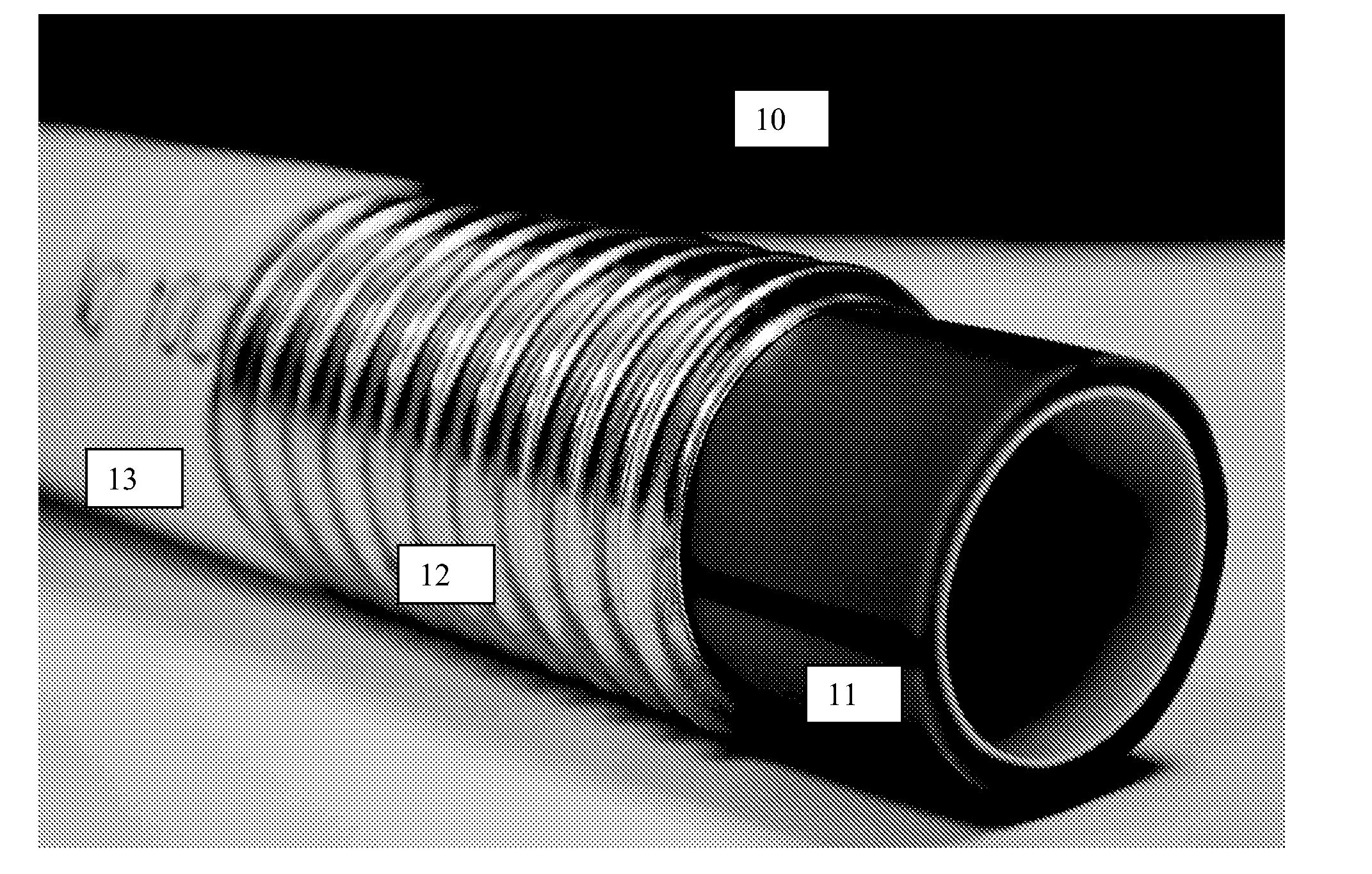
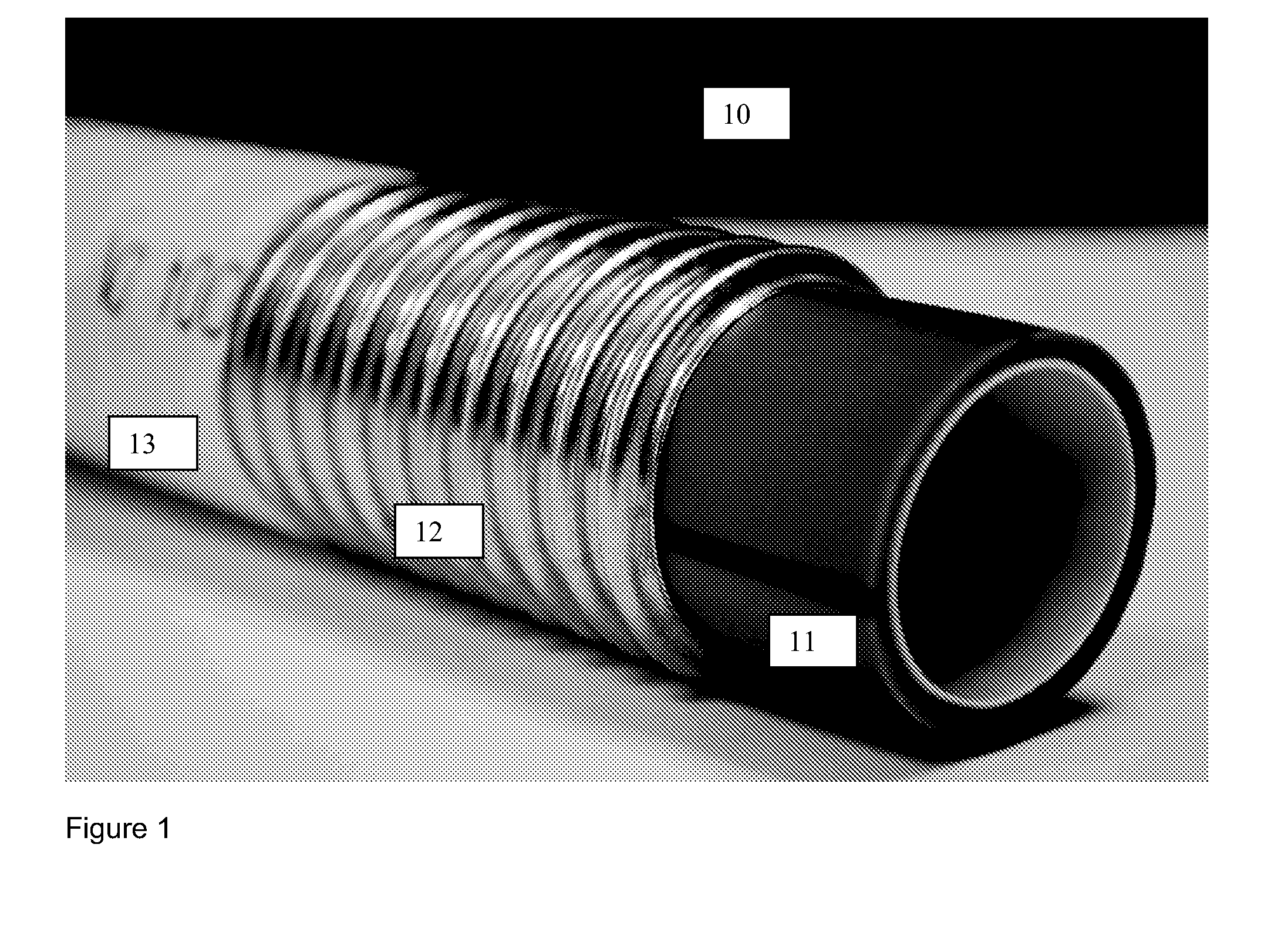
[0012] FIG. 1 is a perspective view of a multi-layer tubular conduit.
[0013] FIG. 2 is another perspective of the multi-layer tubular conduit of FIG. 1.
[0014] FIG. 3 is another perspective of the multi-layer tubular conduit of FIG. 1.
[0015] FIG. 4 is a perspective of an exemplary embodiment of the multi-layer tubular conduit.
[0016] Corresponding reference characters indicate corresponding parts throughout the several views of the drawings.
DETAILED DESCRIPTION
[0017] As required, a detailed description is provided; however, it is to be understood that the disclosed embodiment is merely exemplary of the principles of the invention, which may be embodied in various forms. Therefore, specific structural and functional details disclosed herein are not to be interpreted as limiting, but merely as a basis for the claims and as a representative basis for teaching one skilled in the art to variously employ the present invention in virtually any appropriately detailed structure.
Method of Making
[0018] One aspect is directed to a method of making a multi-layer tubular conduit. The method includes the steps of providing a hermetically sealed metal tube, inserting a thermoplastic conduit within the tube, and surrounding the exterior of the tube with an overjacket.
Providing a Tube
[0019] The step of providing the hermetically sealed metal tube may be accomplished by any known means or by any means to be discovered hereafter. The hermetically sealed metal tube is preferably corrugated and preferably stainless steel. For example, a corrugated, hermetically sealed, stainless steel tube which is available from TITEFLEX CORPORATION--GASTITE DIVISION may be used. In some embodiments, the hermetically sealed metal tube is type 200 series, type 300 series, or type 400 series stainless steel, preferably type 304 (18/8). Other types of stainless steel may be used. In some embodiments, the hermetically sealed metal tube is aluminum, copper, steel or other metal.
[0020] The hermetically sealed metal tube provided may have any length. In some embodiments, the hermetically sealed metal tube has a length in the range of 80 feet to 6000 feet, preferably having a length of 5000 feet. In some embodiments, a plurality of hermetically sealed metal tubes are arranged end-to-end, such that an end of one is aligned with an end of another. The plurality of the tubes are orbitally welded together end-to-end. In this manner, a continuous section of hermetically sealed metal tube is formed having any desired length. Any number of hermetically sealed metal tubes can be orbitally welded together end-to-end in this manner.
[0021] The hermetically sealed metal tube has an inside diameter in the range of 2 millimeters (about 0.8 inches) to 15 inches (about 381 millimeters). The hermetically sealed metal tube has an outside diameter in the range of 2 millimeters (about 0.8 inches) to 15 inches (about 381 millimeters).
Inserting a Conduit Within the Tube
[0022] The step of inserting the thermoplastic conduit within the hermetically sealed metal tube can be accomplished by pushing, pulling or mechanically propelling the thermoplastic conduit into the hermetically sealed metal tube or by wrapping the metal tube around the thermoplastic conduit and welding the metal tube to form a hermetic seal. The thermoplastic conduit is arranged within the hermetically sealed metal tube coaxially such that both share a common central axis. The thermoplastic conduit has an outside diameter that is less than the inside diameter of the corrugated, hermetically sealed tube.
[0023] In some embodiments, the thermoplastic conduit is comprised of any one of the following: Polyvinylchloride (PVC), Polyethylene (PE), Polyurethane, Polyvinylidene Fluoride (PVDF), or Nylon. In some embodiments, the thermoplastic conduit is a Polyethylene (PE) conduit comprised of any one of the following: high-density polyethylene (HDPE), medium density polyethylene (MDPE), low density polyethylene (LDPE), riser-rated material, or plenum rated material. In some embodiments, the thermoplastic conduit is comprised of a fire retardant material, such as riser-rated material, plenum-rated material, or Low Smoke Zero Halogen (LSZH). In some embodiments, the thermoplastic conduit includes a layer of friction-reducing material, such as a silicone polymer.
[0024] In some embodiments, the thermoplastic conduit has an inside diameter in the range of 2 millimeters (about 0.8 inches) to 15 inches (about 381 millimeters). In some embodiments, the thermoplastic conduit has an outside diameter in the range of 2 millimeters (about 0.8 inches) to 15 inches (about 381 millimeters). In some embodiments, the thermoplastic conduit is colored with a colored dye. In some embodiments, the thermoplastic conduit includes at least one stripe of contrasting color.
Surrounding the Exterior of the Tube with an Overjacket
[0025] The step of surrounding the exterior of the tube with an overjacket is accomplished using basic extrusion methods that are otherwise known to those skilled in the art of plastics extrusion. The overjacket has an inside diameter greater than the outside diameter of the hermetically sealed metal tube. In some embodiments, the inside diameter of the overjacket is in the range of 2 millimeters (about 0.08 inches) to 15 inches (about 381 millimeters). In some embodiments, the outside diameter of the overjacket is in the range of 2 millimeters (about 0.08 inches) to 15 inches (about 381 millimeters). In some embodiments, the overjacket has a thickness in the range of 0.05 inches to 0.10 inch, preferably in the range of 0.06 inches to 0.08 inches, more preferably 0.07 inches. In some embodiments, the overjacket is comprised of any one of the following: Polyvinylchloride (PVC), Polyethylene (PE), Polyurethane, or Nylon. In some embodiments, the overjacket is a Polyethylene (PE) overjacket comprised of any one of the following: high-density polyethylene (HDPE), medium density polyethylene (MDPE), or low density polyethylene (LDPE). In some embodiments, the overjacket is comprised of a fire retardant material, such as Low Smoke Zero Halogen (LSZH), riser rated material, or plenum rated material. In some embodiments, the overjacket is comprised of Polyvinylidene Fluoride (PVDF), Low Smoke Zero Halogen (LSZH), riser rated material, plenum rated material, or some other specialty-use material.
Apparatus
[0026] One aspect is directed to a multi-layer tubular conduit apparatus. Referring to FIG. 1, a perspective view of a multi-layer tubular conduit (10) is shown. FIG. 2 shows another perspective view of the multi-layer tubular conduit (10) shown in FIG. 1. FIG. 3 shows another perspective view of the multi-layer tubular conduit (10) shown in FIGS. 1 and 2. The multi-layer tubular conduit (10) shown in the Figures includes at least three layers. From the inside out, the first (innermost) layer includes a thermaplastic conduit (11). The second (middle) layer includes a hermetically sealed metal tube (12). The third (outermost) layer includes an overjacket (13). The first layer, second layer, and third layer are arranged coaxially such that all share a common central axis. FIG. 4 shows a perspective view of another embodiment of the multi-layer tubular conduit (10). FIG. 4 shows a fiber optic cable (14) extended within the interior of the first (innermost) layer.
First Layer
[0027] The first layer includes a thermaplastic conduit (11). The thermoplastic conduit (11) is inserted within the tube (12) coaxially such that they share a common central axis. The thermoplastic conduit (11) has an outside diameter that is less than the inside diameter of the hermetically sealed metal tube (12). In some embodiments, the thermoplastic conduit is comprised of any one of the following: Polyvinylchloride (PVC), Polyethylene (PE), Polyurethane, or Nylon. In some embodiments, the thermoplastic conduit is a Polyethylene (PE) conduit comprised of any one of the following: high-density polyethylene (HDPE), medium density polyethylene (MDPE), or low density polyethylene (LDPE). In some embodiments, the thermoplastic conduit is comprised of a fire retardant material. In some embodiments, the thermoplastic conduit includes a layer of friction-reducing material, such as a silicone polymer.
[0028] In some embodiments, the thermoplastic conduit has an inside diameter in the range of 2 millimeters (about 0.08 inches) to 15 inches (about 381 millimeters). In some embodiments, the thermoplastic conduit has an outside diameter in the range of 2 millimeters (about 0.08 inches) to 15 inches (about 381 millimeters). In some embodiments, the thermoplastic conduit is colored with a colored dye. In some embodiments, the thermoplastic conduit includes at least one stripe of contrasting color.
Second Layer
[0029] The second layer includes a hermetically sealed metal tube (12). The hermetically sealed metal tube (12) may be provided via any known means or by any means to be discovered hereafter. The hermetically sealed metal tube (12) is preferably corrugated and preferably stainless steel. For example, a corrugated, hermetically sealed, stainless steel tube is available from TITEFLEX CORPORATION--GASTITE DIVISION. In some embodiments, the hermetically sealed metal tube (12) is type 200 series, type 300 series, or type 400 series stainless steel, preferably type 304 (18/8). Other types of stainless steel may be used. In some embodiments, the hermetically sealed metal tube (12) is aluminum, copper, steel or other metal.
[0030] The hermetically sealed metal tube (12) may have any length. In some embodiments, the hermetically sealed metal tube (12) has a length in the range of 80 feet to 6000 feet, preferably having a length of 5000 feet. In some embodiments, a plurality of hermetically sealed metal tubes are arranged end-to-end, such that an end of one is aligned with an end of another. The plurality of the tubes are orbitally welded together end-to-end. In this manner, a continuous section of hermetically sealed metal tube is formed having any desired length. Any number of hermetically sealed metal tubes can be orbitally welded together end-to-end in this manner.
[0031] The hermetically sealed metal tube (12) has an inside diameter in the range of 2 millimeters (about 0.08 inches) to 15 inches (about 381 millimeters). The hermetically sealed metal tube (12) has an outside diameter in the range of 2 millimeters (about 0.08 inches) to 15 inches (about 381 millimeters).
Third Layer
[0032] The third layer includes an overjacket (13) surrounding the exterior of the hermetically sealed metal tube (12). The overjacket (13) has an inside diameter greater than the outside diameter of the hermetically sealed metal tube (12). In some embodiments, the inside diameter of the overjacket (13) is in the range of 2 millimeters (about 0.08 inches) to 15 inches (about 381 millimeters). In some embodiments, the outside diameter of the overjacket is in the range of 2 millimeters (about 0.08 inches) to 15 inches (about 381 millimeters). In some embodiments, the overjacket has a thickness in the range of 0.05 inches to 0.10 inch, preferably in the range of 0.06 inches to 0.08 inches, more preferably 0.07 inches. In some embodiments, the overjacket is comprised of any one of the following: Polyvinylchloride (PVC), Polyethylene (PE), Polyurethane, or Nylon. In some embodiments, the overjacket is a Polyethylene (PE) overjacket comprised of any one of the following: high-density polyethylene (HDPE), medium density polyethylene (MDPE), or low density polyethylene (LDPE). In some embodiments, the overjacket is comprised of a fire retardant material. In some embodiments, overjacket is comprised of Polyvinylidene Fluoride (PVDF), Low Smoke Zero Halogen (LSZH), riser rated material, plenum rated material, or some other specialty-use material.
Method of Use
[0033] One aspect is directed to a method of using a multi-layer tubular conduit, such as the multi-layer tubular conduit apparatus described above. The method includes installing a multi-layer tubular conduit apparatus, as described above, in a public or non-public environment.
[0034] The multi-layer tubular conduit may be used to provide a hydrogen resistant environment to reduce attenuation in optical fiber cables. It may be used in military applications to provide protection from jet fuel or other caustic materials. It may be used in security applications to provide additional protection against physical penetration by foreign objects. It may be used in steam tunnel or other high temperature applications. It may be used to protect the conduit (and cable) from woodpeckers, gophers, or other animals. It may be used for protection from sharp objects in the ground, such as rock or metal. It could be used in conjunction with a plenum or riser jacket for additional security and/or protection. The multi-layer tubular conduit may be used with other micro-designs, such as FuturePath MicroDucts, available from Dura-Line Corporation.
[0035] In the foregoing description, certain terms have been used for brevity, clearness and understanding; but no unnecessary limitations are to be implied therefrom beyond the requirements of the prior art, because such terms are used for descriptive purposes and are intended to be broadly construed. Moreover, the description and illustration of the invention is by way of example, and the scope of the invention is not limited to the exact details shown or described.
[0036] Although the foregoing detailed description of the present invention has been described by reference to an exemplary embodiment, and the best mode contemplated for carrying out the present invention has been shown and described, it will be understood that certain changes, modification or variations may be made in embodying the above invention, and in the construction thereof, other than those specifically set forth herein, may be achieved by those skilled in the art without departing from the spirit and scope of the invention, and that such changes, modification or variations are to be considered as being within the overall scope of the present invention. Therefore, it is contemplated to cover the present invention and any and all changes, modifications, variations, or equivalents that fall with in the true spirit and scope of the underlying principles disclosed and claimed herein. Consequently, the scope of the present invention is intended to be limited only by the attached claims, all matter contained in the above description and shown in the accompanying drawings shall be interpreted as illustrative and not in a limiting sense.
[0037] Having now described the features, discoveries and principles of the invention, the manner in which the invention is constructed and used, the characteristics of the construction, and advantageous, new and useful results obtained; the new and useful structures, devices, elements, arrangements, parts and combinations, are set forth in the appended claims.
[0038] It is also to be understood that the following claims are intended to cover all of the generic and specific features of the invention herein described, and all statements of the scope of the invention which, as a matter of language, might be said to fall therebetween.
* * * * *
D00000
D00001
D00002
D00003
D00004
XML
uspto.report is an independent third-party trademark research tool that is not affiliated, endorsed, or sponsored by the United States Patent and Trademark Office (USPTO) or any other governmental organization. The information provided by uspto.report is based on publicly available data at the time of writing and is intended for informational purposes only.
While we strive to provide accurate and up-to-date information, we do not guarantee the accuracy, completeness, reliability, or suitability of the information displayed on this site. The use of this site is at your own risk. Any reliance you place on such information is therefore strictly at your own risk.
All official trademark data, including owner information, should be verified by visiting the official USPTO website at www.uspto.gov. This site is not intended to replace professional legal advice and should not be used as a substitute for consulting with a legal professional who is knowledgeable about trademark law.