Security light
Paredes December 22, 2
U.S. patent number RE48,362 [Application Number D/722,732] was granted by the patent office on 2020-12-22 for security light. This patent grant is currently assigned to HEATHCO LLC. The grantee listed for this patent is HeathCo LLC. Invention is credited to Apollo Paul Paredes.


View All Diagrams
| United States Patent | RE48,362 |
| Paredes | December 22, 2020 |
Security light
| Inventors: | Paredes; Apollo Paul (Livonia, MI) | ||||||||||
|---|---|---|---|---|---|---|---|---|---|---|---|
| Applicant: |
|
||||||||||
| Assignee: | HEATHCO LLC (Bowling Green,
KY) |
||||||||||
| Family ID: | 64500765 | ||||||||||
| Appl. No.: | D/722,732 | ||||||||||
| Filed: | January 31, 2020 |
Related U.S. Patent Documents
| Application Number | Filing Date | Patent Number | Issue Date | ||
|---|---|---|---|---|---|
| Reissue of: | 29601833 | Apr 26, 2017 | D835834 | Dec 11, 2018 | |
| Current U.S. Class: | D26/120 |
| Current CPC Class: | F21S 8/036 (20130101); F21V 23/0471 (20130101); F21V 21/28 (20130101) |
| Current International Class: | F21S 8/04 (20060101); 2699 () |
| Field of Search: | ;D26/24,51,61,63,65,72,80,118,120,128 |
References Cited [Referenced By]
U.S. Patent Documents
| D264253 | May 1982 | Goldschmidt |
| 4380792 | April 1983 | Terrell |
| D269210 | May 1983 | Cutlip |
| D336756 | June 1993 | Meisner |
| 5649761 | July 1997 | Sandell |
| D385370 | October 1997 | Moore |
| D386801 | November 1997 | Orgovan |
| D386802 | November 1997 | Kim |
| 5726706 | March 1998 | Walsh |
| D457540 | May 2002 | Kieronski |
| D477105 | July 2003 | Herst |
| D488105 | April 2004 | Stahel |
| D499823 | December 2004 | Reiss |
| 7168821 | January 2007 | Huang |
| D565786 | April 2008 | Willmorth |
| 7448779 | November 2008 | Coushaine |
| D589640 | March 2009 | Janssen |
| D591444 | April 2009 | Beno |
| D595447 | June 2009 | Purcell |
| D598156 | August 2009 | Xiao |
| D599049 | August 2009 | Guercio |
| 7714243 | May 2010 | Birdwell |
| D621986 | August 2010 | Yan |
| D622886 | August 2010 | Zheng |
| D633646 | March 2011 | Marcaccio |
| D636515 | April 2011 | Wang |
| D641097 | July 2011 | Kocks |
| D642319 | July 2011 | Sprengers |
| D643142 | August 2011 | Kocks |
| D647236 | October 2011 | Chang |
| D649198 | November 2011 | Mims |
| D656267 | March 2012 | Laporte |
| D656502 | March 2012 | Cacioppo |
| D670022 | October 2012 | Green |
| D670023 | October 2012 | Green |
| 8317363 | November 2012 | Zheng |
| D683066 | May 2013 | Myung |
| D688403 | August 2013 | Landefeld |
| D708388 | July 2014 | Lee |
| D720093 | December 2014 | Lee |
| D735927 | August 2015 | Lee |
| D745201 | December 2015 | Lee |
| D757347 | May 2016 | Chen |
| D759291 | June 2016 | Chen |
| D761474 | July 2016 | Chen |
| D764700 | August 2016 | Chen |
| D781481 | March 2017 | Chen |
| D784589 | April 2017 | Chen |
| D788967 | June 2017 | Chen |
| D799104 | October 2017 | Chen |
| D804075 | November 2017 | Fang |
| D820506 | June 2018 | Chen |
| D835834 | December 2018 | Paredes |
| D866057 | November 2019 | Lafleur |
Other References
|
Photograph of product packaging at least as early as Mar. 23, 2017. cited by applicant. |
Primary Examiner: Ly; Darlington
Attorney, Agent or Firm: Middleton Reutlinger
Claims
CLAIM
The ornamental design for a security light, as shown and described.
Description
.[.FIG. 1 is a lower perspective view of a first embodiment of a security light showing the new design;.].
.[.FIG. 2 is a rear perspective view of the security light design of FIG. 1;.].
.[.FIG. 3 is a front view of the security light design of FIG. 1;.].
.[.FIG. 4 is a rear view of the security light design of FIG. 1;.].
.[.FIG. 5 is a left side view of the security light design of FIG. 1;.].
.[.FIG. 6 is a right side view of the security light design of FIG. 1;.].
.[.FIG. 7 is a top view of the security light design of FIG. 1; and,.].
.[.FIG. 8 is a bottom view of the security light design of FIG. 1..].
FIG. .[.1.]. .Iadd.9 .Iaddend.is a .[.lower.]. .Iadd.bottom .Iaddend.perspective view of a security light showing .[.the.]. .Iadd.my .Iaddend.new design;
FIG. .[.2.]. .Iadd.10 .Iaddend.is a rear perspective view .[.of the security light design of FIG. 1.]. .Iadd.thereof.Iaddend.;
FIG. .[.3.]. .Iadd.11 .Iaddend.is a front .Iadd.elevation .Iaddend.view .[.of the security light design of FIG. 1.]. .Iadd.thereof.Iaddend.;
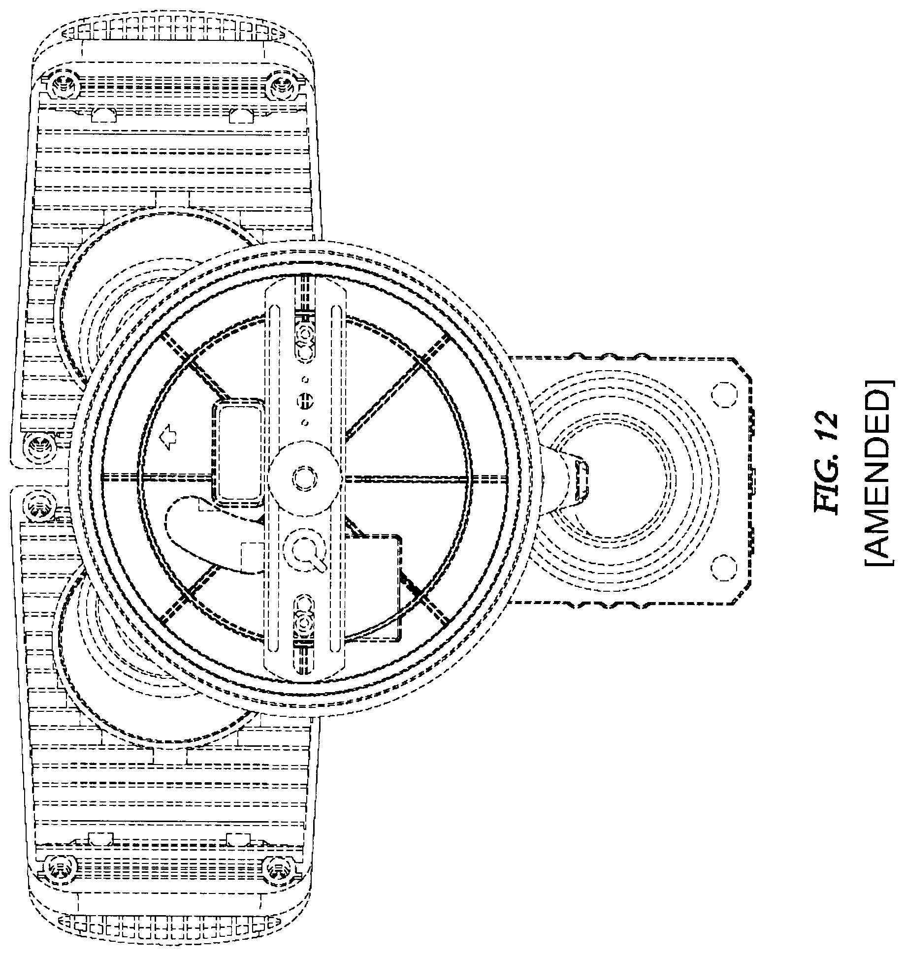
FIG. .[.4.]. .Iadd.12 .Iaddend.is a rear .Iadd.elevation .Iaddend.view .[.of the security light design of FIG. 1.]. .Iadd.thereof.Iaddend.;
FIG. .[.5.]. .Iadd.13 .Iaddend.is a left side .Iadd.elevation .Iaddend.view .[.of the security light design of FIG. 1.]. .Iadd.thereof.Iaddend.;
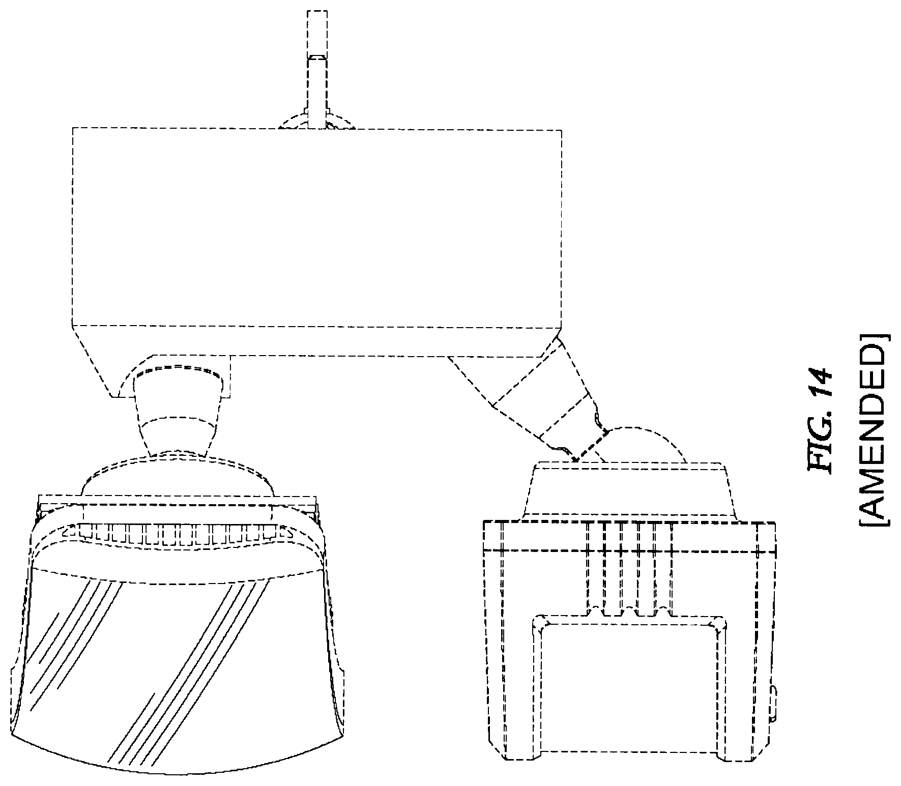
FIG. .[.6.]. .Iadd.14 .Iaddend.is a right side .Iadd.elevation .Iaddend.view .[.of the security light design of FIG. 1.]. .Iadd.thereof.Iaddend.;
FIG. .[.7.]. .Iadd.15 .Iaddend.is a top .Iadd.plan .Iaddend.view .[.of the security light design of FIG. 1.]. .Iadd.thereof; and,.Iaddend.
FIG. .[.8.]. .Iadd.16 .Iaddend.is a bottom .Iadd.plan .Iaddend.view .[.of the security light design of FIG. 1.]. .Iadd.thereof.Iaddend..
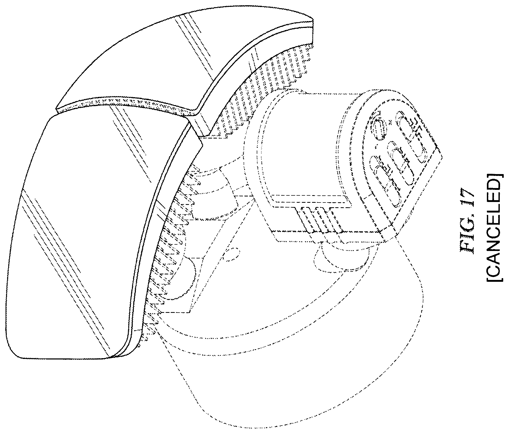
.[.FIG. 17 is a lower perspective view of a third embodiment of a security light showing the new design;.].
.[.FIG. 18 is a rear perspective view of the security light design of FIG. 17;.].
.[.FIG. 19 is a front view of the security light design of FIG. 17;.].
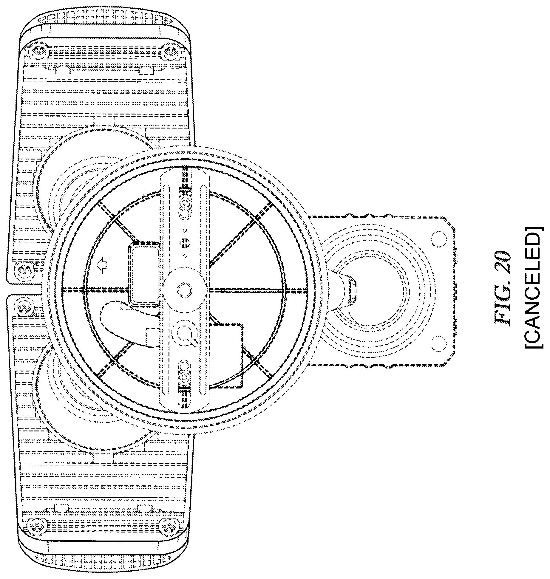
.[.FIG. 20 is a rear view of the security light design of FIG. 17;.].
.[.FIG. 21 is a left side view of the security light design of FIG. 17;.].
.[.FIG. 22 is a right side view of the security light design of FIG. 17;.].
.[.FIG. 23 is a top view of the security light design of FIG. 17; and,.].
.[.FIG. 24 is a bottom view of the security light design of FIG. 17..].
The broken lines represent unclaimed portions of the security light.
* * * * *
D00000
D00001
D00002
D00003
D00004
D00005
D00006
D00007
D00008
D00009
D00010
D00011
D00012
D00013

D00014
D00015

D00016

D00017
D00018

D00019

D00020
D00021

D00022

D00023

D00024

XML
uspto.report is an independent third-party trademark research tool that is not affiliated, endorsed, or sponsored by the United States Patent and Trademark Office (USPTO) or any other governmental organization. The information provided by uspto.report is based on publicly available data at the time of writing and is intended for informational purposes only.
While we strive to provide accurate and up-to-date information, we do not guarantee the accuracy, completeness, reliability, or suitability of the information displayed on this site. The use of this site is at your own risk. Any reliance you place on such information is therefore strictly at your own risk.
All official trademark data, including owner information, should be verified by visiting the official USPTO website at www.uspto.gov. This site is not intended to replace professional legal advice and should not be used as a substitute for consulting with a legal professional who is knowledgeable about trademark law.