Connector device for promoting building skills
McKillip , et al. April 26, 2
U.S. patent number D949,979 [Application Number D/713,541] was granted by the patent office on 2022-04-26 for connector device for promoting building skills. This patent grant is currently assigned to South Dakota Board of Regents. The grantee listed for this patent is South Dakota Board of Regents. Invention is credited to Kay Cutler, Elisabeth Gordon, Tyana Gottsleben, Angela Heinz, Barb Heller, Chris Hume, Todd Letcher, Roxanne Lucchesi, Angela McKillip, Craig Silvernagel, Maggie Smither, Nathan Stang, Abigail Vaz.


| United States Patent | D949,979 |
| McKillip , et al. | April 26, 2022 |
Connector device for promoting building skills
Claims
CLAIM The ornamental design for a connector device for promoting building skills, as shown and described.
| Inventors: | McKillip; Angela (Nunda, SD), Letcher; Todd (Brookings, SD), Lucchesi; Roxanne (Brookings, SD), Silvernagel; Craig (Brookings, SD), Heller; Barb (Brookings, SD), Cutler; Kay (White, SD), Hume; Chris (Broomfield, CO), Vaz; Abigail (Homer, AK), Smither; Maggie (Sioux Falls, SD), Gordon; Elisabeth (Madison, SD), Stang; Nathan (Brookings, SD), Heinz; Angela (Mina, SD), Gottsleben; Tyana (Philip, SD) | ||||||||||
|---|---|---|---|---|---|---|---|---|---|---|---|
| Applicant: |
|
||||||||||
| Assignee: | South Dakota Board of Regents
(Brookings, SD) |
||||||||||
| Appl. No.: | D/713,541 | ||||||||||
| Filed: | November 15, 2019 |
| Current U.S. Class: | D21/488 |
| Current International Class: | 2101 |
| Field of Search: | ;D21/484-505 |
References Cited [Referenced By]
U.S. Patent Documents
| 1678709 | July 1928 | Schurmann |
| 3827177 | August 1974 | Wengel |
| D285463 | September 1986 | Davis |
| D324704 | March 1992 | Lawson |
| 5605486 | February 1997 | Zheng |
| D414276 | September 1999 | Bruno |
| D437423 | February 2001 | Lin |
| D466956 | December 2002 | Manville |
| D468779 | January 2003 | Manville |
| D469825 | February 2003 | Manville |
| 6561866 | May 2003 | Lee |
| 6899588 | May 2005 | Clever |
| D588208 | March 2009 | Sinisi |
| D759765 | June 2016 | Hardstaff |
| D790638 | June 2017 | Kuo |
| D886209 | June 2020 | Grabosch |
| 2003/0129919 | July 2003 | Glickman |
| 2009/0017715 | January 2009 | Grichting |
| 2012/0090356 | April 2012 | Liberman |
| 2016/0346707 | December 2016 | Kuo |
| 2017/0312646 | November 2017 | Chiu |
| 2018/0021689 | January 2018 | Cochella |
| 2018/0345162 | December 2018 | Radics |
| 2020/0254357 | August 2020 | Hart |
| 2020/0330893 | October 2020 | Jensen |
Attorney, Agent or Firm: Suiter Swantz pc llo
Description
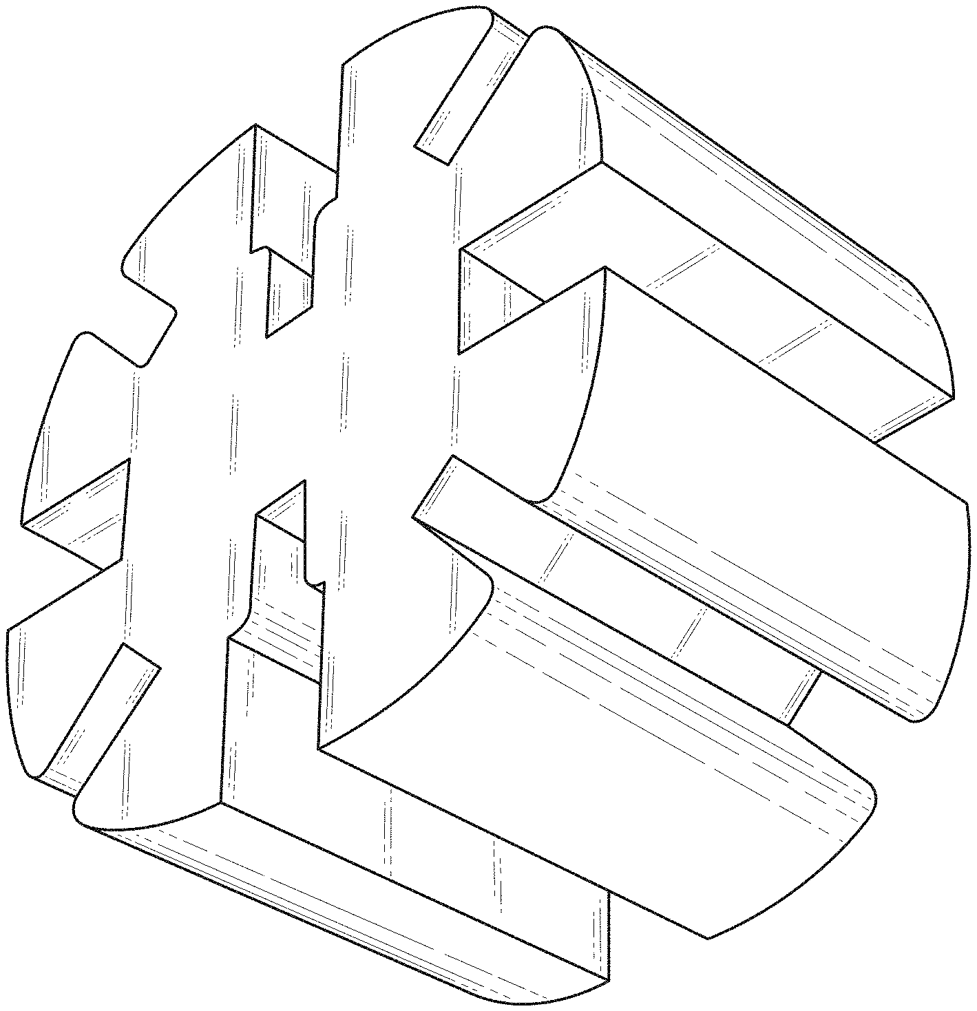
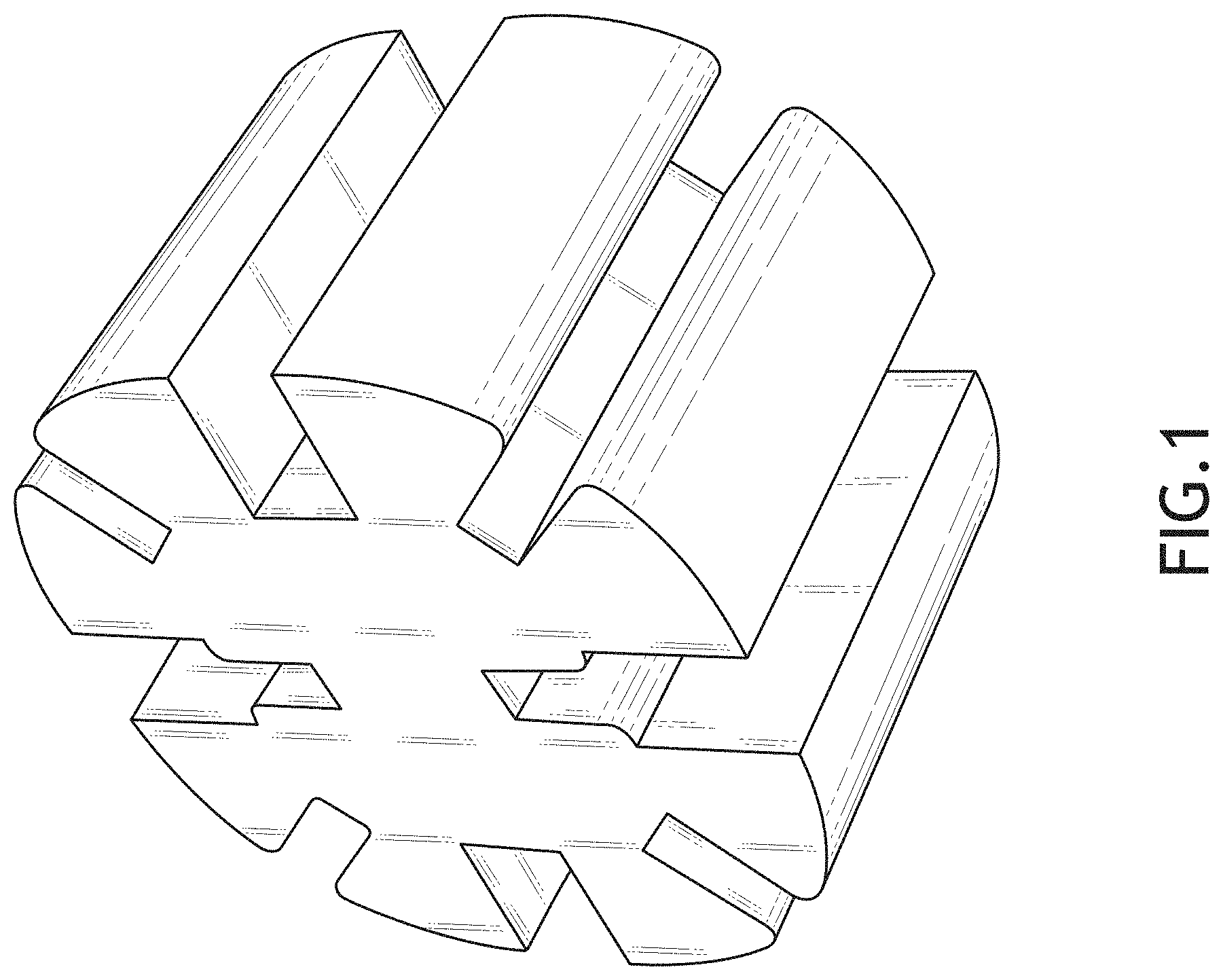
FIG. 1 is a bottom front perspective view of the connector device for promoting building skills;
FIG. 2 is a top view thereof, wherein the bottom view is a mirror image of the top view;
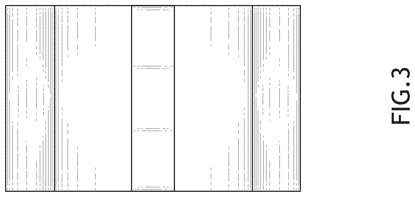
FIG. 3 is a side elevational view thereof, wherein the left-side elevational view is a mirror image of the right-side elevational view;
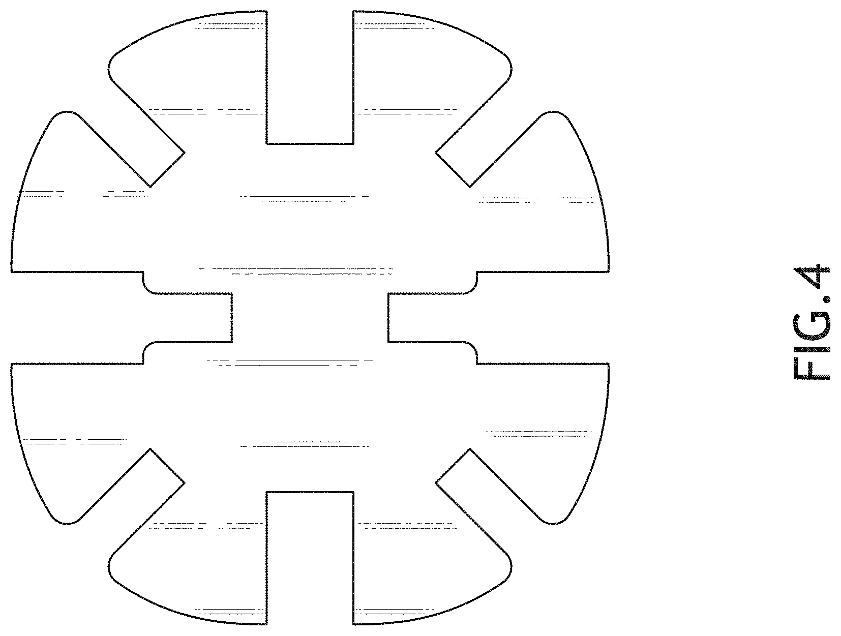
FIG. 4 is a front elevational view, wherein the back elevational view is a mirror image of the front elevational view;
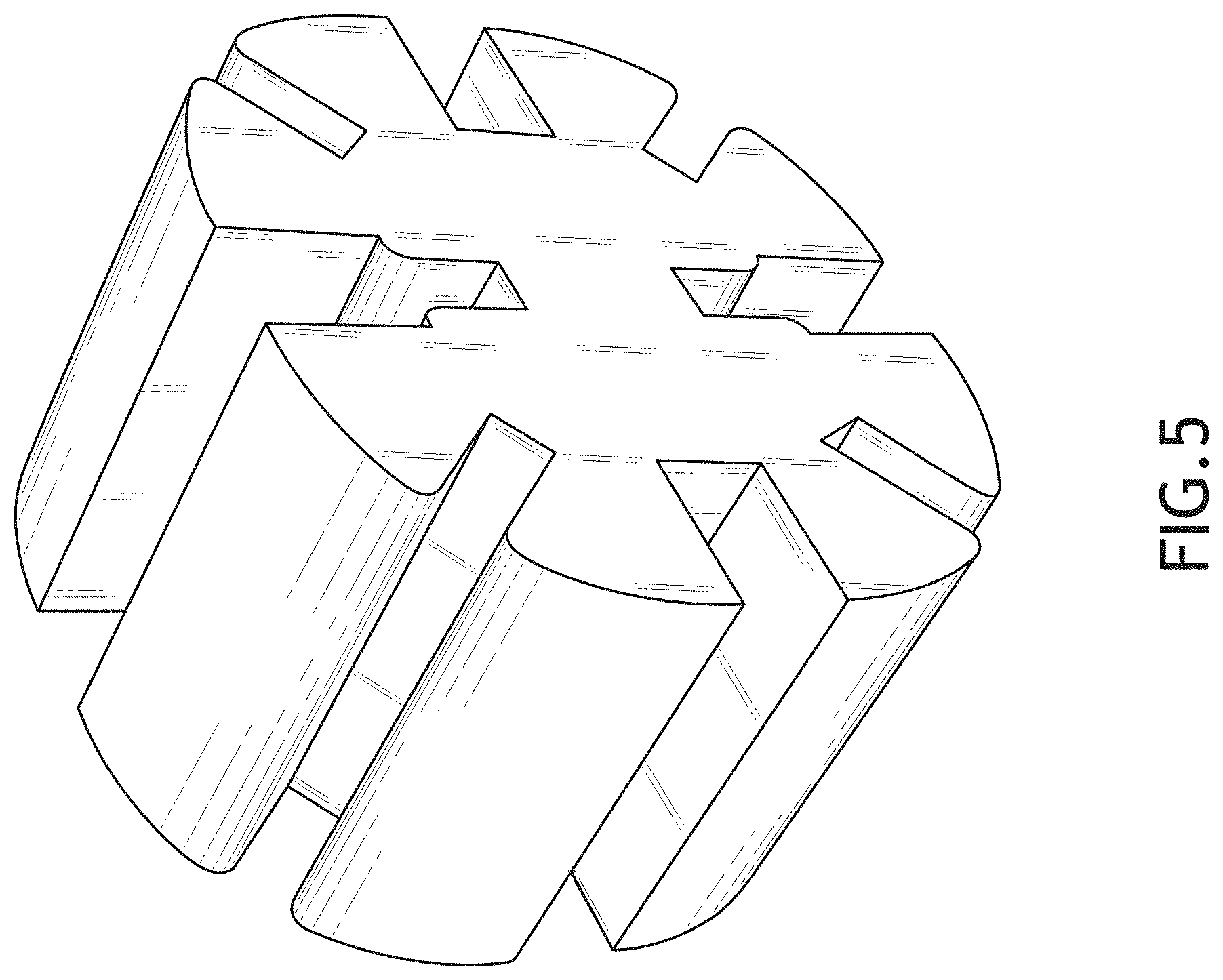
FIG. 5 is a top back perspective view thereof;
FIG. 6 is a reduced environmental view of a connector device forming a joint between a first building piece, a second building piece, and a third building piece;
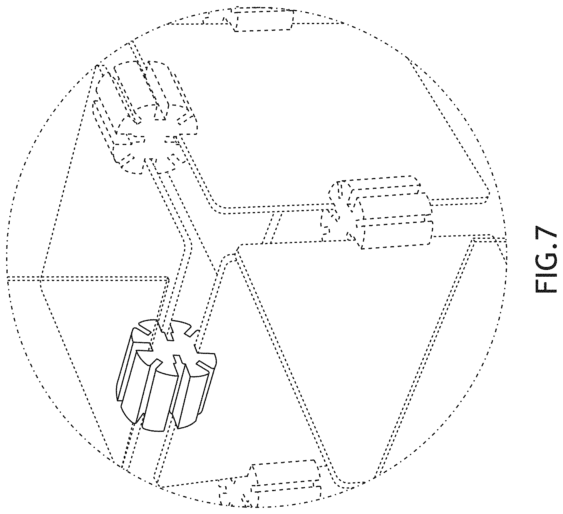
FIG. 7 is a reduced environmental view of multiple connector devices forming joints between multiple building pieces;
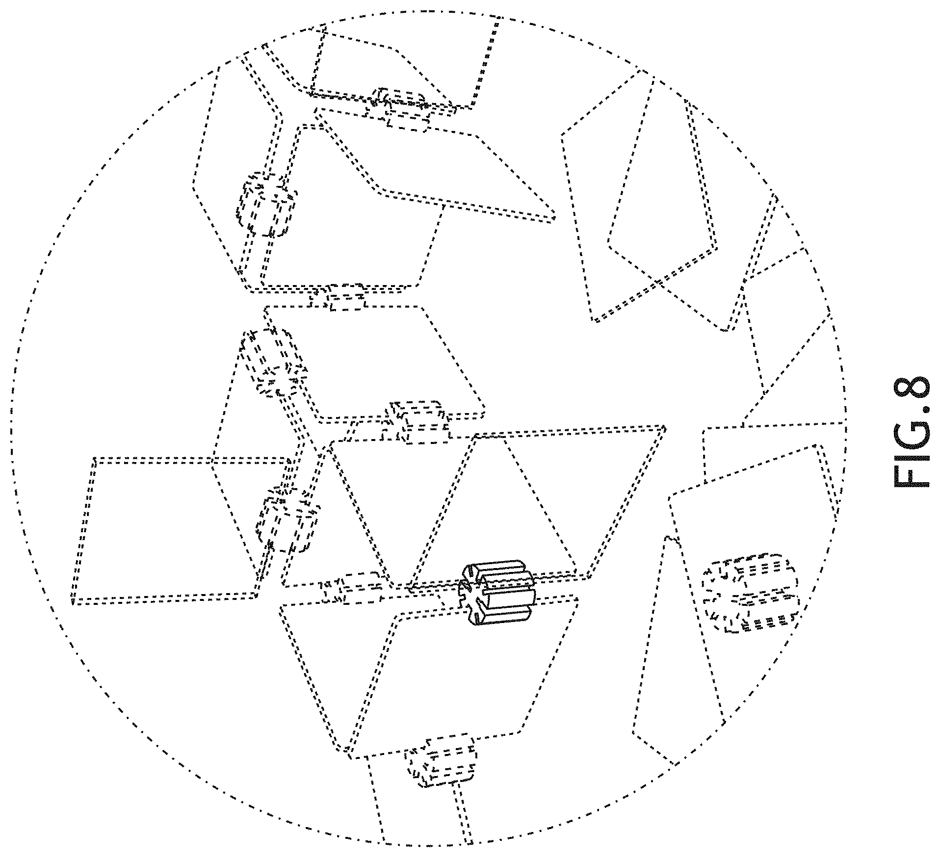
FIG. 8 is a reduced environmental view of multiple connector devices forming joints between multiple building pieces to form a larger building structure; and,
FIG. 9 is a reduced environmental view of multiple connector devices forming joints between multiple building pieces to form a larger building structure.
The dash-dot broken lines represent the boundaries of the enlarged partial views of FIGS. 6-9 and all other broken lines represent portions of the article that form no part of the claimed design. None of the broken lines form a part of the claim.
* * * * *
D00000
D00001
D00002
D00003
D00004
D00005
D00006
D00007
D00008
D00009
XML
uspto.report is an independent third-party trademark research tool that is not affiliated, endorsed, or sponsored by the United States Patent and Trademark Office (USPTO) or any other governmental organization. The information provided by uspto.report is based on publicly available data at the time of writing and is intended for informational purposes only.
While we strive to provide accurate and up-to-date information, we do not guarantee the accuracy, completeness, reliability, or suitability of the information displayed on this site. The use of this site is at your own risk. Any reliance you place on such information is therefore strictly at your own risk.
All official trademark data, including owner information, should be verified by visiting the official USPTO website at www.uspto.gov. This site is not intended to replace professional legal advice and should not be used as a substitute for consulting with a legal professional who is knowledgeable about trademark law.