Injector
Yacoub , et al. April 26, 2
U.S. patent number D949,923 [Application Number D/788,888] was granted by the patent office on 2022-04-26 for injector. This patent grant is currently assigned to Caterpillar Inc.. The grantee listed for this patent is CATERPILLAR INC.. Invention is credited to Cory A. Brown, Hoisan Kim, Satya Naga Deepak Pillarisetti, Kevin J. Schreader, Victor Iskander Yacoub, Jianhua Zhang.


| United States Patent | D949,923 |
| Yacoub , et al. | April 26, 2022 |
Injector
Claims
CLAIM The ornamental design for an injector, as shown and described.
| Inventors: | Yacoub; Victor Iskander (Washington, IL), Brown; Cory A. (Peoria, IL), Pillarisetti; Satya Naga Deepak (Pontiac, IL), Schreader; Kevin J. (East Peoria, IL), Kim; Hoisan (Dunlap, IL), Zhang; Jianhua (Dunlap, IL) | ||||||||||
|---|---|---|---|---|---|---|---|---|---|---|---|
| Applicant: |
|
||||||||||
| Assignee: | Caterpillar Inc. (Peoria,
IL) |
||||||||||
| Appl. No.: | D/788,888 | ||||||||||
| Filed: | August 10, 2021 |
Related U.S. Patent Documents
| Application Number | Filing Date | Patent Number | Issue Date | ||
|---|---|---|---|---|---|
| 29722356 | Jan 29, 2020 | ||||
| Current U.S. Class: | D15/5 |
| Current International Class: | 1501 |
| Field of Search: | ;D15/4,5,6 |
References Cited [Referenced By]
U.S. Patent Documents
| 2621077 | December 1952 | Pieroni |
| 3387790 | June 1968 | De Luca |
| D262969 | February 1982 | Howes |
| D263711 | April 1982 | Dean |
| 4420973 | December 1983 | Garcia |
| 4548356 | October 1985 | Hofmann et al. |
| 4550875 | November 1985 | Teerman et al. |
| 5407131 | April 1995 | Maley |
| 5467924 | November 1995 | Buescher et al. |
| 5628293 | May 1997 | Gibson |
| 5651501 | July 1997 | Maley |
| 5807483 | September 1998 | Cassidy et al. |
| 5927614 | July 1999 | Touvelle et al. |
| 5934559 | August 1999 | Coldren et al. |
| D495341 | August 2004 | O'Brien |
| 7448362 | November 2008 | Seelbach |
| 8333336 | December 2012 | Lewis et al. |
| 10371110 | August 2019 | Brown et al. |
| 2003/0116140 | June 2003 | Forck et al. |
| 2003/0127532 | July 2003 | Coldren et al. |
| 2004/0056114 | March 2004 | Peterson, Jr. |
| 2008/0217421 | September 2008 | Lewis et al. |
| 2010/0170476 | July 2010 | Ganser et al. |
| 2015/0047611 | February 2015 | Yasukawa et al. |
| 2016/0115924 | April 2016 | Meek et al. |
| 2017/0009724 | January 2017 | Izzo et al. |
| 2017/0306913 | October 2017 | Krejci |
| 2018/0023438 | January 2018 | McFarland |
| 2018/0209390 | July 2018 | Caceres |
| 2019/0039178 | February 2019 | Shirai et al. |
| 2019/0040790 | February 2019 | Kusakabe et al. |
| 2019/0063392 | February 2019 | Ishii et al. |
| 2019/0072025 | March 2019 | Rabhi |
| 2019/0162147 | May 2019 | Caceres et al. |
| 2019/0195181 | June 2019 | Brown et al. |
| 2019/0309719 | October 2019 | Brown |
| 2019/0360445 | November 2019 | Sugii |
| 2020/0132030 | April 2020 | Caceres et al. |
| 2020/0173408 | June 2020 | Kim et al. |
| 2020/0240380 | July 2020 | Itaya et al. |
| 206092256 | Apr 2017 | CN | |||
| S59-119059 | Jul 1984 | JP | |||
| H02-140455 | May 1990 | JP | |||
Other References
|
Design U.S. Appl. No. 29/722,349 of Victor Iskander Yacoub et al., entitled "Injector," filed Jan. 29, 2020. cited by applicant . U.S. Design Patent Application of Victor Iskander Yacoub et al., entitled "Injector," filed Aug. 12, 2021. cited by applicant . Design U.S. Appl. No. 29/722,356 of Victor Iskander Yacoub et al., entitled "Injector," filed Jan. 29, 2020. cited by applicant. |
Primary Examiner: Aman; Ania
Attorney, Agent or Firm: Finnegan, Henderson, Farabow, Garrett & Dunner LLP.
Description
FIG. 1 is a front, top, left perspective view of an injector showing the new design;
FIG. 2 is a rear, bottom, right perspective view thereof;
FIG. 3 is front elevation view thereof;
FIG. 4 is a rear elevation view thereof;
FIG. 5 is a right-side elevation view thereof;
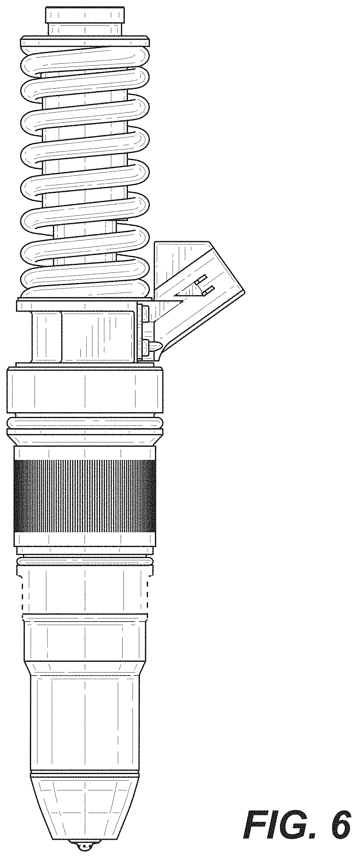
FIG. 6 is a left-side elevation view thereof;
FIG. 7 is a top plan view thereof;
FIG. 8 is a bottom plan view thereof;
FIG. 9 is an enlarged partial front elevation view as indicated in FIG. 3; and,
FIG. 10 is an enlarged partial front elevation view as indicated in FIG. 3.
The broken lines of even length shown in the drawings illustrate portions of the injector that form no part of the claimed design.
* * * * *
D00000
D00001
D00002
D00003
D00004
D00005
D00006
D00007
D00008
D00009
XML
uspto.report is an independent third-party trademark research tool that is not affiliated, endorsed, or sponsored by the United States Patent and Trademark Office (USPTO) or any other governmental organization. The information provided by uspto.report is based on publicly available data at the time of writing and is intended for informational purposes only.
While we strive to provide accurate and up-to-date information, we do not guarantee the accuracy, completeness, reliability, or suitability of the information displayed on this site. The use of this site is at your own risk. Any reliance you place on such information is therefore strictly at your own risk.
All official trademark data, including owner information, should be verified by visiting the official USPTO website at www.uspto.gov. This site is not intended to replace professional legal advice and should not be used as a substitute for consulting with a legal professional who is knowledgeable about trademark law.