Ribbon measuring tool
Franklin , et al. April 26, 2
U.S. patent number D949,721 [Application Number D/730,677] was granted by the patent office on 2022-04-26 for ribbon measuring tool. This patent grant is currently assigned to Unique In The Creek Limited. The grantee listed for this patent is Unique In The Creek Limited. Invention is credited to David Franklin, Laurie MacNeill.


| United States Patent | D949,721 |
| Franklin , et al. | April 26, 2022 |
Ribbon measuring tool
Claims
CLAIM The ornamental design for a ribbon measuring tool, as shown and described.
| Inventors: | Franklin; David (Stony Creek, CA), MacNeill; Laurie (Stony Creek, CA) | ||||||||||
|---|---|---|---|---|---|---|---|---|---|---|---|
| Applicant: |
|
||||||||||
| Assignee: | Unique In The Creek Limited
(Stony Creek, CA) |
||||||||||
| Appl. No.: | D/730,677 | ||||||||||
| Filed: | April 7, 2020 |
| Current U.S. Class: | D10/71; D10/70; D10/65 |
| Current International Class: | 1004 |
| Field of Search: | ;D10/65,71,73,74,70,72,62,64 ;D24/143,140 |
References Cited [Referenced By]
U.S. Patent Documents
| 144003 | October 1873 | Waterbury |
| 224401 | February 1880 | Derickson |
| 575671 | January 1897 | Watts |
| 1522280 | January 1925 | Strom |
| D160541 | October 1950 | Rippon |
| 2826816 | March 1958 | Major |
| D188806 | September 1960 | Le Roy Davis |
| 3197875 | August 1965 | D Azzo |
| 3591904 | July 1971 | Rosene |
| 3816888 | June 1974 | Rather, Jr. |
| D232859 | September 1974 | Colquitt, Jr. |
| 3838519 | October 1974 | Chick |
| 3854179 | December 1974 | Montoya |
| 3857143 | December 1974 | Montory et al. |
| 4337578 | July 1982 | Seals |
| D269504 | June 1983 | Swenson |
| 4930221 | June 1990 | Taylor |
| 4941267 | July 1990 | Miller, Jr. |
| D342030 | December 1993 | Krantz |
| 5582360 | December 1996 | Herman |
| 5617979 | April 1997 | Cavender |
| D380400 | July 1997 | Peard |
| D400810 | November 1998 | Landauer |
| 6000586 | December 1999 | Cavender |
| 6112957 | September 2000 | Massullo |
| D497816 | November 2004 | Sipos |
| 7467471 | December 2008 | Sutter |
| D639684 | June 2011 | Essel |
| 7971367 | July 2011 | Stengel et al. |
| 8403145 | March 2013 | Yip et al. |
| D699132 | February 2014 | Haykeen |
| 8640352 | February 2014 | Porreca et al. |
| D726036 | April 2015 | Zieman |
| 9494405 | November 2016 | Daley et al. |
| 9494406 | November 2016 | Daley et al. |
| D893326 | August 2020 | Tang |
| 2009/0085268 | April 2009 | Ozeki |
| 2014/0190024 | July 2014 | Zhang |
Other References
|
UITC Reindeer Wreath, Featuring Measure Buddy Bows, Easy DIY Christmas Craft, LIVE Replay, Youtube, publication date Nov. 18, 2020, (online) URL: https://www.youtube.com/watch?v=6qF8xvkkWvc (Year: 2020). cited by examiner. |
Primary Examiner: Grabenstetter; L. A.
Assistant Examiner: Suiter; Antoinette Martine
Attorney, Agent or Firm: Woodard, Emhardt, Henry, Reeves & Wagner, LLP
Description
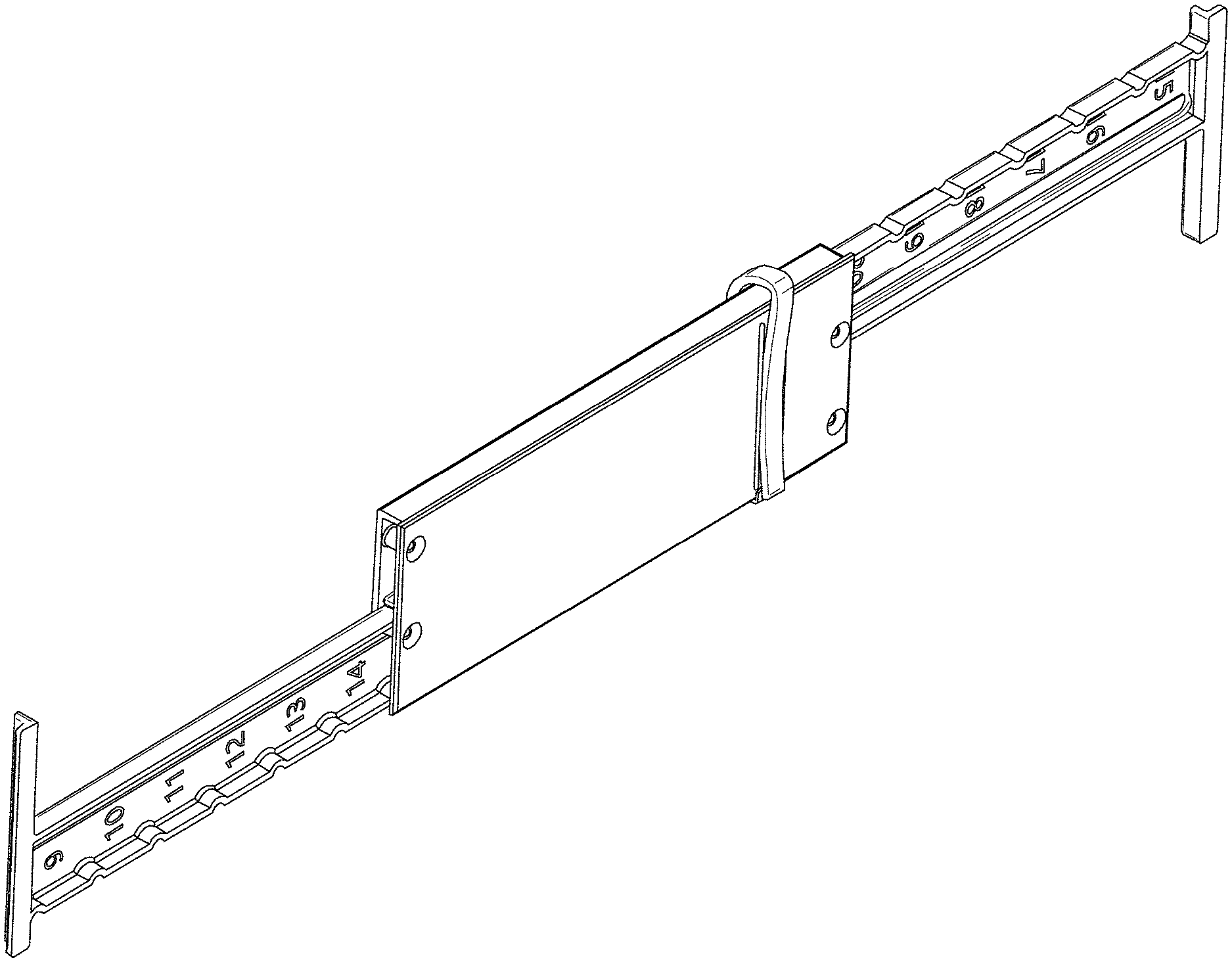
FIG. 1 is a perspective view of the ribbon measuring tool in an extended configuration.
FIG. 2 is a top view of the ribbon measuring tool of FIG. 1.
FIG. 3 is a bottom view of the ribbon measuring tool of FIG. 1.
FIG. 4 is a side view of the ribbon measuring tool of FIG. 1, the opposite side is a mirror image.
FIG. 5 is an end view of the ribbon measuring tool of FIG. 1, the opposite end is a mirror image.
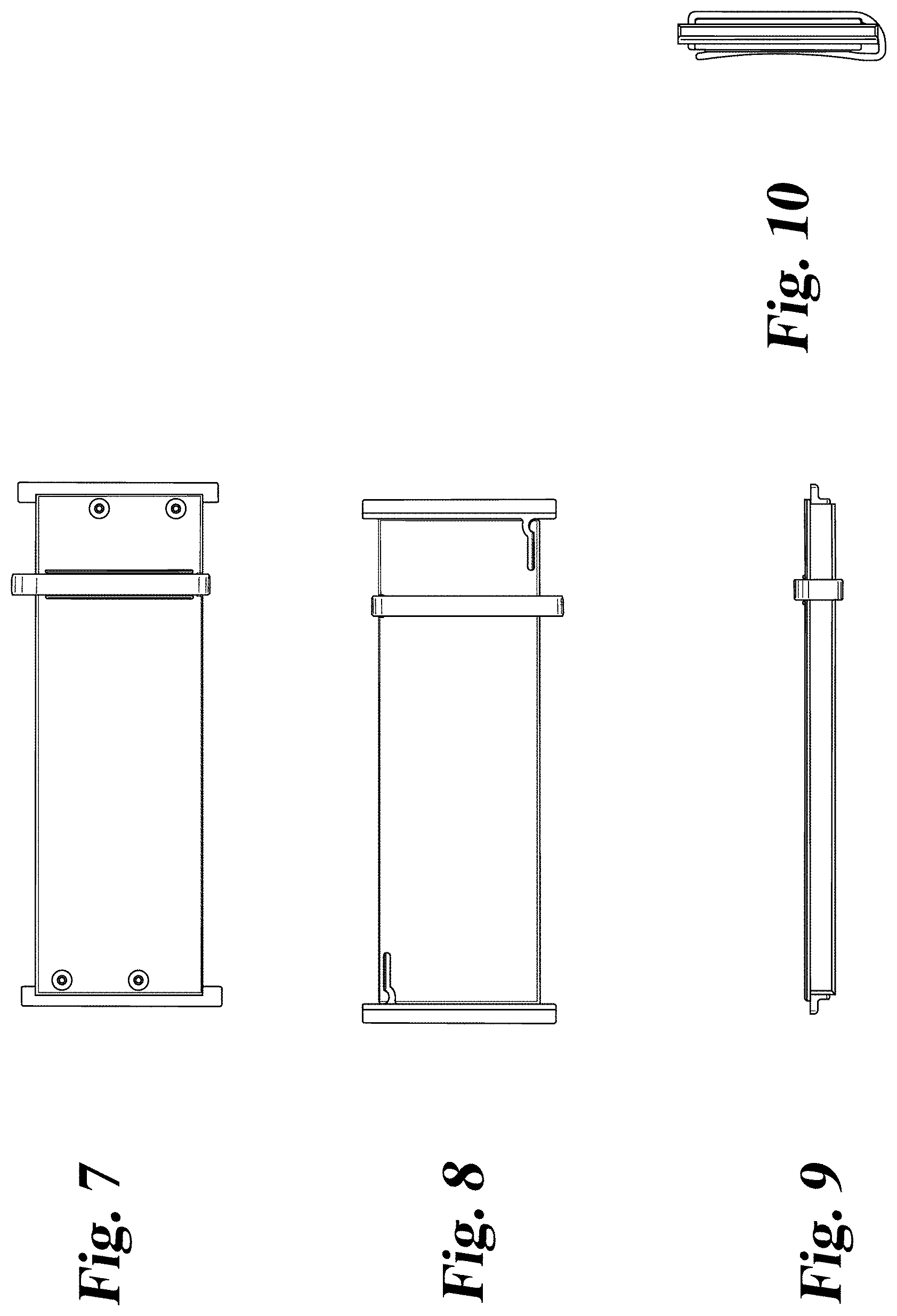
FIG. 6 is a perspective view of the ribbon measuring tool of FIG. 1 in a collapsed configuration.
FIG. 7 is a top view of the ribbon measuring tool of FIG. 6.
FIG. 8 is a bottom view of the ribbon measuring tool of FIG. 6.
FIG. 9 is a side view of the ribbon measuring tool of FIG. 6, the opposite side is a mirror image.
FIG. 10 is an end view of the ribbon measuring tool of FIG. 6, the opposite end is a mirror image; and,
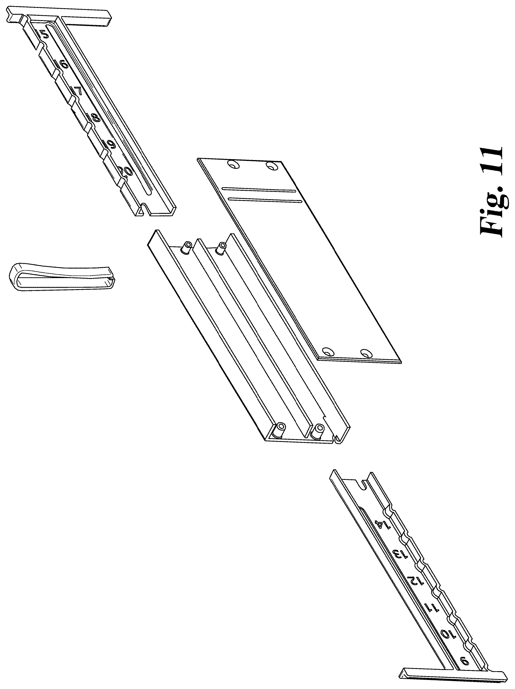
FIG. 11 is an exploded perspective view of the ribbon measuring tool of FIG. 1.
* * * * *
References
D00000
D00001
D00002
D00003
D00004
D00005
XML
uspto.report is an independent third-party trademark research tool that is not affiliated, endorsed, or sponsored by the United States Patent and Trademark Office (USPTO) or any other governmental organization. The information provided by uspto.report is based on publicly available data at the time of writing and is intended for informational purposes only.
While we strive to provide accurate and up-to-date information, we do not guarantee the accuracy, completeness, reliability, or suitability of the information displayed on this site. The use of this site is at your own risk. Any reliance you place on such information is therefore strictly at your own risk.
All official trademark data, including owner information, should be verified by visiting the official USPTO website at www.uspto.gov. This site is not intended to replace professional legal advice and should not be used as a substitute for consulting with a legal professional who is knowledgeable about trademark law.