Roller device
Lombardo , et al. April 19, 2
U.S. patent number D949,360 [Application Number D/706,193] was granted by the patent office on 2022-04-19 for roller device. This patent grant is currently assigned to Church & Dwight Co., Inc.. The grantee listed for this patent is Church & Dwight Co., Inc.. Invention is credited to LoriAnn Lombardo, Aaron Szymanski.


View All Diagrams
| United States Patent | D949,360 |
| Lombardo , et al. | April 19, 2022 |
Roller device
Claims
CLAIM The ornamental design for a roller device, as shown and described.
| Inventors: | Lombardo; LoriAnn (East Hanover, NJ), Szymanski; Aaron (Thomaston, CT) | ||||||||||
|---|---|---|---|---|---|---|---|---|---|---|---|
| Applicant: |
|
||||||||||
| Assignee: | Church & Dwight Co., Inc.
(Princeton, NJ) |
||||||||||
| Appl. No.: | D/706,193 | ||||||||||
| Filed: | September 18, 2019 |
| Current U.S. Class: | D24/211 |
| Current International Class: | 2803 |
| Field of Search: | ;D24/200,211,212,213,214,215 ;D4/122 |
References Cited [Referenced By]
U.S. Patent Documents
| 622350 | April 1899 | Hans |
| 926245 | June 1909 | Coon |
| 1270635 | June 1918 | Ljungstrom |
| 1744423 | January 1930 | Toadvine |
| 1923317 | August 1933 | Lipsner |
| 1947042 | February 1934 | Gennan |
| 2057396 | October 1936 | Seidel |
| D114731 | May 1939 | Tresenberg |
| 2472385 | June 1949 | Rollman |
| 2787261 | April 1957 | McDonald et al. |
| D206258 | November 1966 | Roth |
| 4813404 | March 1989 | Vallis |
| 4884560 | December 1989 | Kuracina |
| D306524 | March 1990 | Marshall |
| 5127395 | July 1992 | Bontemps |
| 5152281 | October 1992 | Koll |
| D336163 | June 1993 | Chien-Min |
| 5267399 | December 1993 | Johnston |
| D352130 | November 1994 | Zierhut |
| 5666963 | September 1997 | Swenson et al. |
| D385060 | October 1997 | Burrell |
| D414875 | October 1999 | Sirois et al. |
| 6648904 | November 2003 | Altshuler et al. |
| D483571 | December 2003 | Khubani |
| D498397 | November 2004 | Mitchell |
| D549834 | August 2007 | Huang |
| 7481783 | January 2009 | Kelley |
| D661168 | June 2012 | Furling |
| D661491 | June 2012 | Bunnag |
| D671747 | December 2012 | Guyton |
| D671748 | December 2012 | Guyton |
| D676975 | February 2013 | Bickford |
| D677391 | March 2013 | Bickford |
| D677392 | March 2013 | Bickford |
| D678540 | March 2013 | Bickford |
| D678541 | March 2013 | Bickford |
| D678542 | March 2013 | Bickford |
| D690944 | October 2013 | Lee |
| D706981 | June 2014 | Clough |
| D781498 | March 2017 | Pel |
| D781499 | March 2017 | Pel |
| D820522 | June 2018 | Colin |
| D824596 | July 2018 | Gobber |
| D829919 | October 2018 | Davis |
| D841176 | February 2019 | Gaquiere |
| D849259 | May 2019 | Gaquiere |
| D863580 | October 2019 | Lee |
| D863581 | October 2019 | Lee |
| D865201 | October 2019 | Gaquiere |
| D865202 | October 2019 | Gaquiere |
| D865203 | October 2019 | Eschbach |
| D865293 | October 2019 | Adams |
| D890941 | July 2020 | Gaquiere |
| D895823 | September 2020 | Khubani |
| 2005/0187498 | August 2005 | Miller |
| 2011/0125067 | May 2011 | Filho |
| 2012/0109041 | May 2012 | Munz |
| 2013/0048011 | February 2013 | Bickford |
| 2015/0057579 | February 2015 | Martinez |
| 2015/0374409 | December 2015 | Chopdat |
| 55/1994-0001 | Feb 1994 | AT | |||
| 125274 | May 1945 | AU | |||
| 2101825 | Feb 1995 | CA | |||
| 2061052 | Aug 1990 | CN | |||
| 2236303 | Oct 1996 | CN | |||
| 2239494 | Nov 1996 | CN | |||
| 2272286 | Jan 1998 | CN | |||
| 2278466 | Apr 1998 | CN | |||
| 2292552 | Sep 1998 | CN | |||
| 2413685 | Jan 2001 | CN | |||
| 1454584 | Nov 2003 | CN | |||
| 300779815 | May 2008 | CN | |||
| 302002689 | Jul 2012 | CN | |||
| 302002753 | Jul 2012 | CN | |||
| 203073458 | Jul 2013 | CN | |||
| 302562252 | Sep 2013 | CN | |||
| 302621013 | Oct 2013 | CN | |||
| 302727467 | Jan 2014 | CN | |||
| 203436539 | Feb 2014 | CN | |||
| 303084499 | Jan 2015 | CN | |||
| 303171515 | Apr 2015 | CN | |||
| 303781867 | Aug 2016 | CN | |||
| 303798174 | Aug 2016 | CN | |||
| 304147157 | May 2017 | CN | |||
| 304433868 | Dec 2017 | CN | |||
| 304510814 | Feb 2018 | CN | |||
| 304977058 | Jan 2019 | CN | |||
| 345284 | Dec 1921 | DE | |||
| M9305491-0001 | Apr 1994 | DE | |||
| 001322069-000 | Apr 2012 | EM | |||
| 004068971-000 | Jul 2017 | EM | |||
| 0667138 | Aug 1995 | EP | |||
| 1797847 | Jun 2007 | EP | |||
| 2493350 | May 2015 | EP | |||
| 191201630 | Oct 1912 | GB | |||
| 2036141 | Apr 1994 | GB | |||
| 2036347 | Jun 1994 | GB | |||
| 2036348 | Jun 1994 | GB | |||
| 2538219 | Nov 2016 | GB | |||
| H07106216 | Nov 1995 | JP | |||
| H1033609 | Feb 1998 | JP | |||
| D1485808 | Dec 2013 | JP | |||
| D1600550 | Mar 2018 | JP | |||
| 300267784.0000 | Oct 2000 | KR | |||
| 2020000020252 | Nov 2000 | KR | |||
| 200243032 | Oct 2001 | KR | |||
| 300710897.0000 | Oct 2013 | KR | |||
| 300829518.0000 | Dec 2015 | KR | |||
| 300979290.0000 | Nov 2018 | KR | |||
Other References
|
Amazon, "Finishing Touch Flawless Facial Massager", Oct. 3, 2020. https://www.amazon.com/Finishing-Touch-Flawless-Facial-Massage/dp/B08DXVZ- 6QP/ref=cm_cr_arp_d_product_top?ie=UTF8. Shwon on p. 1. (Year: 2020). cited by examiner . Flawlessbeauty, "Flawless Ice Roller", Dec. 14, 2020. https://www.flawlessbeauty.com/ICE.dtm. Shown on p. 1. (Year: 2020). cited by examiner. |
Primary Examiner: Ramirez; Cynthia
Assistant Examiner: Maharajh; Michael A
Attorney, Agent or Firm: Womble Bond Dickinson (US) LLP
Description
FIG. 1 is a front perspective view of a first embodiment of a roller device showing our new design;
FIG. 2 is a front view of the roller device;
FIG. 3 is a back view of the roller device;
FIG. 4 is a side view of the roller device;
FIG. 5 is another side view of the roller device;
FIG. 6 is another side view of the roller device;
FIG. 7 is another side view of the roller device;
FIG. 8 is a top plan view of the roller device;
FIG. 9 is a bottom plan view of the roller device;
FIG. 10 is a front perspective view of a second embodiment of a roller device;
FIG. 11 is a front view of the roller device;
FIG. 12 is a back view of the roller device;
FIG. 13 is a side view of the roller device;
FIG. 14 is another side view of the roller device;
FIG. 15 is another side view of the roller device;
FIG. 16 is another side view of the roller device;
FIG. 17 is a top plan view of the roller device;
FIG. 18 is a bottom plan view of the roller device;
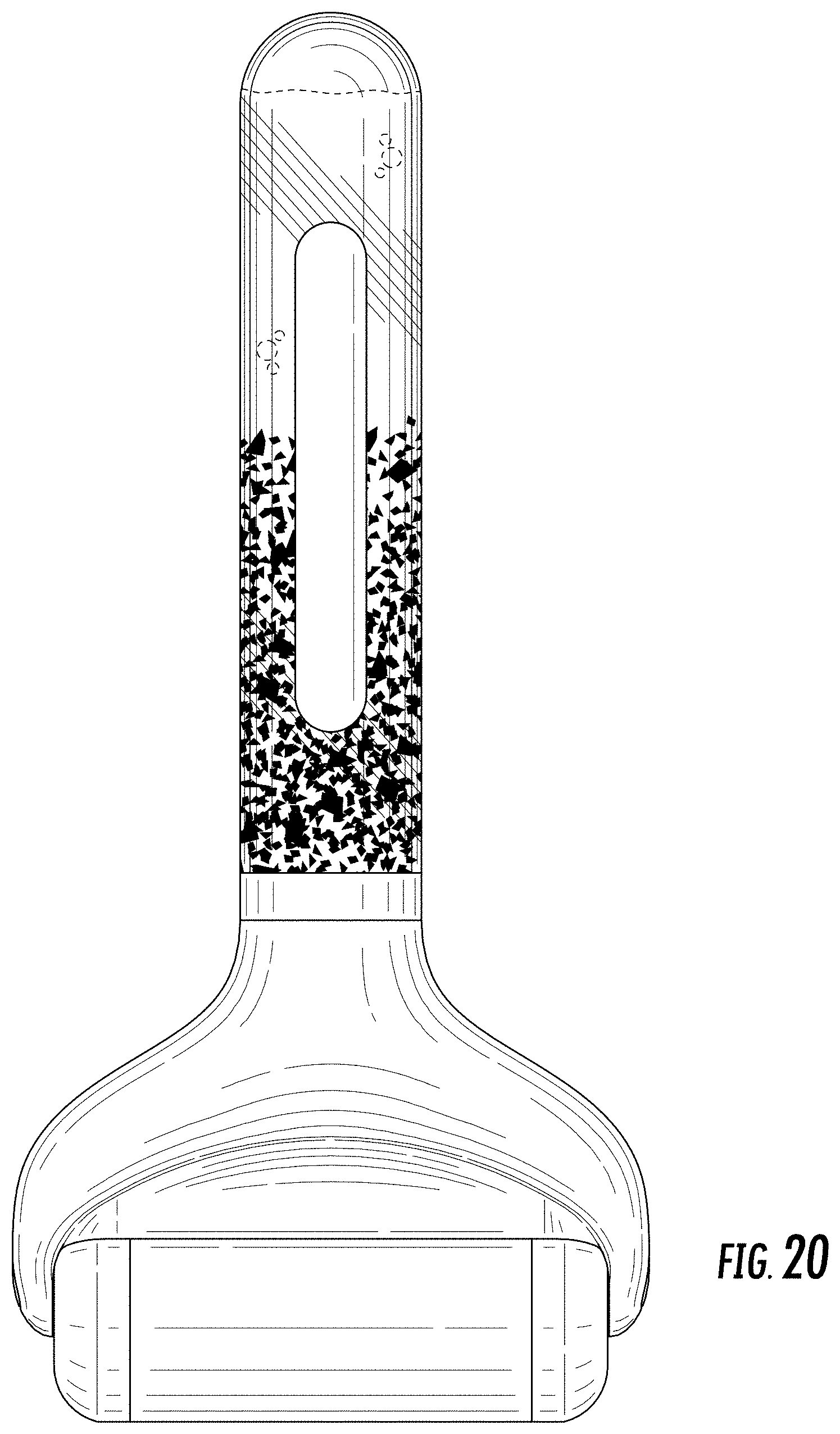
FIG. 19 is a front perspective view of a third embodiment of a roller device;
FIG. 20 is a front view of the roller device;
FIG. 21 is a back view of the roller device;
FIG. 22 is a side view of the roller device;
FIG. 23 is another side view of the roller device;
FIG. 24 is another side view of the roller device;
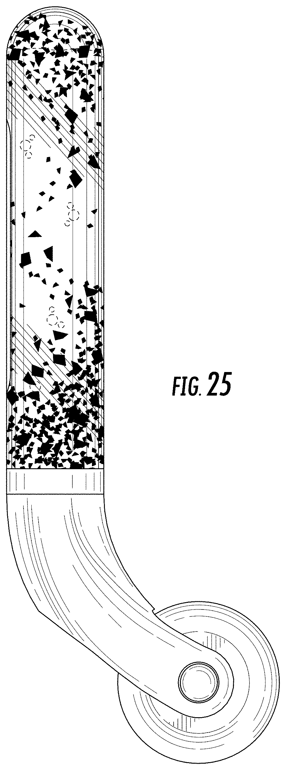
FIG. 25 is another view of the roller device;
FIG. 26 is a top plan view of the roller device;
FIG. 27 is a bottom plan view of the roller device;
FIG. 28 is a front perspective view of a fourth embodiment of a roller device;
FIG. 29 is a front view of the roller device;
FIG. 30 is a back view of the roller device;
FIG. 31 is a side view of the roller device;
FIG. 32 is another side view of the roller device;
FIG. 33 is another side view of the roller device;
FIG. 34 is another side view of the roller device;
FIG. 35 is a top plan view of the roller device; and,
FIG. 36 is a bottom plan view of the roller device.
The particles shown in the handle of the roller device are movable and transition based upon the position of the device. The broken lines in the drawings are for the purpose of illustrating portions of the roller device, which form no part of the claimed design.
* * * * *
References
D00000
D00001
D00002
D00003
D00004
D00005
D00006
D00007
D00008
D00009
D00010
D00011
D00012

D00013

D00014

D00015

D00016

D00017

D00018
D00019

D00020

D00021

D00022

D00023
D00024

D00025

D00026

D00027

D00028

D00029

D00030

D00031

D00032

XML
uspto.report is an independent third-party trademark research tool that is not affiliated, endorsed, or sponsored by the United States Patent and Trademark Office (USPTO) or any other governmental organization. The information provided by uspto.report is based on publicly available data at the time of writing and is intended for informational purposes only.
While we strive to provide accurate and up-to-date information, we do not guarantee the accuracy, completeness, reliability, or suitability of the information displayed on this site. The use of this site is at your own risk. Any reliance you place on such information is therefore strictly at your own risk.
All official trademark data, including owner information, should be verified by visiting the official USPTO website at www.uspto.gov. This site is not intended to replace professional legal advice and should not be used as a substitute for consulting with a legal professional who is knowledgeable about trademark law.