Sample holder
Motomura , et al. June 1, 2
U.S. patent number D921,220 [Application Number D/759,767] was granted by the patent office on 2021-06-01 for sample holder. This patent grant is currently assigned to Sumitomo Electric Industries, Ltd.. The grantee listed for this patent is Sumitomo Electric Industries, Ltd.. Invention is credited to Akinori Kimura, Asako Motomura, Hiroshi Suganuma, Yoko Sugiyama.


View All Diagrams
| United States Patent | D921,220 |
| Motomura , et al. | June 1, 2021 |
Sample holder
Claims
CLAIM The ornamental design for a sample holder, as shown and described.
| Inventors: | Motomura; Asako (Osaka, JP), Kimura; Akinori (Osaka, JP), Sugiyama; Yoko (Osaka, JP), Suganuma; Hiroshi (Osaka, JP) | ||||||||||
|---|---|---|---|---|---|---|---|---|---|---|---|
| Applicant: |
|
||||||||||
| Assignee: | Sumitomo Electric Industries,
Ltd. (Osaka, JP) |
||||||||||
| Appl. No.: | D/759,767 | ||||||||||
| Filed: | November 25, 2020 |
Related U.S. Patent Documents
| Application Number | Filing Date | Patent Number | Issue Date | ||
|---|---|---|---|---|---|
| 29684853 | Mar 25, 2019 | ||||
Foreign Application Priority Data
| Sep 25, 2018 [JP] | 2018-020814 | |||
| Sep 25, 2018 [JP] | 2018-020815 | |||
| Current U.S. Class: | D24/227; D24/229 |
| Current International Class: | 2402 |
| Field of Search: | ;D24/187,216,223-230 ;D3/203.1,203.3 ;D9/456,748,749,755,756,759 |
References Cited [Referenced By]
U.S. Patent Documents
| D224671 | August 1972 | Eddy |
| D242154 | November 1976 | Goy |
| D242654 | December 1976 | Rawls |
| D264245 | May 1982 | Olsen |
| D335348 | May 1993 | Frenkel |
| D360264 | July 1995 | Wolff |
| D367932 | March 1996 | Lim |
| D416330 | November 1999 | Brown |
| D438632 | March 2001 | Miller |
| D481133 | October 2003 | Blouin |
| D767409 | September 2016 | Nickell |
| D786448 | May 2017 | Ohsaka |
| D787086 | May 2017 | Ohsaka |
| D787699 | May 2017 | Ohsaka |
| D800915 | October 2017 | Livingston |
| D808039 | January 2018 | Self |
| D809154 | January 2018 | Livingston |
| D832456 | October 2018 | Self |
| D838380 | January 2019 | Self |
| D851274 | June 2019 | Gomi |
| D871234 | December 2019 | Grove |
| 2018/0224177 | August 2018 | Gaines |
| 1346184 | Jul 2009 | JP | |||
| 3020180009767 | Feb 2018 | KR | |||
Other References
|
Ampola de Plexiglass Stand Suporte para Garrafa de Amostra 50 Buracos Tamanho Dos Poros 11/12.5/17/19/23mm Injec{hacek over (a)}ao Garrafa Rack Para 1/2/5ml/10ml/20ml. Online, published date unknown. Retrieved on Feb. 4, 2021 from URL: https://pt.aliexpress.com/item/32834220736.html?aff_fsk=_pwyiuAT&aff_plat- form=api-new-link-genera. cited by examiner. |
Primary Examiner: Hattan; Susan Bennett
Assistant Examiner: Agilee; Omeed
Attorney, Agent or Firm: Baker Botts L.L.P. Sartori; Michael A.
Description
FIG. 1 is a left perspective view of the present invention.
FIG. 2 is a right perspective view thereof.
FIG. 3 is a front view thereof.
FIG. 4 is a rear view thereof.
FIG. 5 is a top plan view thereof.
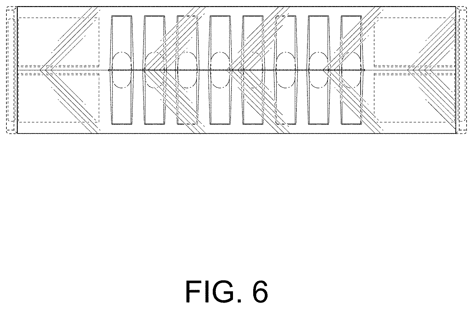
FIG. 6 is a bottom plan view thereof.
FIG. 7 is a right side view thereof.
FIG. 8 is a left side view thereof.
FIG. 9 is a sectional view taken along the line 9-9 of the sample holder of FIG. 5.
FIG. 10 is an enlarged sectional view taken along the line 10-10 of the sample holder of FIG. 3.
FIG. 11 is an enlarged sectional view taken along the line 11-11 of the sample holder of FIG. 3; and,
FIG. 12 is a sectional view taken along the line 12-12 of the sample holder of FIG. 3.
The features shown in broken lines depict environmental subject matter only and form no part of the claimed design.
The dot dash dot broken lines depict the boundaries of the claim and form no part thereof.
* * * * *
References
D00000
D00001
D00002
D00003
D00004
D00005
D00006
D00007
D00008
D00009
D00010
D00011
D00012

XML
uspto.report is an independent third-party trademark research tool that is not affiliated, endorsed, or sponsored by the United States Patent and Trademark Office (USPTO) or any other governmental organization. The information provided by uspto.report is based on publicly available data at the time of writing and is intended for informational purposes only.
While we strive to provide accurate and up-to-date information, we do not guarantee the accuracy, completeness, reliability, or suitability of the information displayed on this site. The use of this site is at your own risk. Any reliance you place on such information is therefore strictly at your own risk.
All official trademark data, including owner information, should be verified by visiting the official USPTO website at www.uspto.gov. This site is not intended to replace professional legal advice and should not be used as a substitute for consulting with a legal professional who is knowledgeable about trademark law.