Filter
Hauville , et al. June 1, 2
U.S. patent number D921,176 [Application Number D/694,086] was granted by the patent office on 2021-06-01 for filter. The grantee listed for this patent is FIPAK Research And Development Company. Invention is credited to Antoine Hauville, Stephane Hauville, Cedric Herry.


| United States Patent | D921,176 |
| Hauville , et al. | June 1, 2021 |
Filter
Claims
CLAIM The ornamental design for a filter, as shown and described.
| Inventors: | Hauville; Stephane (Rowley, MA), Hauville; Antoine (La Londe, FR), Herry; Cedric (Val de Reuil, FR) | ||||||||||
|---|---|---|---|---|---|---|---|---|---|---|---|
| Applicant: |
|
||||||||||
| Appl. No.: | D/694,086 | ||||||||||
| Filed: | June 7, 2019 |
| Current U.S. Class: | D23/365 |
| Current International Class: | 2304 |
| Field of Search: | ;D23/209,235,341,358,363-365 ;D15/5 ;D7/368,669 ;D24/122 |
References Cited [Referenced By]
U.S. Patent Documents
| 2243916 | June 1941 | Mueller |
| D159487 | August 1950 | Jaye |
| D211790 | July 1968 | Murray |
| D285830 | September 1986 | Daily et al. |
| D288519 | March 1987 | Taylor |
| D325254 | April 1992 | Ruuskanen |
| 5443625 | August 1995 | Schaffhausen |
| D373348 | September 1996 | Carlson |
| D383881 | September 1997 | Gudmundsson |
| D396097 | July 1998 | Thomas et al. |
| D402361 | December 1998 | Nepsund et al. |
| 6284011 | September 2001 | Chiang et al. |
| 6321034 | November 2001 | Jones-Lawlor et al. |
| D453822 | February 2002 | Meeks et al. |
| 6428592 | August 2002 | Chase et al. |
| 6494199 | December 2002 | Zia et al. |
| D483844 | December 2003 | Yamamoto et al. |
| D486485 | February 2004 | Dodson |
| D502254 | February 2005 | Smith et al. |
| D534262 | December 2006 | Rho |
| D548826 | August 2007 | Katta |
| D558317 | December 2007 | Francisquini |
| 7462220 | December 2008 | Farmer |
| D605274 | December 2009 | Kawano |
| D605275 | December 2009 | Kawano |
| 7749303 | July 2010 | Wright |
| D636857 | April 2011 | Jacques et al. |
| D638529 | May 2011 | Gedcke et al. |
| D638857 | May 2011 | Garrison et al. |
| D645130 | September 2011 | Goldstein et al. |
| 8021455 | September 2011 | Adamek |
| D653320 | January 2012 | Watanabe et al. |
| D661696 | June 2012 | Takada |
| D680636 | April 2013 | Ching |
| D689995 | September 2013 | Dios |
| D725254 | March 2015 | Roblin |
| D725760 | March 2015 | Nakagawa |
| 8986427 | March 2015 | Hauville et al. |
| D741463 | October 2015 | Hauville |
| D754315 | April 2016 | Morin |
| D778419 | February 2017 | Poindexter |
| D831157 | October 2018 | Kronk |
| D878533 | March 2020 | Gabriel |
| 2001/0049927 | December 2001 | Toepel |
| 2004/0194441 | October 2004 | Kirsch |
| 2006/0053759 | March 2006 | Winters |
| 2009/0044703 | February 2009 | Bias et al. |
| 2009/0075582 | March 2009 | Wilkerson |
| 2009/0311951 | December 2009 | Walkinshaw |
| 2010/0294134 | November 2010 | Yokomizo et al. |
| 2012/0087087 | April 2012 | Nicolai et al. |
| 2012/0151889 | June 2012 | Horey |
| 2015/0177721 | June 2015 | Hauville |
| 2 199 695 | Jun 2010 | EP | |||
| WO 2012/167280 | Dec 2012 | WO | |||
Attorney, Agent or Firm: Pandiscio & Pandiscio
Description
FIG. 1 is a top perspective view of the filter;
FIG. 2 is a top view of the filter, taken from the frame of reference of FIG. 1;
FIG. 3 is a bottom view of the filter, taken from the frame of reference of FIG. 1;
FIG. 4 is a side view, in elevation, of the left side of the filter, taken from the frame of reference of FIG. 1;
FIG. 5 is a side view, in elevation, of the right side of the filter, taken from the frame of reference of FIG. 1;
FIG. 6 is a front view of the filter, taken from the frame of reference of FIG. 1;
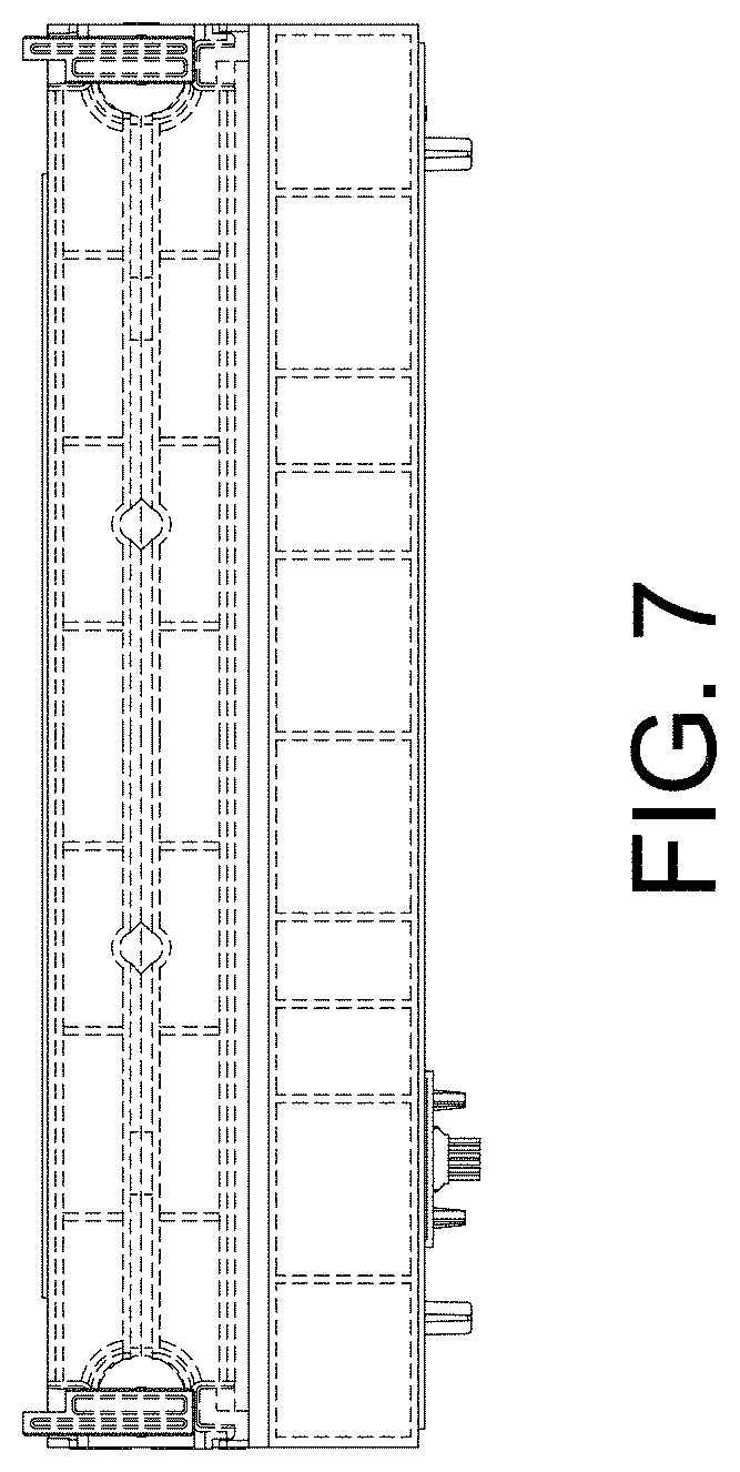
FIG. 7 is a rear view of the filter, taken from the frame of reference of FIG. 1; and,
FIG. 8 is a bottom perspective view of the filter.
The broken lines are included for the purpose of illustrating unclaimed portions of the filter and form no part of the claimed design.
* * * * *
D00000
D00001
D00002
D00003
D00004
D00005
D00006
D00007
D00008
XML
uspto.report is an independent third-party trademark research tool that is not affiliated, endorsed, or sponsored by the United States Patent and Trademark Office (USPTO) or any other governmental organization. The information provided by uspto.report is based on publicly available data at the time of writing and is intended for informational purposes only.
While we strive to provide accurate and up-to-date information, we do not guarantee the accuracy, completeness, reliability, or suitability of the information displayed on this site. The use of this site is at your own risk. Any reliance you place on such information is therefore strictly at your own risk.
All official trademark data, including owner information, should be verified by visiting the official USPTO website at www.uspto.gov. This site is not intended to replace professional legal advice and should not be used as a substitute for consulting with a legal professional who is knowledgeable about trademark law.