Bridge piece
Norton , et al. June 1, 2
U.S. patent number D921,164 [Application Number D/766,416] was granted by the patent office on 2021-06-01 for bridge piece. This patent grant is currently assigned to Cleveland Reclaim Industries, Inc.. The grantee listed for this patent is Cleveland Reclaim Industries, Inc.. Invention is credited to Stephen P. Casteel, Michael W. Jackson, Tom Norton.


| United States Patent | D921,164 |
| Norton , et al. | June 1, 2021 |
Bridge piece
Claims
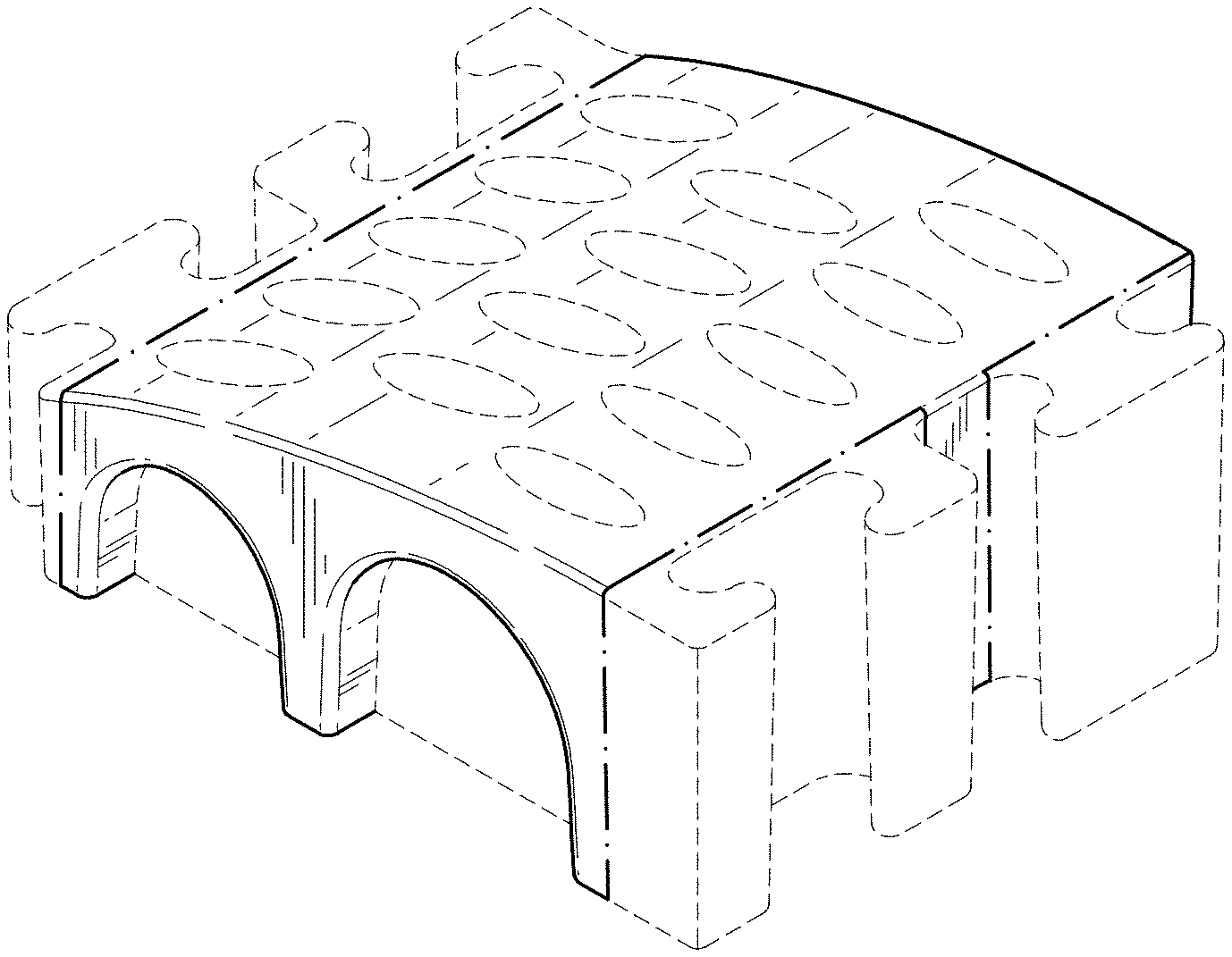
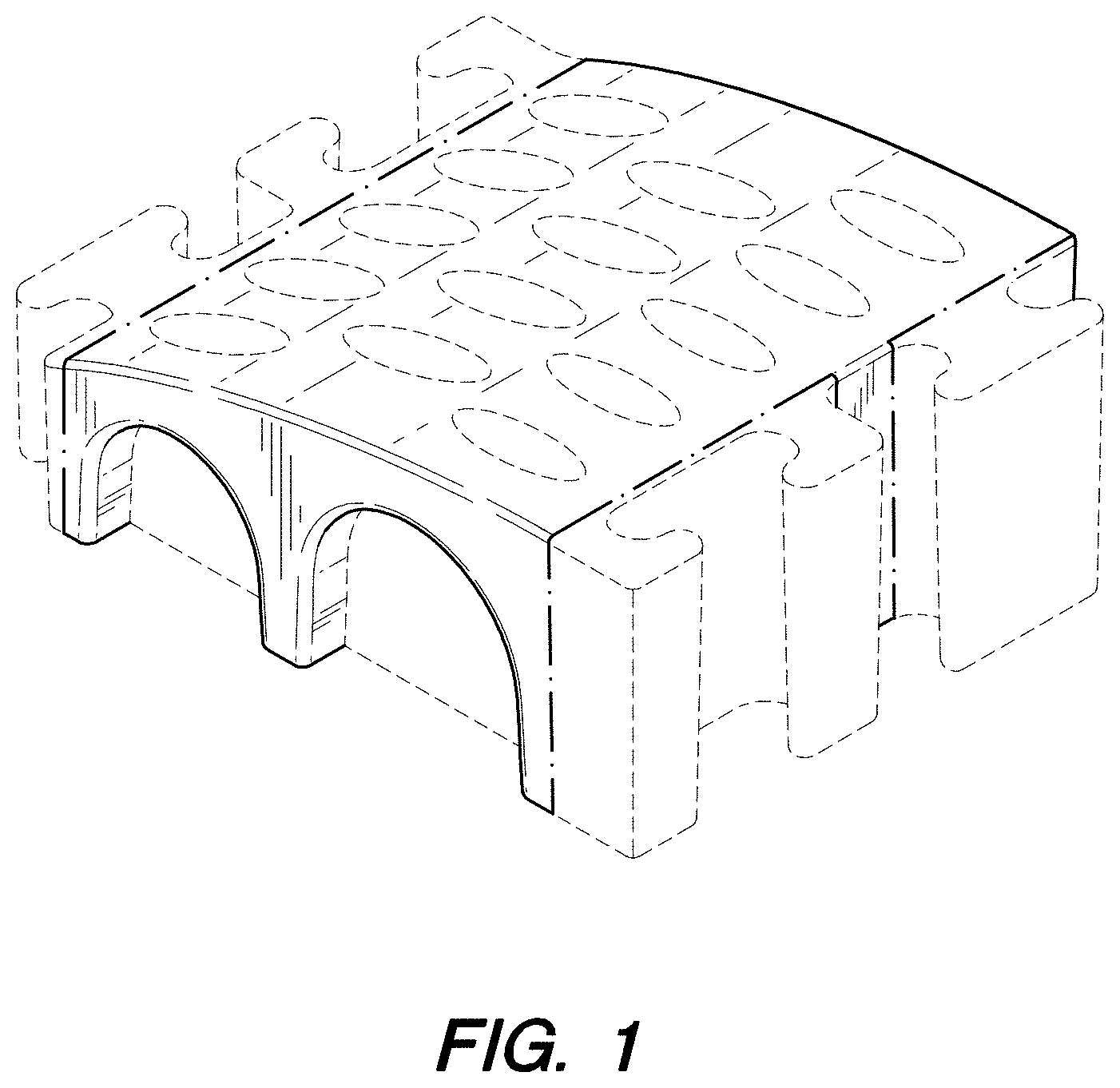
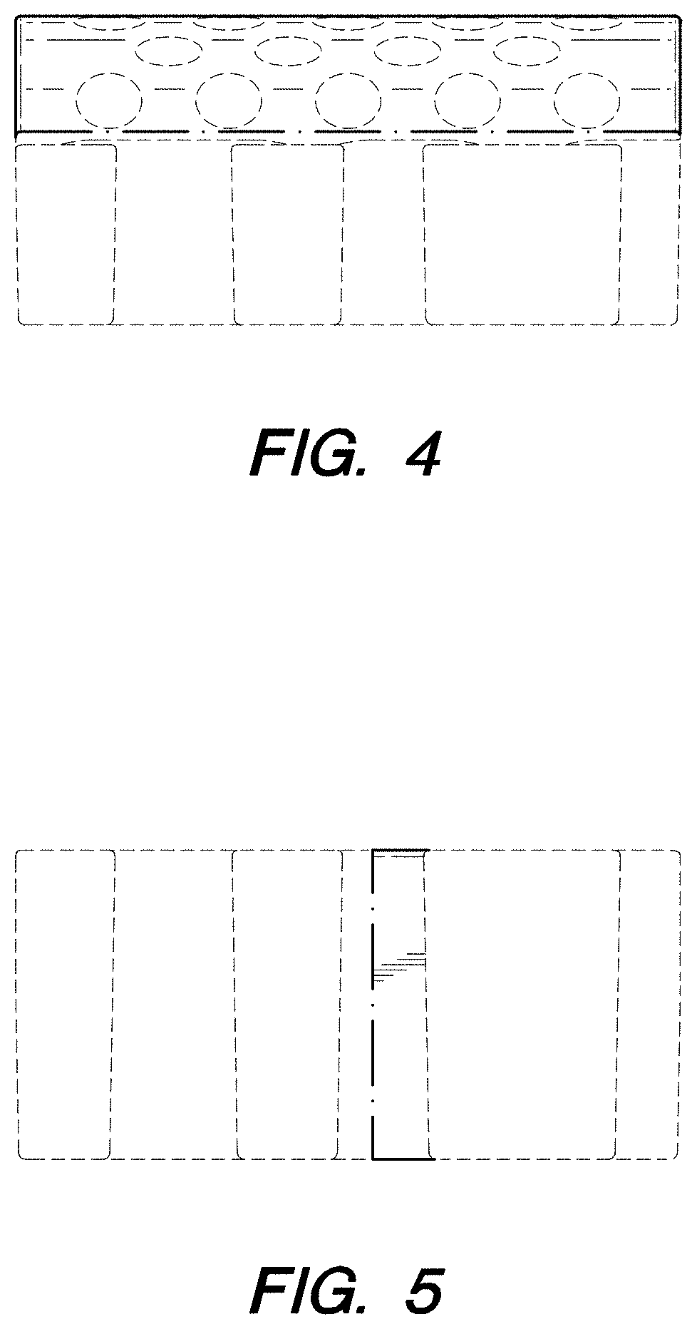
CLAIM We claim the ornamental design for a bridge piece, as shown and described.
| Inventors: | Norton; Tom (Bay Village, OH), Casteel; Stephen P. (Canal Fulton, OH), Jackson; Michael W. (Wooster, OH) | ||||||||||
|---|---|---|---|---|---|---|---|---|---|---|---|
| Applicant: |
|
||||||||||
| Assignee: | Cleveland Reclaim Industries,
Inc. (Lorain, OH) |
||||||||||
| Appl. No.: | D/766,416 | ||||||||||
| Filed: | January 15, 2021 |
Related U.S. Patent Documents
| Application Number | Filing Date | Patent Number | Issue Date | ||
|---|---|---|---|---|---|
| 29679834 | Feb 11, 2019 | D908845 | |||
| 29544094 | Apr 2, 2019 | D844757 | |||
| Current U.S. Class: | D23/259; D25/113 |
| Current International Class: | 2301 |
| Field of Search: | ;D23/259-261,262-266 ;D8/354,396 ;D13/155 ;D34/32 ;D25/123,125,113-118 ;104/275-277 ;404/15 ;138/106,110 |
References Cited [Referenced By]
U.S. Patent Documents
| 72028 | December 1867 | Haase |
| 96559 | November 1869 | Donoghue et al. |
| 679570 | July 1901 | McClurg |
| 982924 | January 1911 | Bardon |
| 1914830 | June 1933 | Kostohris |
| 2166516 | July 1939 | Bainbridge |
| 2539343 | January 1951 | Boose |
| D205277 | July 1966 | Gilchrist |
| 3855752 | December 1974 | Aylon |
| 4101100 | July 1978 | Smith et al. |
| 4370075 | January 1983 | Scales |
| D298464 | November 1988 | Roote |
| D313102 | December 1990 | Cano |
| D370717 | June 1996 | Ziaylek, Jr. et al. |
| 5566622 | October 1996 | Ziaylek, Jr. et al. |
| 5777266 | July 1998 | Herman et al. |
| D415471 | October 1999 | Henry |
| D418818 | January 2000 | Henry |
| 6067681 | May 2000 | Zeinstra et al. |
| D436578 | January 2001 | Henry |
| D437832 | February 2001 | Henry |
| 6202565 | March 2001 | Henry |
| 6287047 | September 2001 | Dufresne |
| D463041 | September 2002 | Dice |
| 6508041 | January 2003 | Boot |
| 6866446 | March 2005 | McAllister et al. |
| 6878881 | April 2005 | Henry |
| D552217 | October 2007 | Norton |
| 7309836 | December 2007 | Lubanski |
| D567913 | April 2008 | Norton |
| 7394025 | July 2008 | Wong |
| D583771 | December 2008 | Lubanski |
| D587159 | February 2009 | Dholakiya |
| 7595450 | September 2009 | Lubanski |
| 8123435 | February 2012 | DeShaw et al. |
| D673658 | January 2013 | Dufresne |
| D688809 | August 2013 | McAllister |
| 8678704 | March 2014 | Smith et al. |
| D705514 | May 2014 | Tai |
| D706513 | June 2014 | LaBarbera et al. |
| D719519 | December 2014 | Mathena |
| D725748 | March 2015 | Lake |
| 1137313 | April 2015 | Hamilton |
| 9059574 | June 2015 | Coffman |
| 9438022 | September 2016 | Lioi |
| D772431 | November 2016 | Norton et al. |
| 9512582 | December 2016 | Hill |
| 9834927 | December 2017 | Huff |
| D815306 | April 2018 | Norton et al. |
| D844757 | April 2019 | Norton et al. |
| D899566 | October 2020 | Norton et al. |
| D906486 | December 2020 | Norton et al. |
| D908845 | January 2021 | Norton et al. |
| 2002/0078513 | June 2002 | Schouest |
| 2007/0277894 | December 2007 | Boone et al. |
| 2010/0282352 | November 2010 | Maue et al. |
| 2010/0303555 | December 2010 | Herse |
| 2013/0048439 | February 2013 | Marcum |
| 105214267 | Sep 2015 | CN | |||
| 485673 | Jul 1938 | GB | |||
| 911043 | Nov 1962 | GB | |||
| 3292910 | Oct 1996 | JP | |||
| 20100036837 | Sep 2008 | KR | |||
Attorney, Agent or Firm: Calfee, Halter & Griswold LLP
Description
FIG. 1 is a front/right/top perspective view of a bridge piece;
FIG. 2 is a front elevational view thereof;
FIG. 3 is a rear elevational view thereof;
FIG. 4 is a left side elevational view thereof;
FIG. 5 is a right side elevational view thereof;
FIG. 6 is a top plan view thereof; and,
FIG. 7 is a bottom plan view thereof.
The dash-dot broken lines and the uniformly broken lines immediately adjacent shaded areas represent the bounds of the claimed design. All other broken lines represent portions of the bridge piece that form no part of the claimed design.
* * * * *
D00000
D00001
D00002
D00003
D00004
XML
uspto.report is an independent third-party trademark research tool that is not affiliated, endorsed, or sponsored by the United States Patent and Trademark Office (USPTO) or any other governmental organization. The information provided by uspto.report is based on publicly available data at the time of writing and is intended for informational purposes only.
While we strive to provide accurate and up-to-date information, we do not guarantee the accuracy, completeness, reliability, or suitability of the information displayed on this site. The use of this site is at your own risk. Any reliance you place on such information is therefore strictly at your own risk.
All official trademark data, including owner information, should be verified by visiting the official USPTO website at www.uspto.gov. This site is not intended to replace professional legal advice and should not be used as a substitute for consulting with a legal professional who is knowledgeable about trademark law.