Battery module connector barrel
Elison , et al. May 25, 2
U.S. patent number D920,251 [Application Number D/683,626] was granted by the patent office on 2021-05-25 for battery module connector barrel. This patent grant is currently assigned to CPS Technology Holdings LLC. The grantee listed for this patent is CPS Technology Holdings LLC. Invention is credited to Richard M. DeKeuster, Nicholas E. Elison.

| United States Patent | D920,251 |
| Elison , et al. | May 25, 2021 |
Battery module connector barrel
Claims
CLAIM The ornamental design for a battery module connector barrel, as shown and described herein.
| Inventors: | Elison; Nicholas E. (Milwaukee, WI), DeKeuster; Richard M. (Racine, WI) | ||||||||||
|---|---|---|---|---|---|---|---|---|---|---|---|
| Applicant: |
|
||||||||||
| Assignee: | CPS Technology Holdings LLC
(New York, NY) |
||||||||||
| Appl. No.: | D/683,626 | ||||||||||
| Filed: | March 14, 2019 |
Related U.S. Patent Documents
| Application Number | Filing Date | Patent Number | Issue Date | ||
|---|---|---|---|---|---|
| 14850728 | Sep 10, 2015 | 10249916 | |||
| Current U.S. Class: | D13/133; D13/119 |
| Current International Class: | 1302 |
| Field of Search: | ;D13/103,107,119,120,133,146,147,153,154,155,156,184 |
References Cited [Referenced By]
U.S. Patent Documents
| D256356 | August 1980 | Lazerson |
| D319813 | September 1991 | Kozono |
| 5127848 | July 1992 | Taguchi |
| D335647 | May 1993 | Hood |
| 5378552 | January 1995 | Dixon, Jr. |
| 5681178 | October 1997 | Kunkle |
| D389457 | January 1998 | Beranek |
| 6312277 | November 2001 | Holub |
| 6372377 | April 2002 | Ovshinsky et al. |
| 6376122 | April 2002 | Cheeseman |
| D475014 | May 2003 | Kano |
| D544843 | June 2007 | Sugita |
| D588990 | March 2009 | Kok |
| D589444 | March 2009 | Kok |
| 7722372 | May 2010 | Matsumoto et al. |
| 7879485 | February 2011 | Yoon et al. |
| 7892011 | February 2011 | Beer |
| 8038450 | October 2011 | Nakagawa |
| 8147280 | April 2012 | Fernandez et al. |
| 8221165 | July 2012 | DeWitte |
| 8237400 | August 2012 | Gamboa et al. |
| 8328581 | December 2012 | DeChazal |
| D675568 | February 2013 | Drew |
| D678203 | March 2013 | Corona |
| 8679666 | March 2014 | Tsukamoto et al. |
| 8808031 | August 2014 | Zhao |
| 9150107 | October 2015 | Ferrel |
| 9321340 | April 2016 | Maskew et al. |
| D765030 | August 2016 | Tyler |
| 9413040 | August 2016 | Murakami et al. |
| D797043 | September 2017 | Akana |
| D803778 | November 2017 | Tononishi |
| D817278 | May 2018 | Tyler |
| 10249916 | April 2019 | Tyler |
| 10439182 | October 2019 | Elison |
| D867993 | November 2019 | DeKeuster |
| 10543795 | January 2020 | DeKeuster |
| D894128 | August 2020 | Somanathapura Ramanna |
| 10819073 | October 2020 | Azad |
| 2001/0018294 | August 2001 | Kameyama |
| 2007/0087266 | April 2007 | Bourke et al. |
| 2012/0308869 | December 2012 | Obasih |
| 2014/0045026 | February 2014 | Fritz |
| 2014/0062493 | March 2014 | Farrell |
| 2014/0327444 | November 2014 | Rollan et al. |
| 2015/0069829 | March 2015 | Dulle et al. |
| 2015/0217707 | August 2015 | Tanigaki |
| 2015/0243946 | August 2015 | Ahn |
| 2016/0043448 | February 2016 | Fritz |
| 2016/0107530 | April 2016 | Roberts et al. |
| 2016/0133908 | May 2016 | Zhao |
| 2016/0197384 | July 2016 | DeKeuster |
| 2016/0226112 | August 2016 | Maskew et al. |
| 103081214 | Feb 2012 | CN | |||
| 103534835 | Jan 2014 | CN | |||
| 0921607 | Jun 1999 | EP | |||
| 2355209 | Aug 2011 | EP | |||
| 9831059 | Jul 1998 | WO | |||
| 2012142284 | Oct 2012 | WO | |||
| 2013188680 | Dec 2013 | WO | |||
Other References
|
PCT/US2016/017918 Search Report and Written Opinion dated May 3, 2016. cited by applicant. |
Primary Examiner: Kearney; Karen E
Assistant Examiner: Chong; Michael
Attorney, Agent or Firm: Boardman & Clark LLP
Description
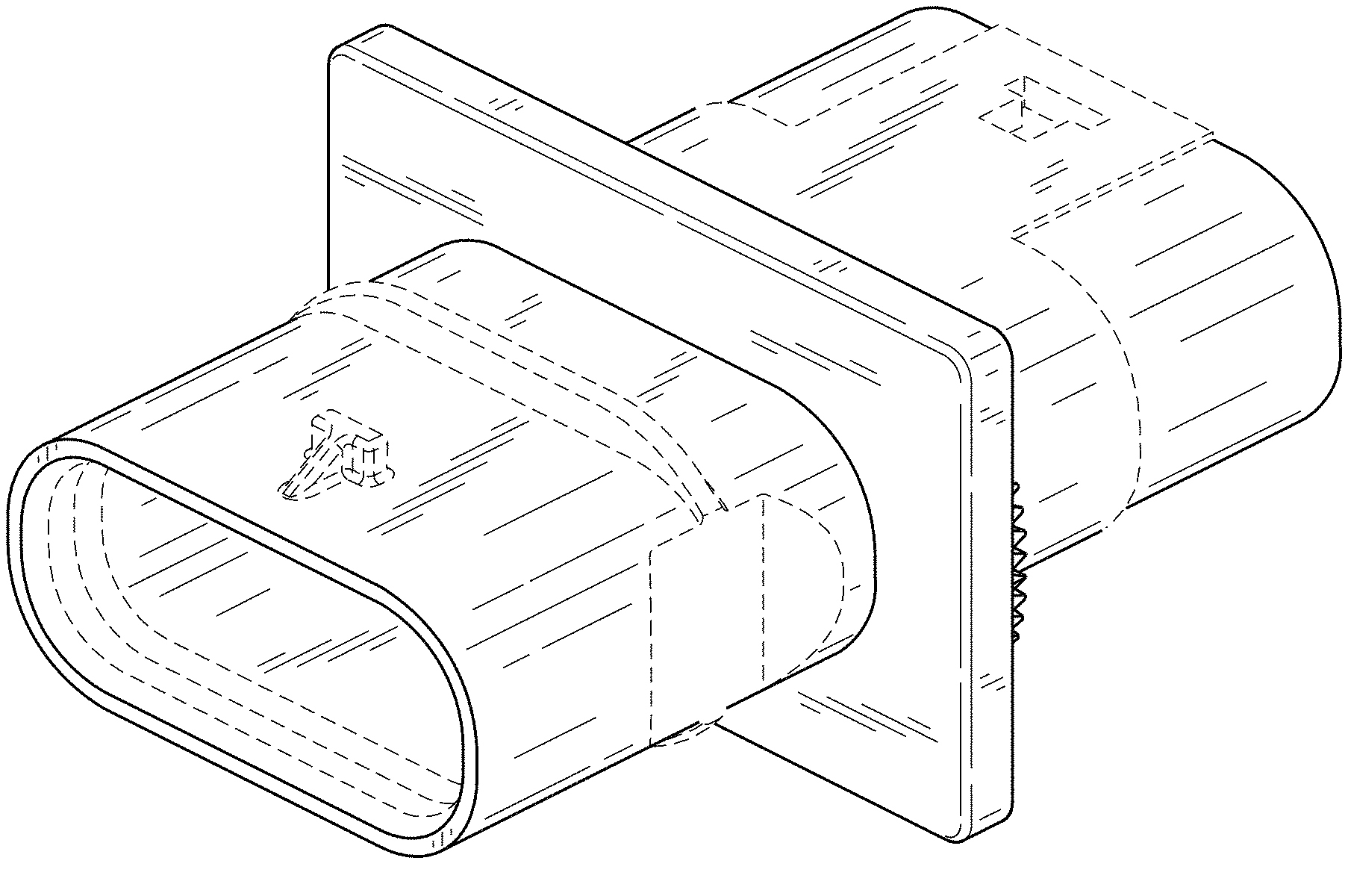
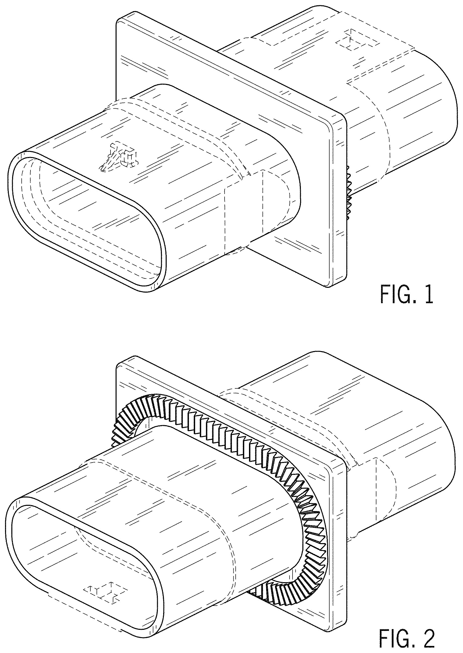
FIG. 1 is a front overhead perspective view of a connector barrel showing our new design;
FIG. 2 is a back overhead perspective view thereof;
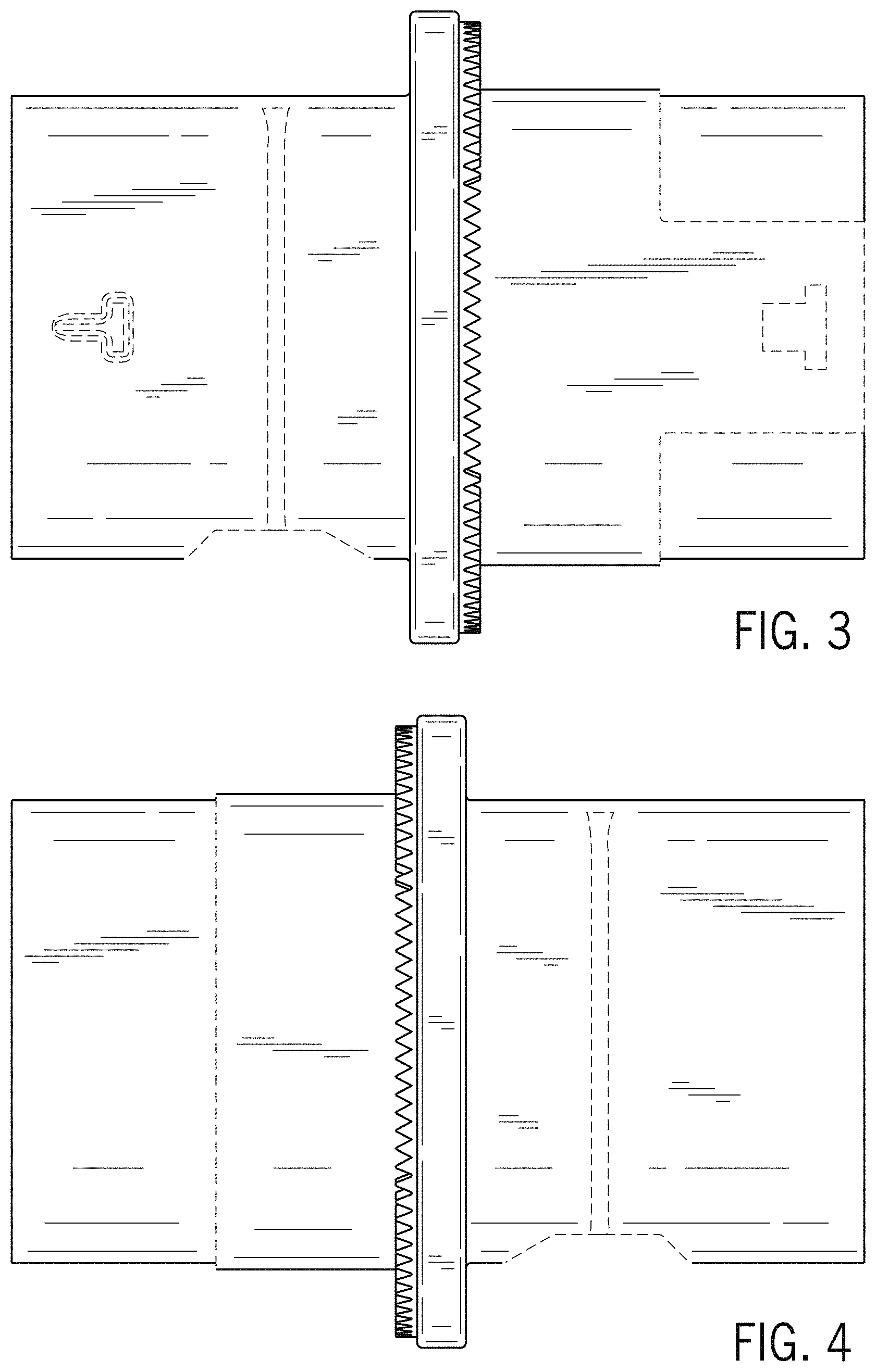
FIG. 3 is a top plan view thereof;
FIG. 4 is a bottom plan view thereof;
FIG. 5 is a right side elevation view thereof;
FIG. 6 is a left side elevation view thereof;
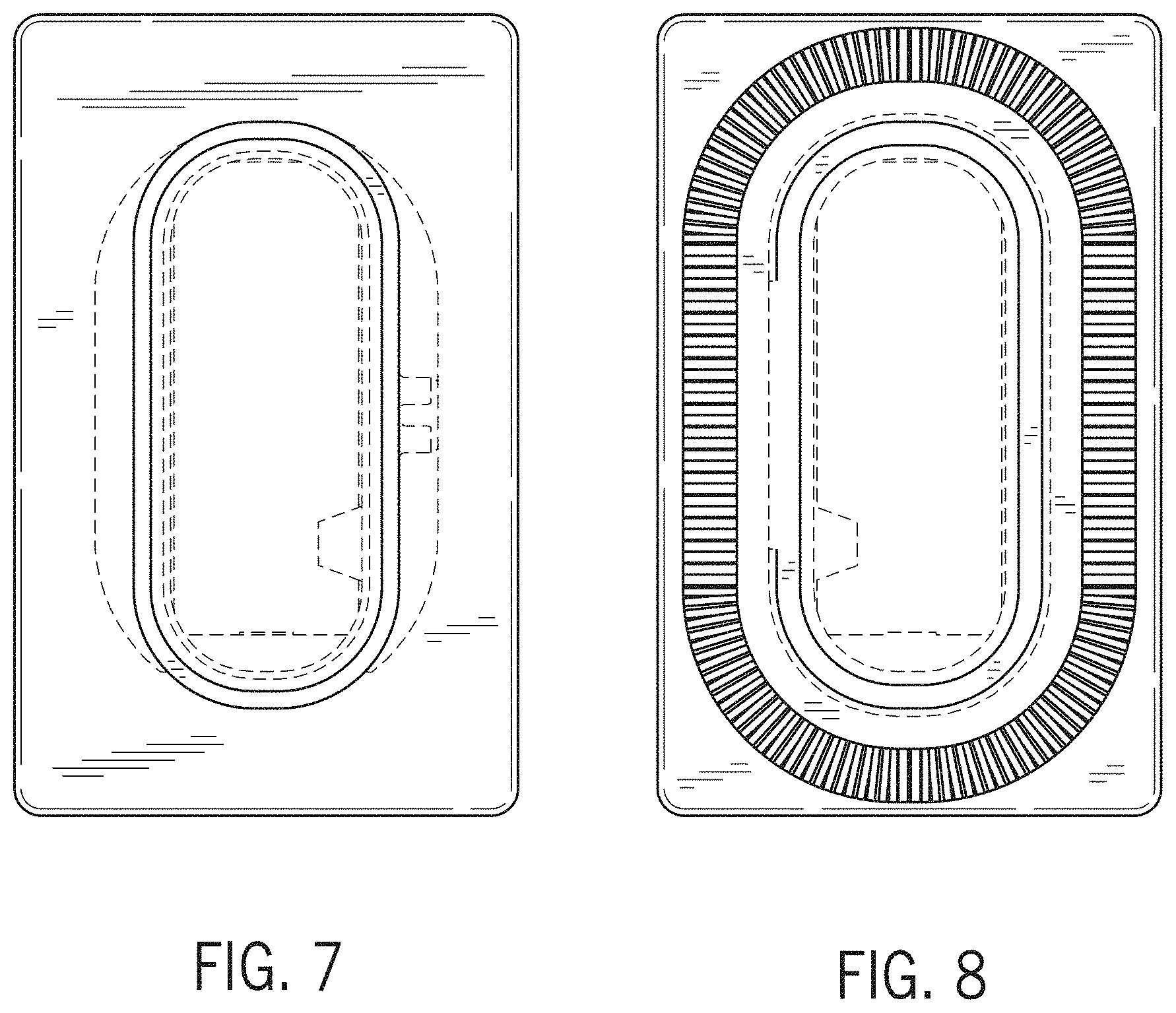
FIG. 7 is a front elevation view thereof; and,
FIG. 8 is a back election view thereof.
The broken line showing of a battery module connector barrel is for the purpose of illustrating portions of the article and forms no part of the claimed design.
* * * * *
D00000
D00001
D00002
D00003
D00004
XML
uspto.report is an independent third-party trademark research tool that is not affiliated, endorsed, or sponsored by the United States Patent and Trademark Office (USPTO) or any other governmental organization. The information provided by uspto.report is based on publicly available data at the time of writing and is intended for informational purposes only.
While we strive to provide accurate and up-to-date information, we do not guarantee the accuracy, completeness, reliability, or suitability of the information displayed on this site. The use of this site is at your own risk. Any reliance you place on such information is therefore strictly at your own risk.
All official trademark data, including owner information, should be verified by visiting the official USPTO website at www.uspto.gov. This site is not intended to replace professional legal advice and should not be used as a substitute for consulting with a legal professional who is knowledgeable about trademark law.