Surgical tool
Schifano , et al. May 11, 2
U.S. patent number D919,087 [Application Number D/653,774] was granted by the patent office on 2021-05-11 for surgical tool. The grantee listed for this patent is Orthocision Inc.. Invention is credited to Steve Anderson, Troy Schifano.


View All Diagrams
| United States Patent | D919,087 |
| Schifano , et al. | May 11, 2021 |
Surgical tool
Claims
CLAIM We claim the ornamental designs for a surgical tool, as shown and described.
| Inventors: | Schifano; Troy (Morgantown, WV), Anderson; Steve (Folsom, CA) | ||||||||||
|---|---|---|---|---|---|---|---|---|---|---|---|
| Applicant: |
|
||||||||||
| Appl. No.: | D/653,774 | ||||||||||
| Filed: | June 19, 2018 |
| Current U.S. Class: | D24/135 |
| Current International Class: | 2404 |
| Field of Search: | ;D24/135 |
References Cited [Referenced By]
U.S. Patent Documents
| 8236032 | August 2012 | Ramsay |
| 8246538 | August 2012 | Gorek |
| 8333770 | December 2012 | Hua |
| 8740912 | June 2014 | Stark |
| 8747407 | June 2014 | Gorek |
| 8870878 | October 2014 | Gorek |
| 8882818 | November 2014 | Vestgaarden |
| 8932210 | January 2015 | Woods |
| 9381045 | July 2016 | Donner et al. |
| 9451986 | September 2016 | Stoffman et al. |
| 9629667 | April 2017 | Petit |
| 10568669 | February 2020 | Reitblat |
| 10702314 | July 2020 | Reitblat |
| D905232 | December 2020 | Schifano |
| 2009/0222044 | September 2009 | Gorek |
| 2009/0222045 | September 2009 | Gorek |
| 2010/0106200 | April 2010 | Stark |
| 2011/0184518 | July 2011 | Trieu |
| 2011/0209821 | September 2011 | Gorek |
| 2013/0184763 | July 2013 | McClintock |
| 2014/0243602 | August 2014 | Gorek |
Other References
|
Everest, Pamphlet of Everest minimally invasive xt spinal system, available online at http://www.innosurge.com/sites/default/files/uploads/surgery-techniques/S- urgical%20Technique%20XT.pdf. cited by applicant. |
Primary Examiner: Hanson; Charles D
Attorney, Agent or Firm: Sierra IP Law, PC Nelson; William K.
Description
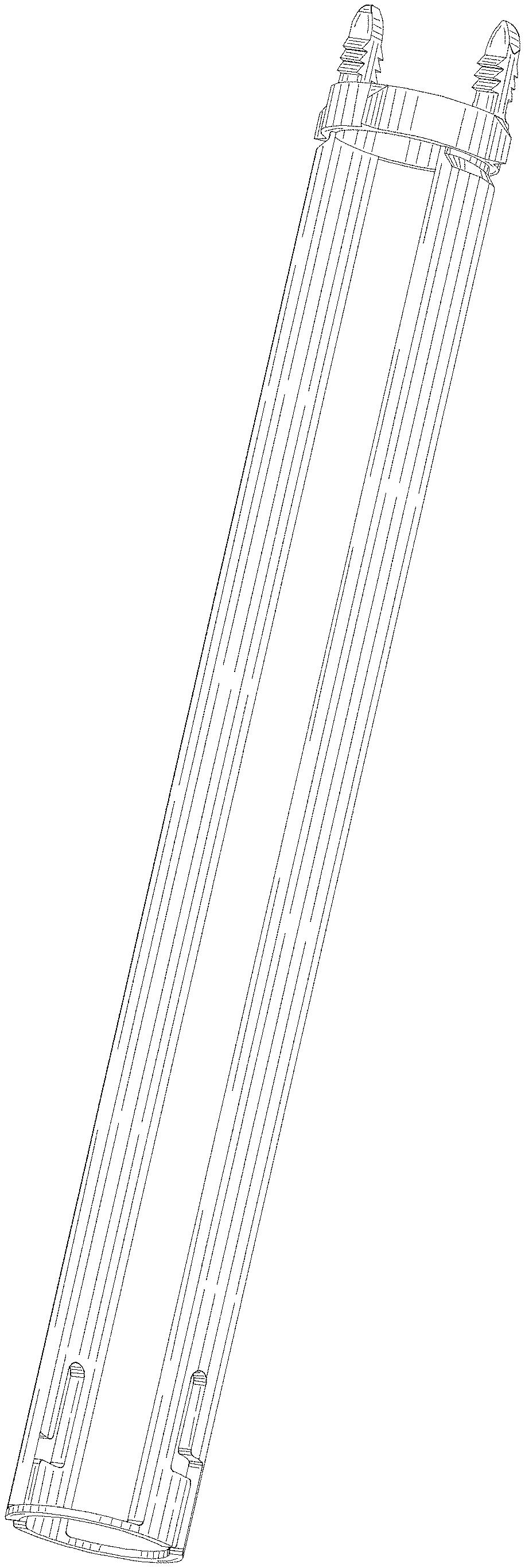
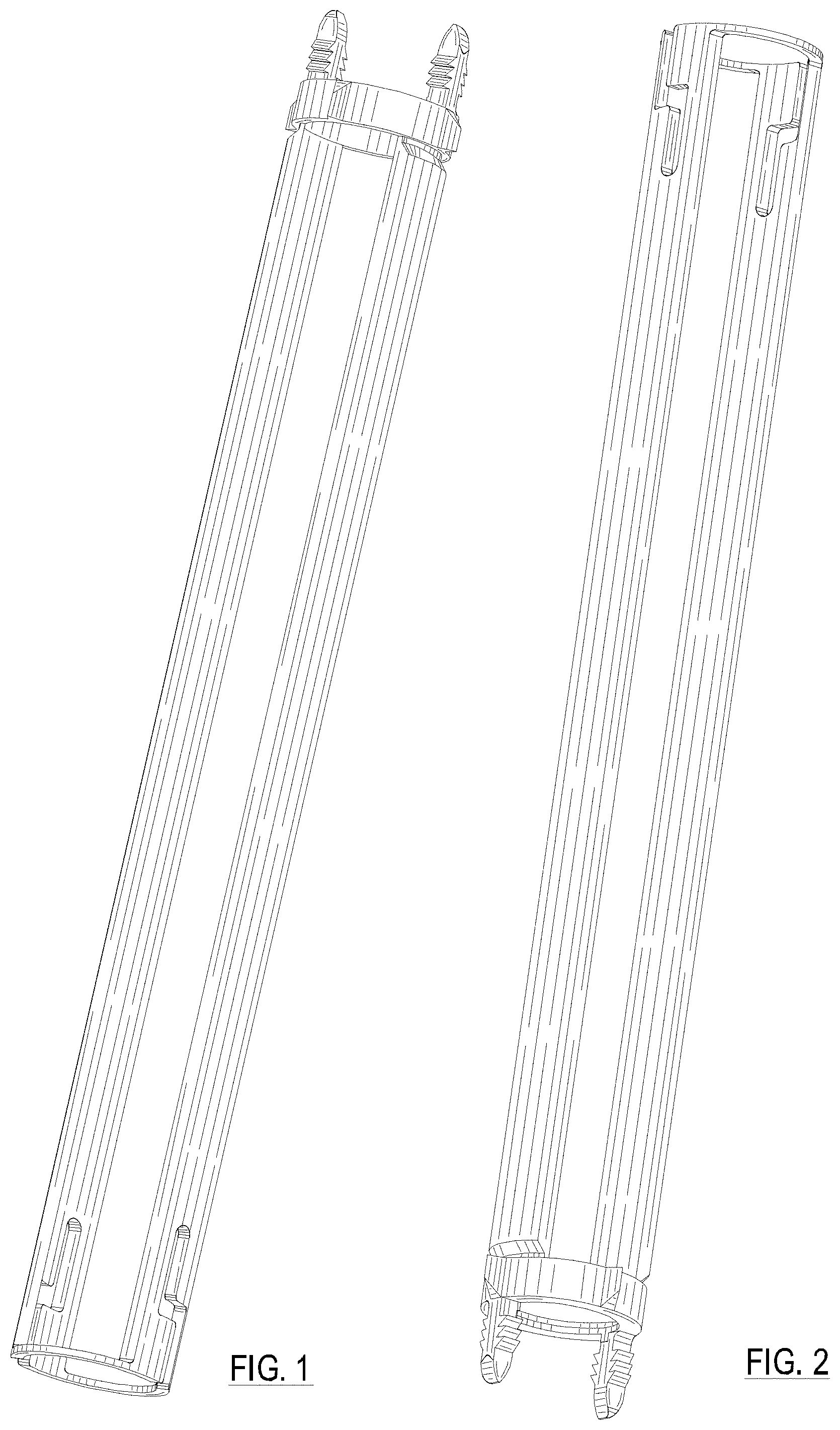
FIG. 1 is a perspective view of the surgical tool with the distal end of the surgical tool positioned in an upward position;
FIG. 2 is a perspective top view of the surgical tool of FIG. 1 with the proximal end of the surgical tool positioned in an upward position;
FIG. 3 is a side view of a first side of the surgical tool of FIG. 1;
FIG. 4 is a side view of a second side of the surgical tool of FIG. 1;
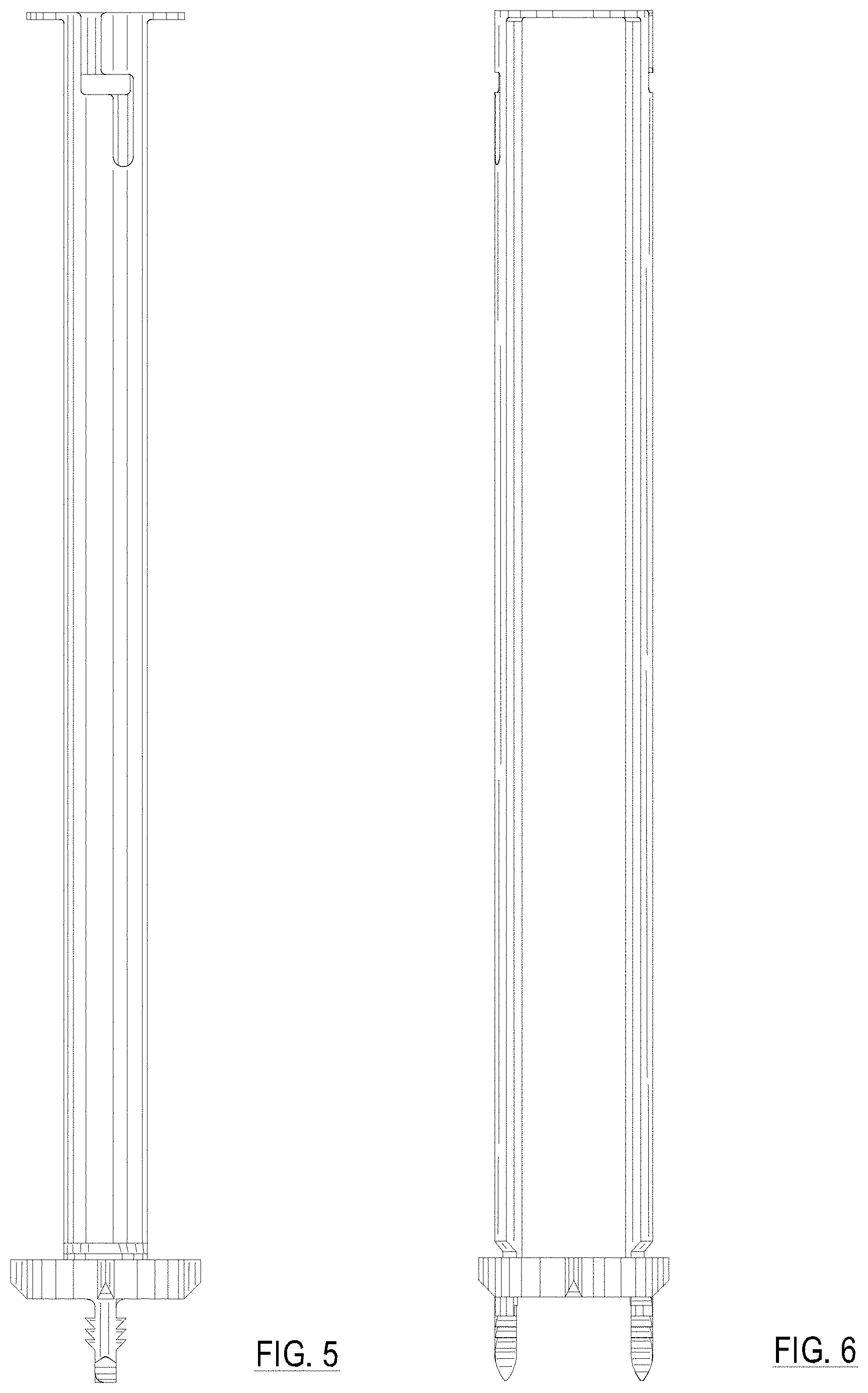
FIG. 5 is a side view of a third side of the surgical tool of FIG. 1;
FIG. 6 is a side view of a forth side of the surgical tool of FIG. 1;
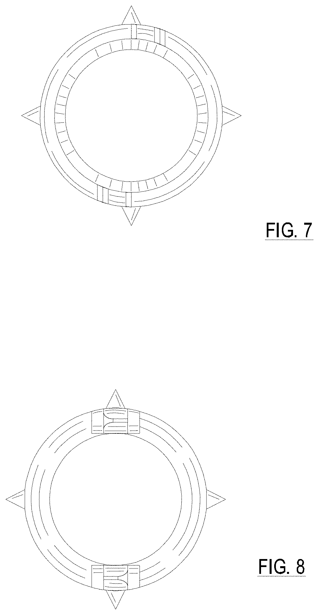
FIG. 7 is a view of the proximal end of the surgical tool of FIG. 1;
FIG. 8 is a view of the distal end of the surgical tool of FIG. 1;
FIG. 9 is a perspective view of a first alternative embodiment of the surgical tool with the distal end of the surgical tool positioned in an upward position;
FIG. 10 is a perspective top view of the surgical tool of FIG. 9 with the proximal end of the surgical tool positioned in an upward position;
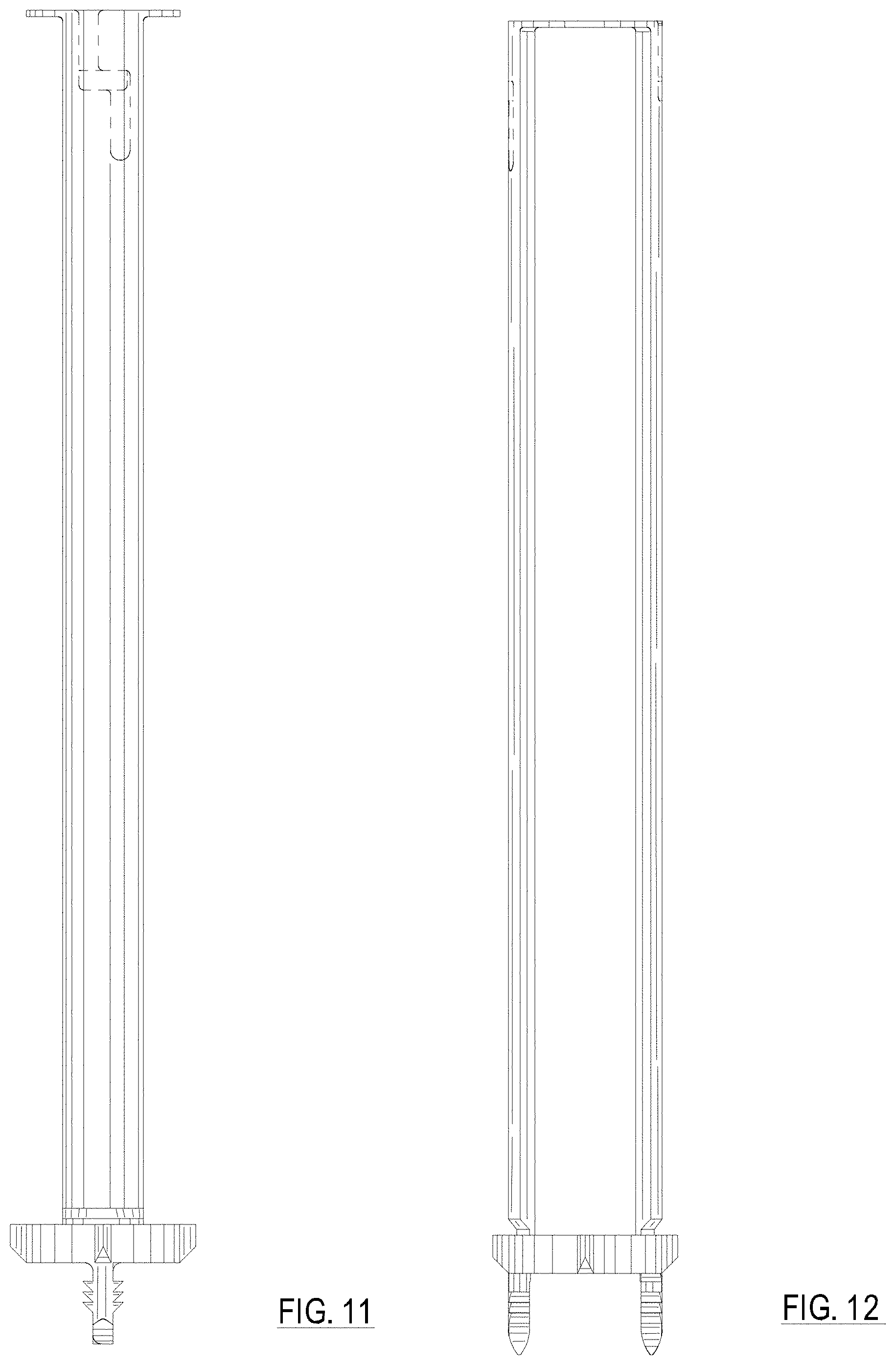
FIG. 11 is a side view of a first side of the surgical tool of FIG. 9;
FIG. 12 is a side view of a second side of the surgical tool of FIG. 9;
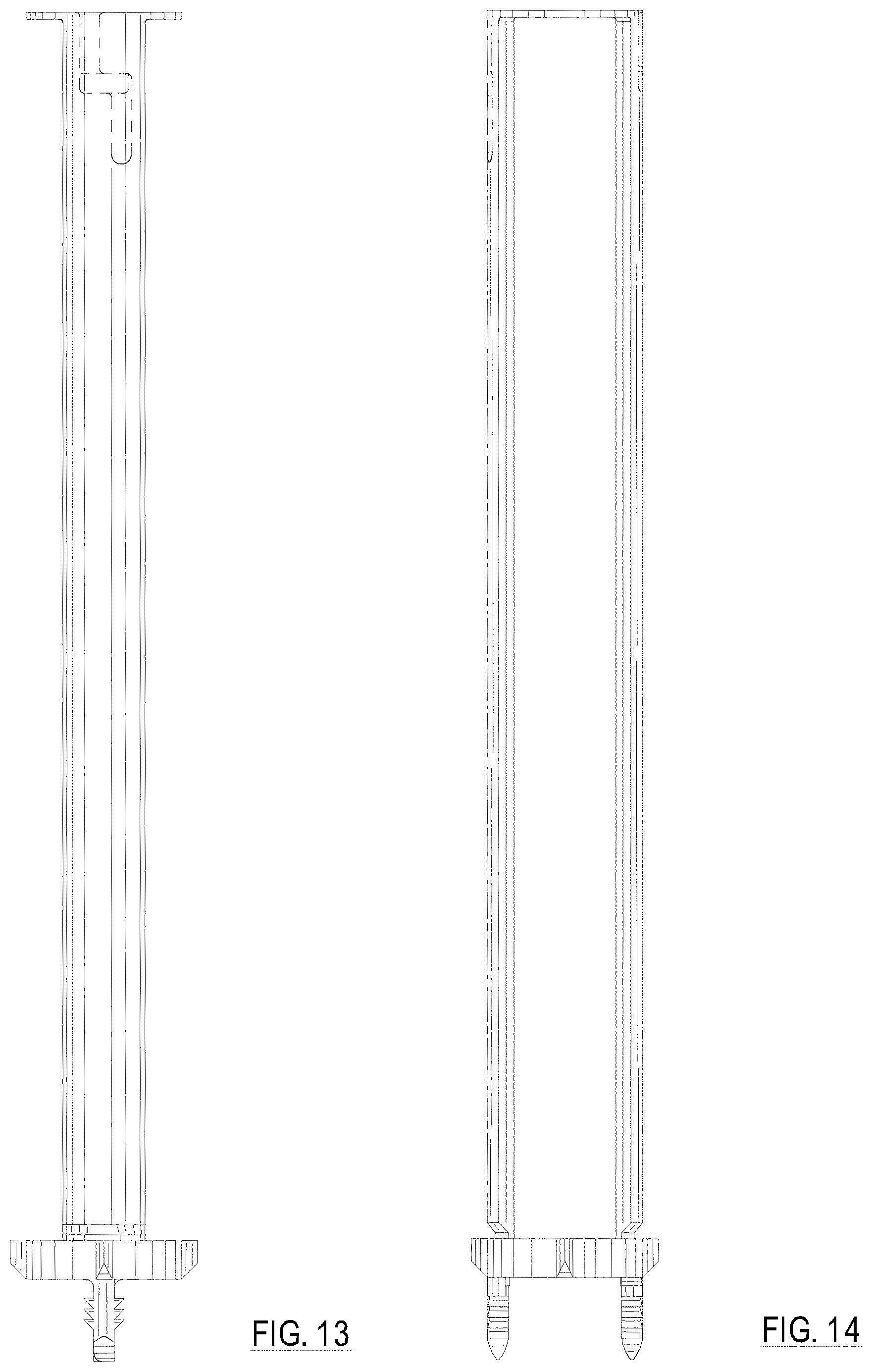
FIG. 13 is a side view of a third side of the surgical tool of FIG. 9;
FIG. 14 is a side view of a forth side of the surgical tool of FIG. 9;
FIG. 15 is a view of the proximal end of the surgical tool of FIG. 9;
FIG. 16 is a view of the distal end of the surgical tool of FIG. 9;
FIG. 17 is a perspective view of a second alternative embodiment of the surgical tool with the distal end of the surgical tool positioned in an upward position;
FIG. 18 is a perspective top view of the surgical tool of FIG. 17 with the proximal end of the surgical tool positioned in an upward position;
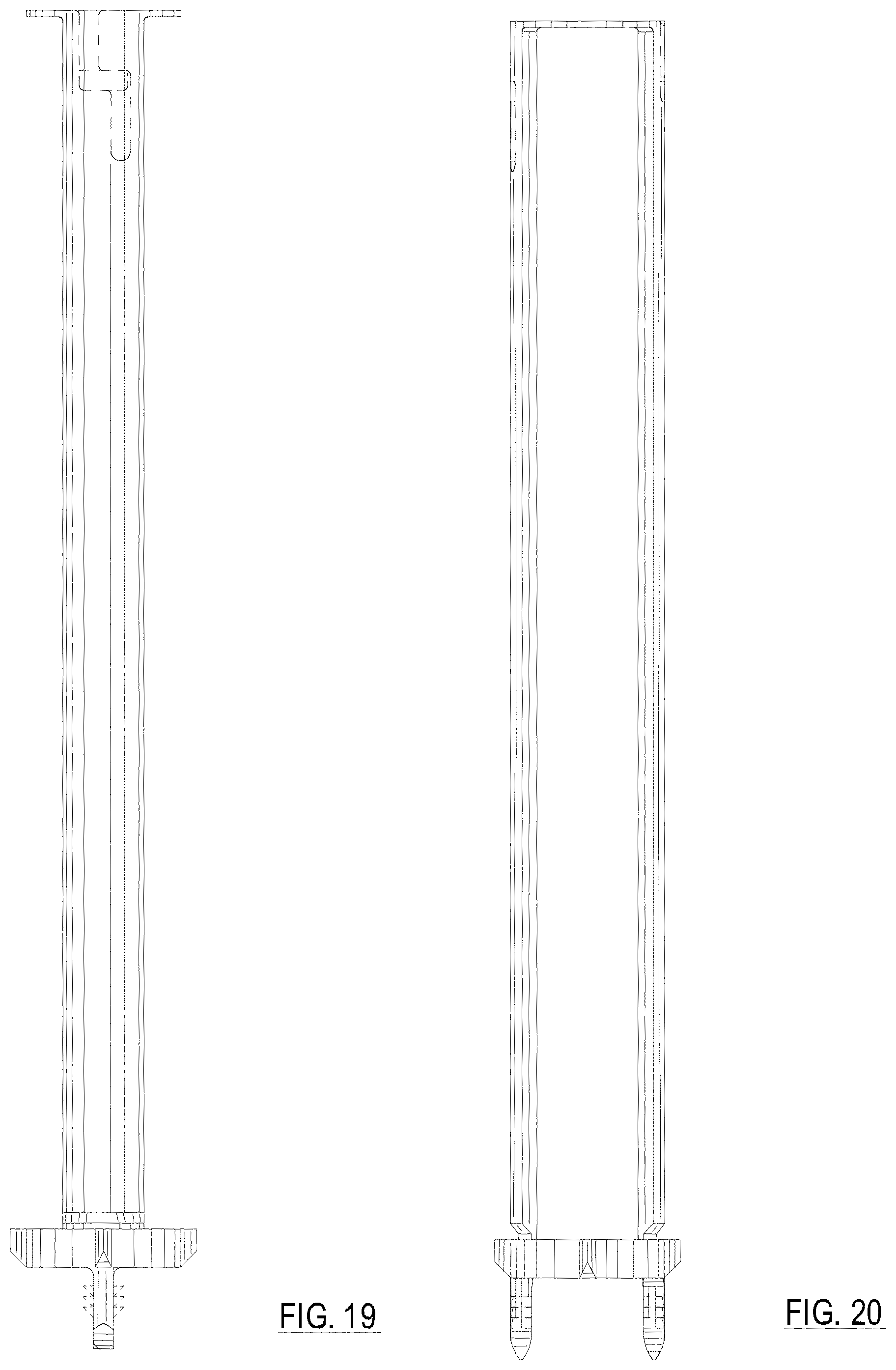
FIG. 19 is a side view of a first side of the surgical tool of FIG. 17;
FIG. 20 is a side view of a second side of the surgical tool of FIG. 17;
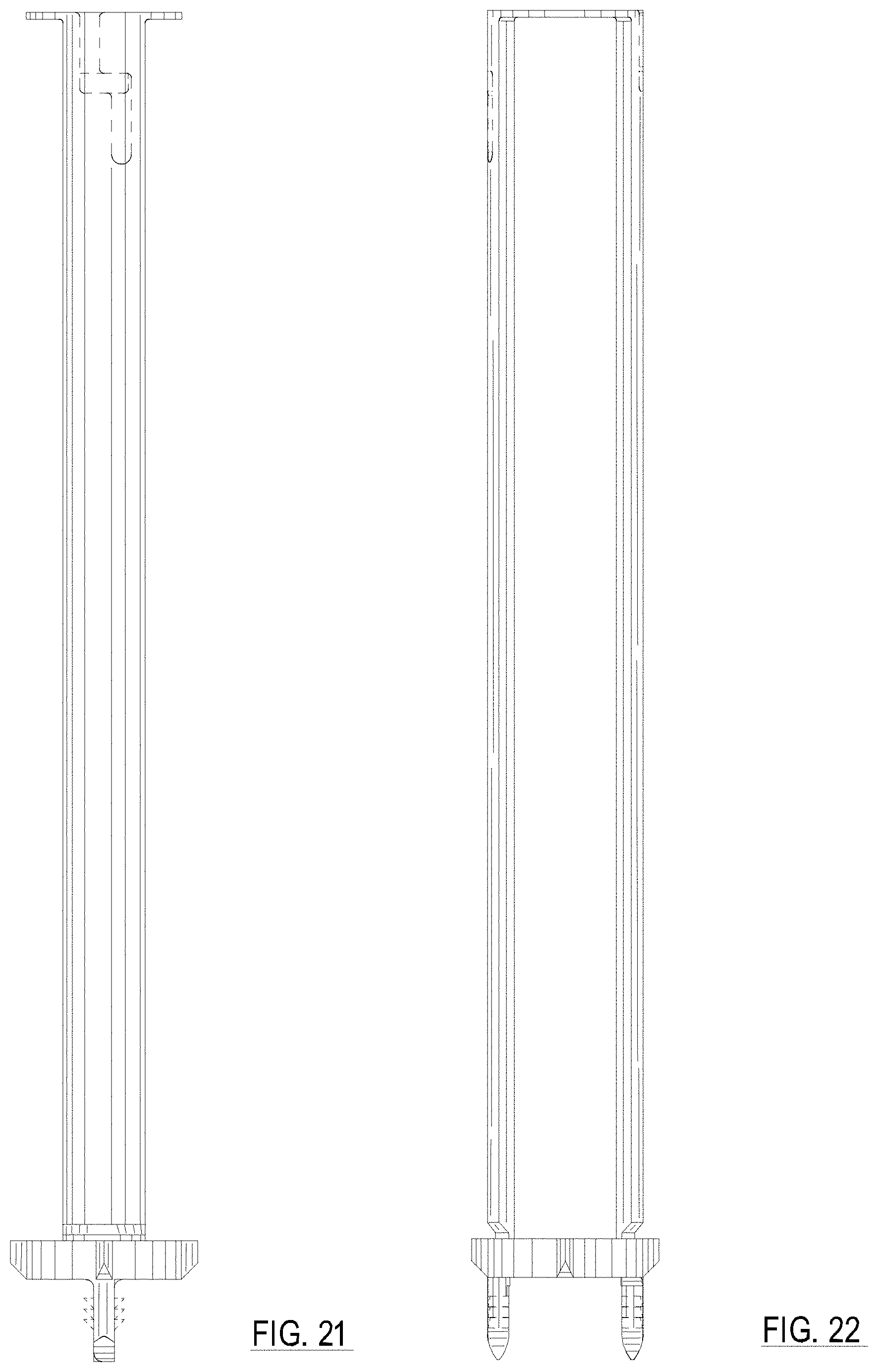
FIG. 21 is a side view of a third side of the surgical tool of FIG. 17;
FIG. 22 is a side view of a forth side of the surgical tool of FIG. 17;
FIG. 23 is a view of the proximal end of the surgical tool of FIG. 17; and
FIG. 24 is a view of the distal end of the surgical tool of FIG. 17.
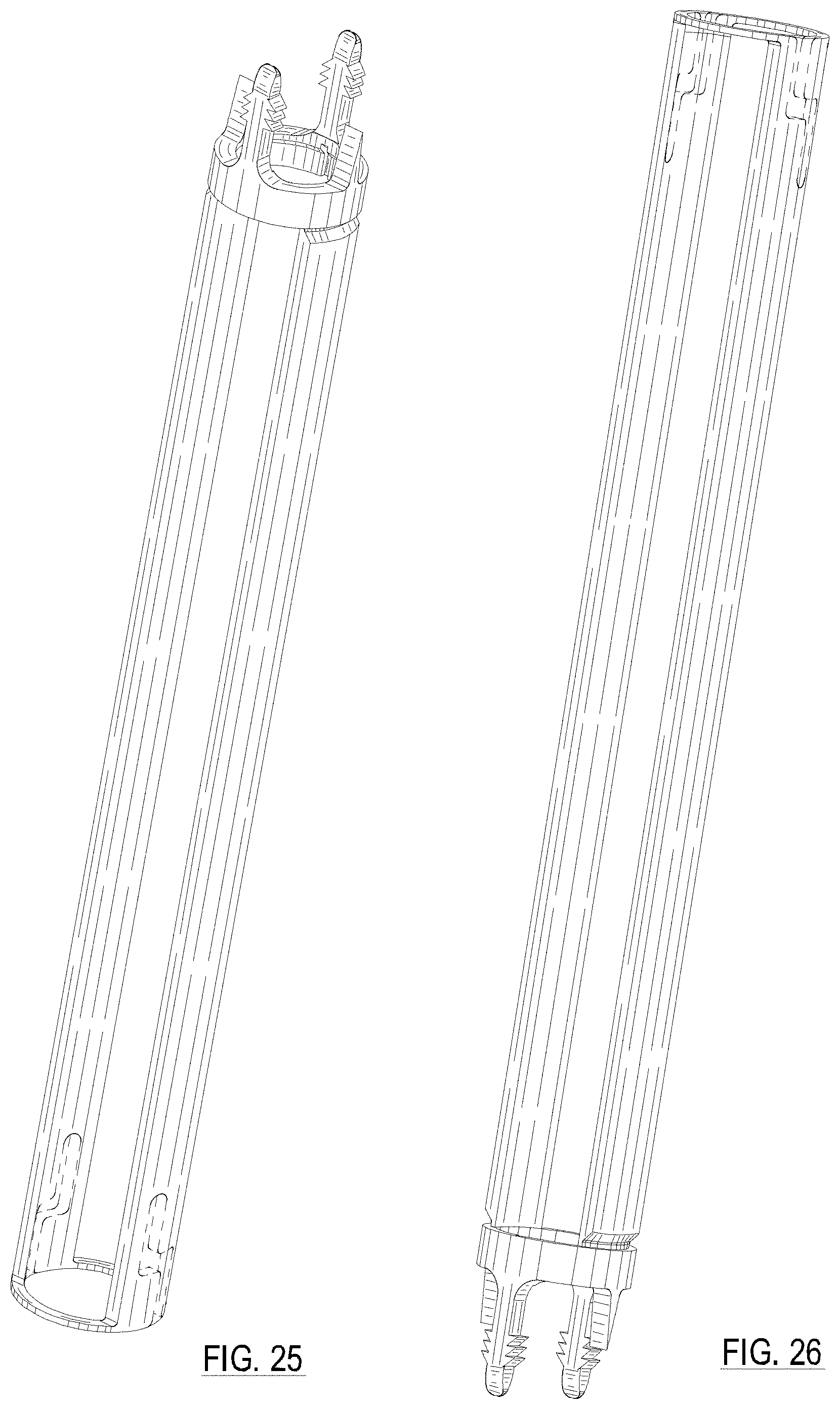
FIG. 25 is a perspective view of a third alternative embodiment of the surgical tool with the distal end of the surgical tool positioned in an upward position;
FIG. 26 is a perspective top view of the surgical tool of FIG. 25 with the proximal end of the surgical tool positioned in an upward position;
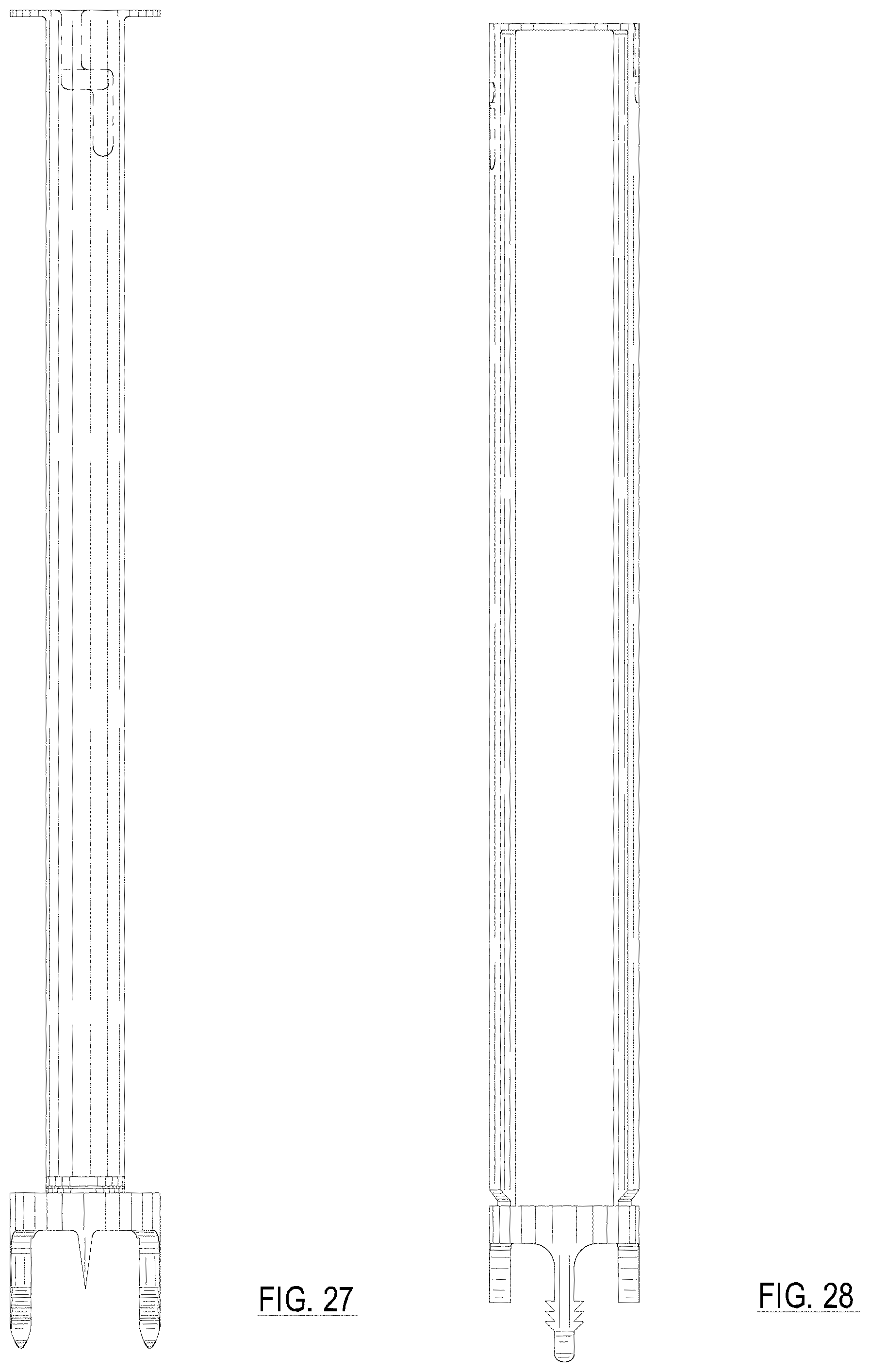
FIG. 27 is a side view of a first side of the surgical tool of FIG. 25;
FIG. 28 is a side view of a second side of the surgical tool of FIG. 25;
FIG. 29 is a side view of a third side of the surgical tool of FIG. 25;
FIG. 30 is a side view of a forth side of the surgical tool of FIG. 25;
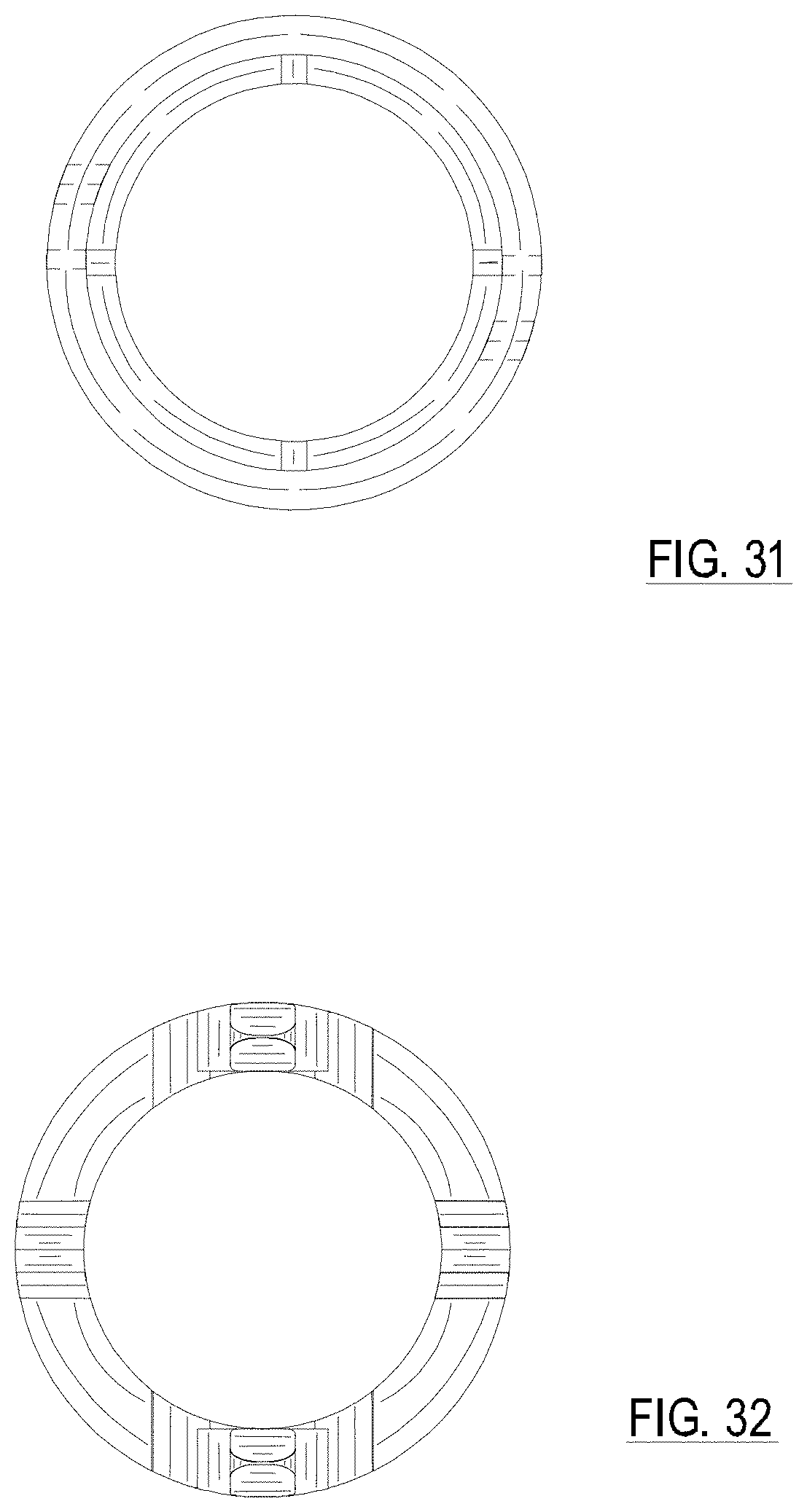
FIG. 31 is a view of the proximal end of the surgical tool of FIG. 25; and
FIG. 32 is a view of the distal end of the surgical tool of FIG. 25.
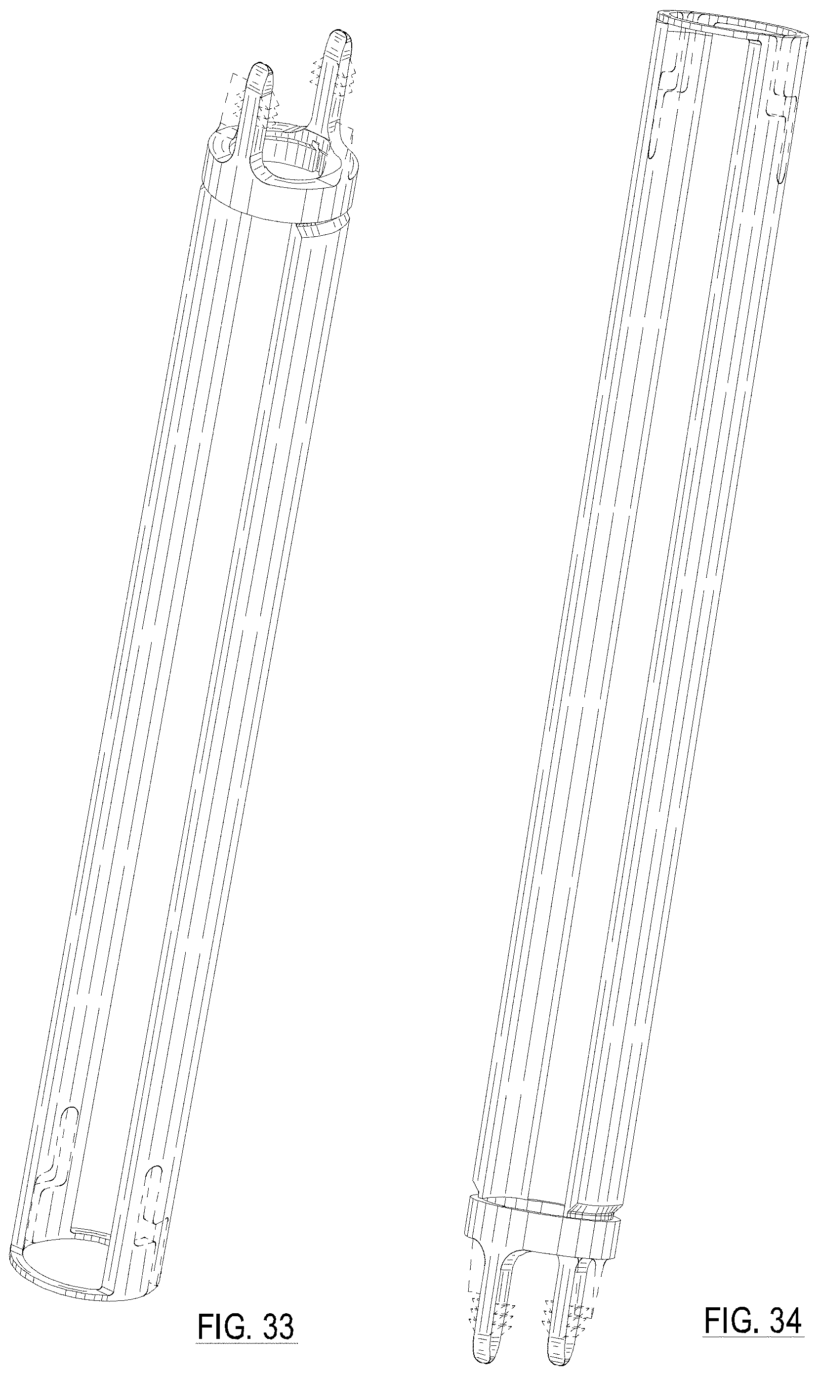
FIG. 33 is a perspective view of a fourth alternative embodiment of the surgical tool with the distal end of the surgical tool positioned in an upward position;
FIG. 34 is a perspective top view of the surgical tool of FIG. 33 with the proximal end of the surgical tool positioned in an upward position;
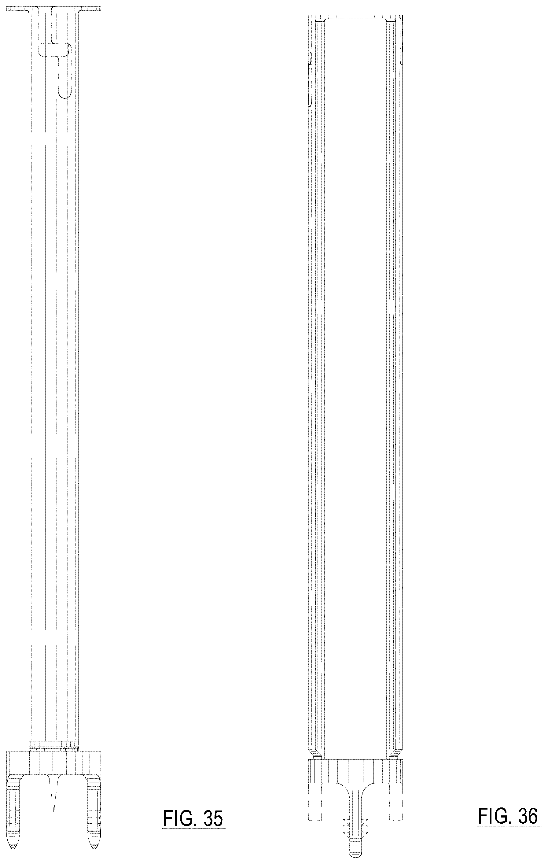
FIG. 35 is a side view of a first side of the surgical tool of FIG. 33;
FIG. 36 is a side view of a second side of the surgical tool of FIG. 33;
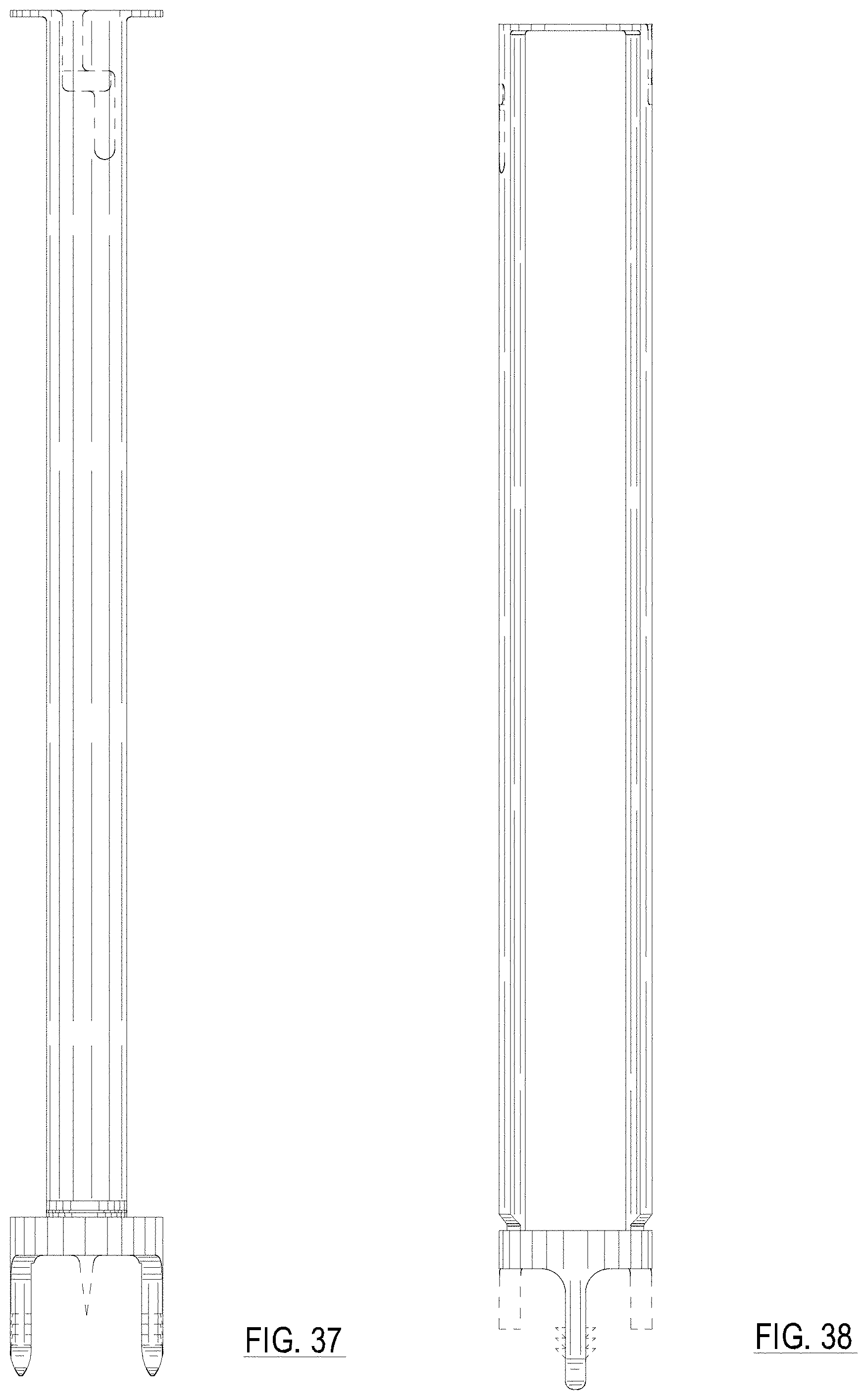
FIG. 37 is a side view of a third side of the surgical tool of FIG. 33;
FIG. 38 is a side view of a forth side of the surgical tool of FIG. 33;
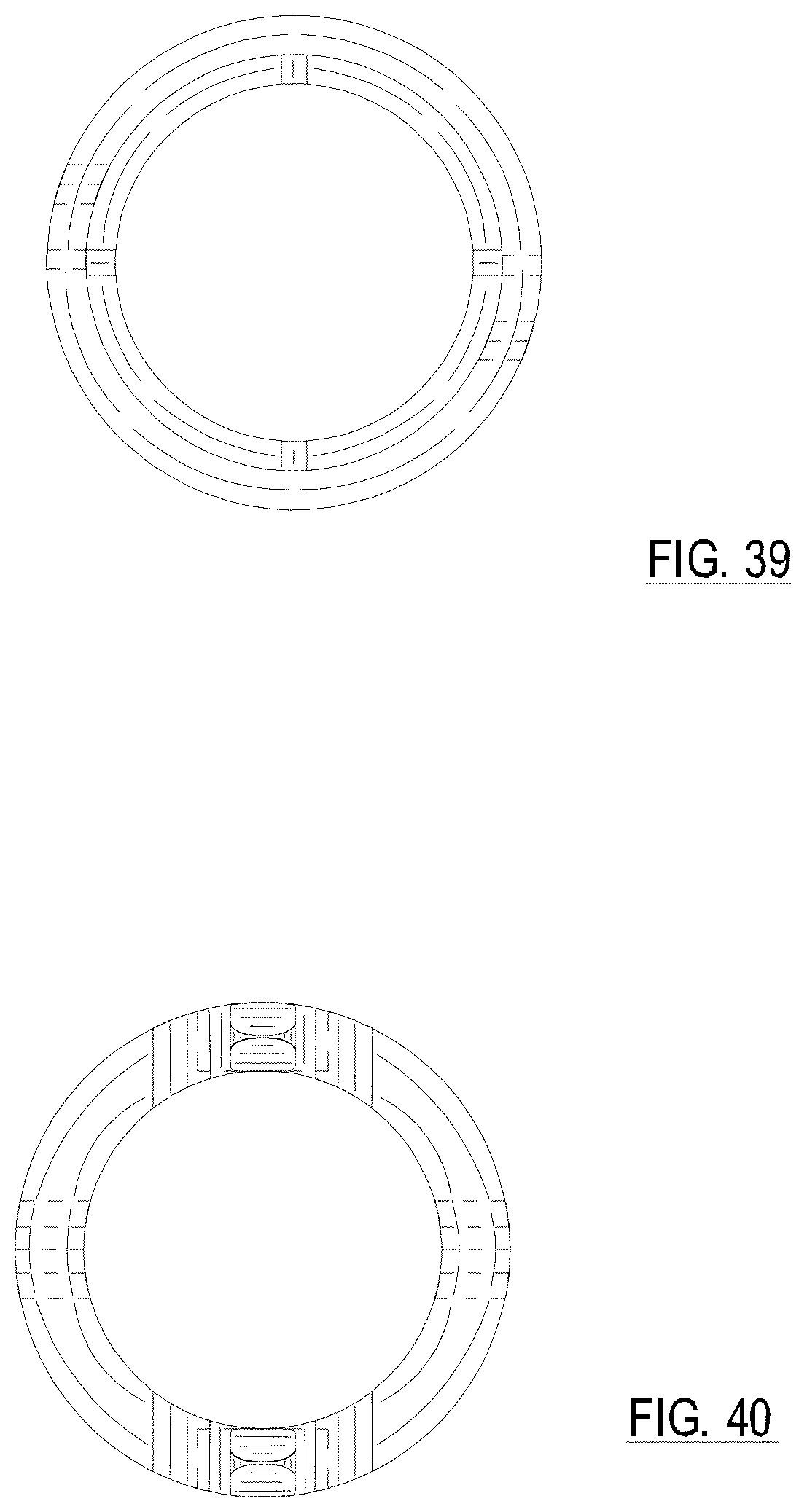
FIG. 39 is a view of the proximal end of the surgical tool of FIG. 33; and,
FIG. 40 is a view of the distal end of the surgical tool of FIG. 33.
The broken lines in the drawings illustrate portions of the surgical tool which form no part of the claimed design.
* * * * *
References
D00000
D00001
D00002
D00003
D00004
D00005
D00006
D00007
D00008
D00009
D00010
D00011
D00012

D00013
D00014
D00015

D00016
D00017
D00018
D00019
D00020
XML
uspto.report is an independent third-party trademark research tool that is not affiliated, endorsed, or sponsored by the United States Patent and Trademark Office (USPTO) or any other governmental organization. The information provided by uspto.report is based on publicly available data at the time of writing and is intended for informational purposes only.
While we strive to provide accurate and up-to-date information, we do not guarantee the accuracy, completeness, reliability, or suitability of the information displayed on this site. The use of this site is at your own risk. Any reliance you place on such information is therefore strictly at your own risk.
All official trademark data, including owner information, should be verified by visiting the official USPTO website at www.uspto.gov. This site is not intended to replace professional legal advice and should not be used as a substitute for consulting with a legal professional who is knowledgeable about trademark law.