Drawer part
Irgang , et al. May 11, 2
U.S. patent number D918,632 [Application Number D/739,171] was granted by the patent office on 2021-05-11 for drawer part. This patent grant is currently assigned to Julius Blum GmbH. The grantee listed for this patent is Julius Blum GmbH. Invention is credited to Markus Irgang, Elvis Music, Emanuel Netzer, Guenter Schwarzmann.


| United States Patent | D918,632 |
| Irgang , et al. | May 11, 2021 |
Drawer part
Claims
CLAIM The ornamental design for a drawer part, as shown and described.
| Inventors: | Irgang; Markus (Altach, AT), Schwarzmann; Guenter (Dornbirn, AT), Netzer; Emanuel (Hoechst, AT), Music; Elvis (Lindau, DE) | ||||||||||
|---|---|---|---|---|---|---|---|---|---|---|---|
| Applicant: |
|
||||||||||
| Assignee: | Julius Blum GmbH (Hoechst,
AT) |
||||||||||
| Appl. No.: | D/739,171 | ||||||||||
| Filed: | June 23, 2020 |
Related U.S. Patent Documents
| Application Number | Filing Date | Patent Number | Issue Date | ||
|---|---|---|---|---|---|
| 29654000 | Jun 20, 2018 | ||||
Foreign Application Priority Data
| Dec 22, 2017 [EM] | 4562304-0017 | |||
| Current U.S. Class: | D6/705 |
| Current International Class: | 0606 |
| Field of Search: | ;D6/703,703.2,703.3,705,705.2,705.4,705.5,705.7,707.19,707.25,706 |
References Cited [Referenced By]
U.S. Patent Documents
| D326381 | May 1992 | Heiligenthal |
| D563125 | March 2008 | Held |
| D572511 | July 2008 | Bohler |
| D577936 | October 2008 | Held |
| D686429 | July 2013 | Kampl |
| D840182 | February 2019 | Warden |
| 2020/0000226 | January 2020 | Kampl |
| WO-2016131603 | Aug 2016 | WO | |||
Attorney, Agent or Firm: Wenderoth, Lind & Ponack, L.L.P.
Description
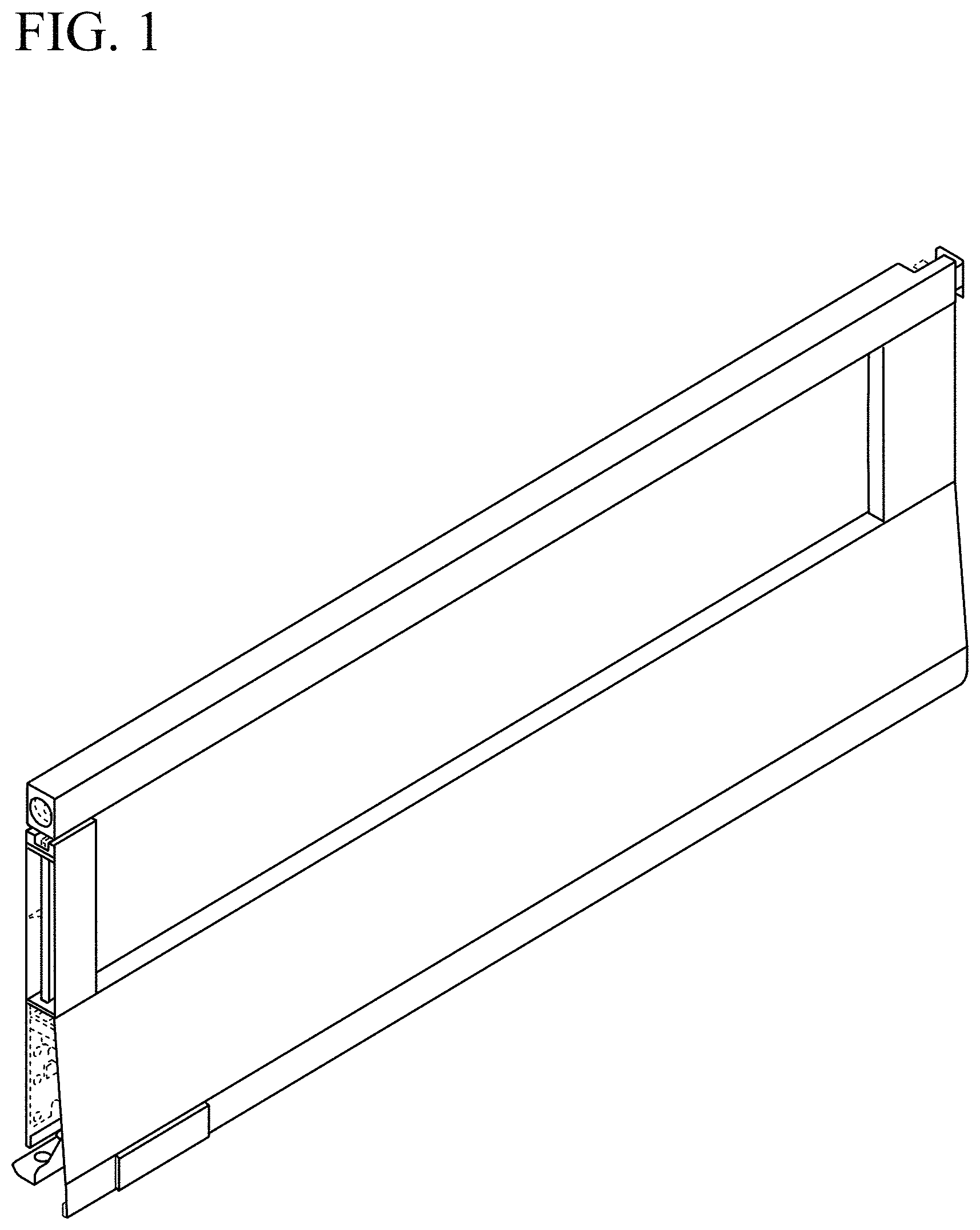
FIG. 1 is a front perspective view of a drawer part;
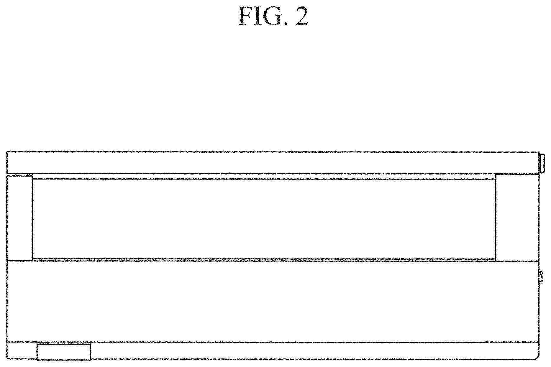
FIG. 2 is a front view thereof;
FIG. 3 is a left side view thereof;
FIG. 4 is a right side view thereof;
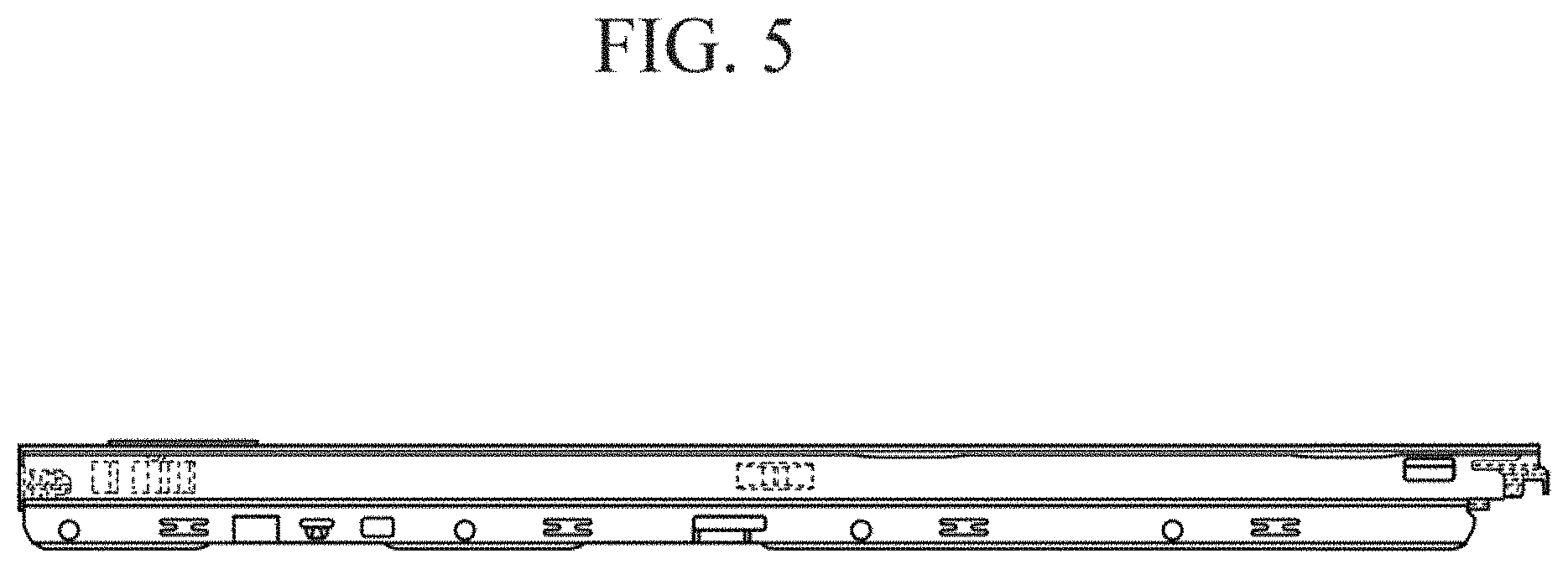
FIG. 5 is a bottom view thereof;
FIG. 6 is a top view thereof;
FIG. 7 is a rear view thereof; and,
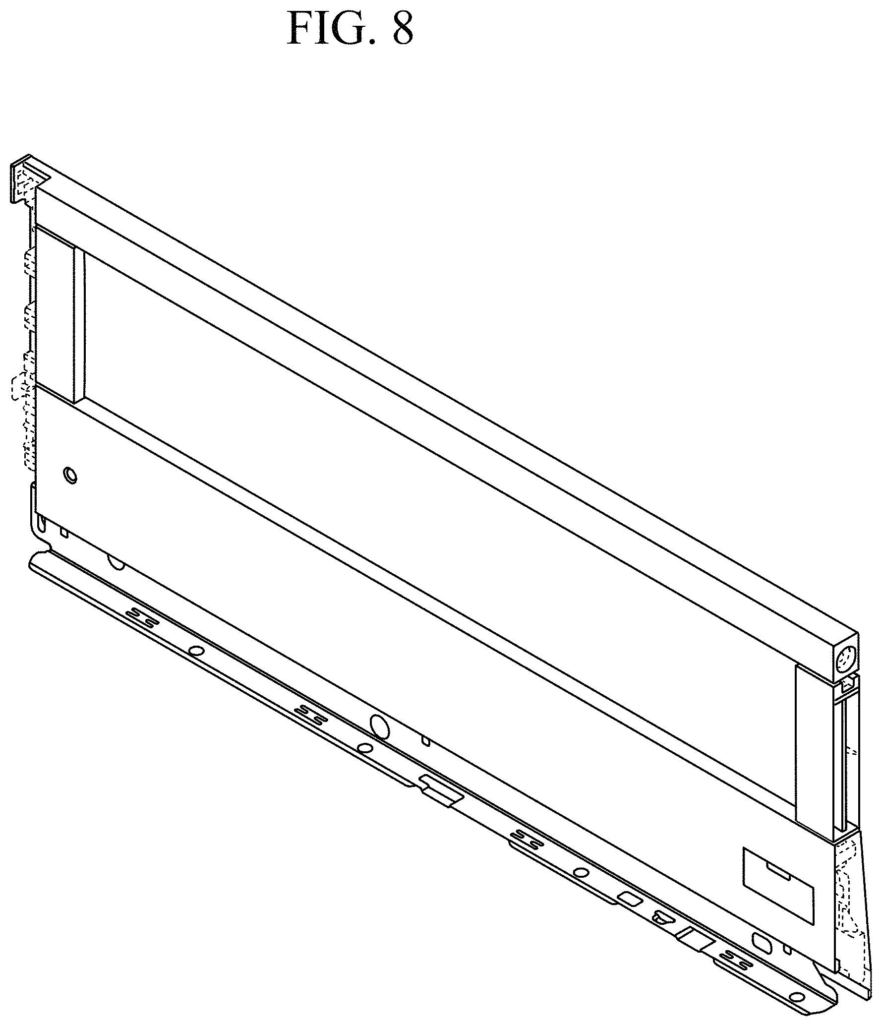
FIG. 8 is a rear perspective view thereof.
The broken lines shown herein are for illustrative purposes only and form no part of the claimed design.
* * * * *
D00000
D00001
D00002
D00003
D00004
D00005
D00006
D00007
D00008
XML
uspto.report is an independent third-party trademark research tool that is not affiliated, endorsed, or sponsored by the United States Patent and Trademark Office (USPTO) or any other governmental organization. The information provided by uspto.report is based on publicly available data at the time of writing and is intended for informational purposes only.
While we strive to provide accurate and up-to-date information, we do not guarantee the accuracy, completeness, reliability, or suitability of the information displayed on this site. The use of this site is at your own risk. Any reliance you place on such information is therefore strictly at your own risk.
All official trademark data, including owner information, should be verified by visiting the official USPTO website at www.uspto.gov. This site is not intended to replace professional legal advice and should not be used as a substitute for consulting with a legal professional who is knowledgeable about trademark law.