Cashing machine
Luo , et al. April 27, 2
U.S. patent number D917,611 [Application Number D/693,810] was granted by the patent office on 2021-04-27 for cashing machine. This patent grant is currently assigned to PAX COMPUTER TECHNOLOGY (SHENZHEN) CO., LTD.. The grantee listed for this patent is PAX COMPUTER TECHNOLOGY (SHENZHEN) CO., LTD.. Invention is credited to Yan Chen, Haibin Guo, Shaowen Luo.


View All Diagrams
| United States Patent | D917,611 |
| Luo , et al. | April 27, 2021 |
Cashing machine
Claims
CLAIM The ornamental design for a cashing machine, as shown and described.
| Inventors: | Luo; Shaowen (Shenzhen, CN), Chen; Yan (Shenzhen, CN), Guo; Haibin (Shenzhen, CN) | ||||||||||
|---|---|---|---|---|---|---|---|---|---|---|---|
| Applicant: |
|
||||||||||
| Assignee: | PAX COMPUTER TECHNOLOGY (SHENZHEN)
CO., LTD. (Shenzhen, CN) |
||||||||||
| Appl. No.: | D/693,810 | ||||||||||
| Filed: | June 5, 2019 |
Foreign Application Priority Data
| Dec 29, 2018 [CN] | 201830770400.X | |||
| Current U.S. Class: | D18/4.6; D14/385 |
| Current International Class: | 1801 |
| Field of Search: | ;D18/4.4,4.5,4.6,2,11,50,14,19-21,54,54.1,99,4.1,4.3,3.1 ;D10/46,61,62,70,104.1,104.2,106.2,106.6,65,66 ;D20/1,8,9 ;D14/496,299,338,339,341,346,383,385,386,387,440,507,137,138R,138AA,138G ;D99/28,43 |
References Cited [Referenced By]
U.S. Patent Documents
| D289291 | April 1987 | Kapper |
| D308858 | June 1990 | Tarver |
| D308859 | June 1990 | Tarver |
| D321172 | October 1991 | Moore, IV |
| D338452 | August 1993 | Allgeier |
| D346591 | May 1994 | Lee |
| D354276 | January 1995 | Wilson |
| D367647 | March 1996 | Faggard |
| D379825 | June 1997 | Droege |
| D381675 | July 1997 | Droege |
| D393479 | April 1998 | Droege |
| D410441 | June 1999 | Lin |
| D424602 | May 2000 | Lin |
| D428019 | July 2000 | Amron |
| D430379 | August 2000 | Massey |
| D447136 | August 2001 | Groves |
| D503172 | March 2005 | Izumi |
| D515092 | February 2006 | Wilfong |
| D528146 | September 2006 | Fitch |
| D542791 | May 2007 | Fitch |
| D590575 | April 2009 | Bleck |
| D618355 | June 2010 | Delaey |
| D620519 | July 2010 | Branck |
| D626550 | November 2010 | Julien |
| D681036 | April 2013 | Taunay da Graca Couto |
| D690349 | September 2013 | Qin |
| D697062 | January 2014 | Nagai |
| D701779 | April 2014 | Bremenkamp |
| D706863 | June 2014 | Branck |
| D759748 | June 2016 | Beatty |
| D762766 | August 2016 | Bedier |
| 9482382 | November 2016 | Olsen |
| D791860 | July 2017 | Greaves |
| D798378 | September 2017 | Kim |
| D810817 | February 2018 | Wang |
| D813863 | March 2018 | Barea |
| D814559 | April 2018 | Oross |
| D818524 | May 2018 | Dong |
| D823935 | July 2018 | Wang |
| D829274 | September 2018 | Huang |
| D829704 | October 2018 | Oross |
| D831106 | October 2018 | Saeed |
| D842149 | March 2019 | Haag |
| D842296 | March 2019 | Oross |
| D851169 | June 2019 | Yaginuma |
| D857791 | August 2019 | Luo |
| D859516 | September 2019 | Wang |
| D861685 | October 2019 | Wang |
| D872171 | January 2020 | Luo |
| D880580 | April 2020 | Wang |
| D881269 | April 2020 | Blanc |
| D886190 | June 2020 | Huang |
| D907696 | January 2021 | Chau |
| D909469 | February 2021 | Watanabe |
| 2003/0132294 | July 2003 | Gomez |
| 2006/0181515 | August 2006 | Fletcher |
| 2018/0374070 | December 2018 | Bedier |
| 2019/0005476 | January 2019 | Luo |
| 2020/0111074 | April 2020 | Chau |
Other References
|
POS Payment Terminals. (Design--.COPYRGT. Questel) orbit.com. [online PDF] 47 pgs. Print Dates Range Jun. 29, 2015-Aug. 30, 2019 [Retrieved Dec. 4, 2020] https://www.orbit.com/export/QPTUJ214/pdf2/a1a1ed44-08fc-44c8-be48-- 51f1ff9aa5a6-184510.pdf. cited by examiner. |
Primary Examiner: Fast Horse; Marie D.
Attorney, Agent or Firm: Rankin, Hill & Clark LLP
Description
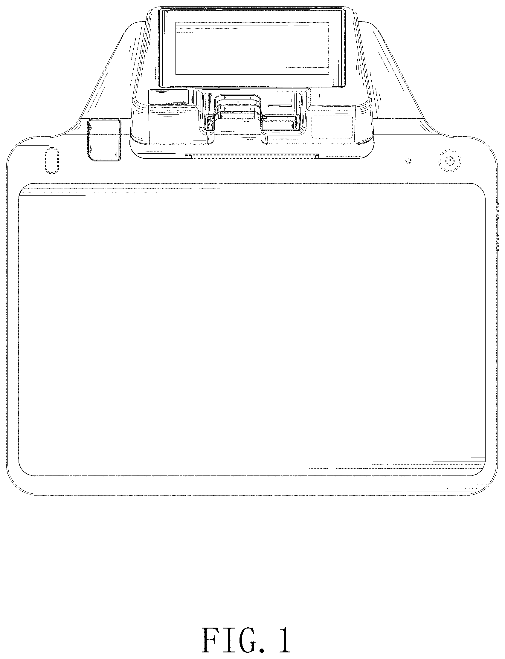
FIG. 1 is a front view of a cashing machine according to our new design;
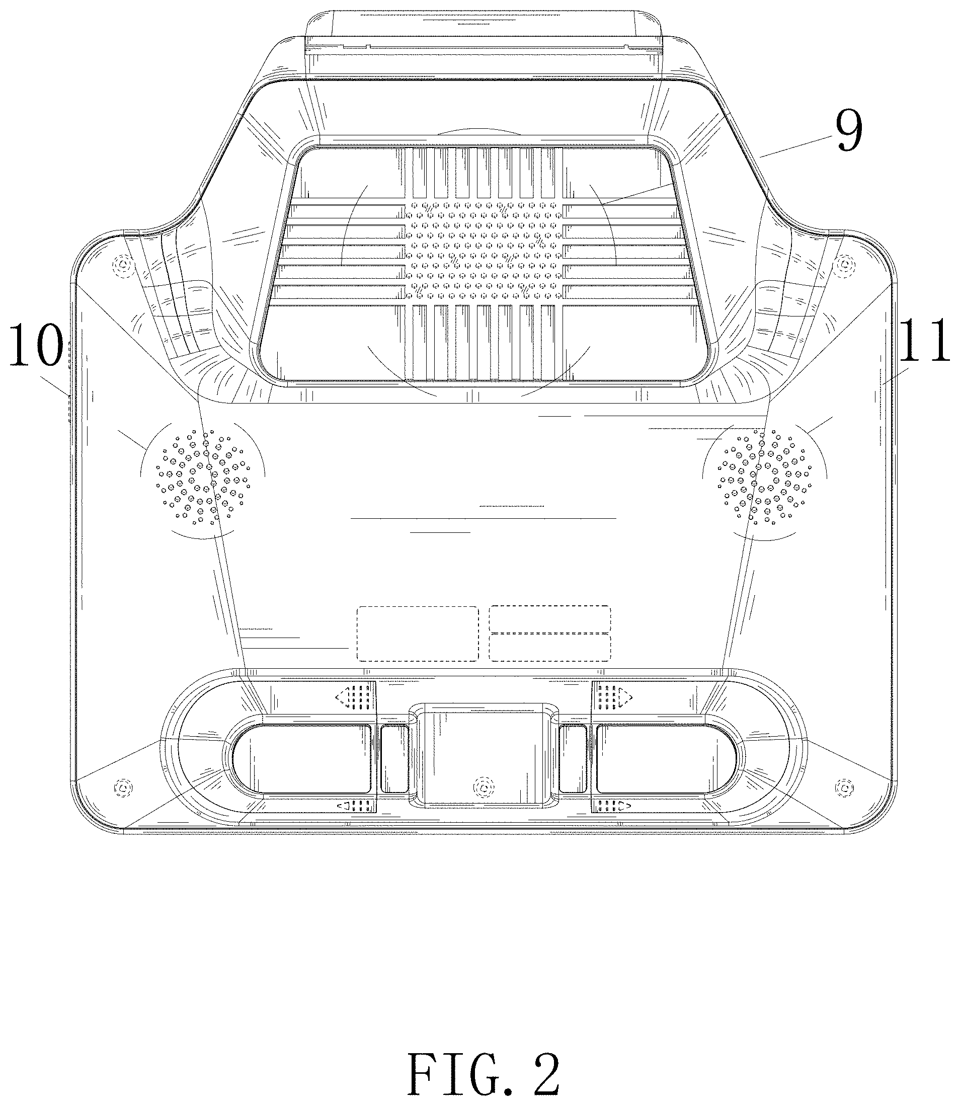
FIG. 2 is a rear view of the cashing machine;
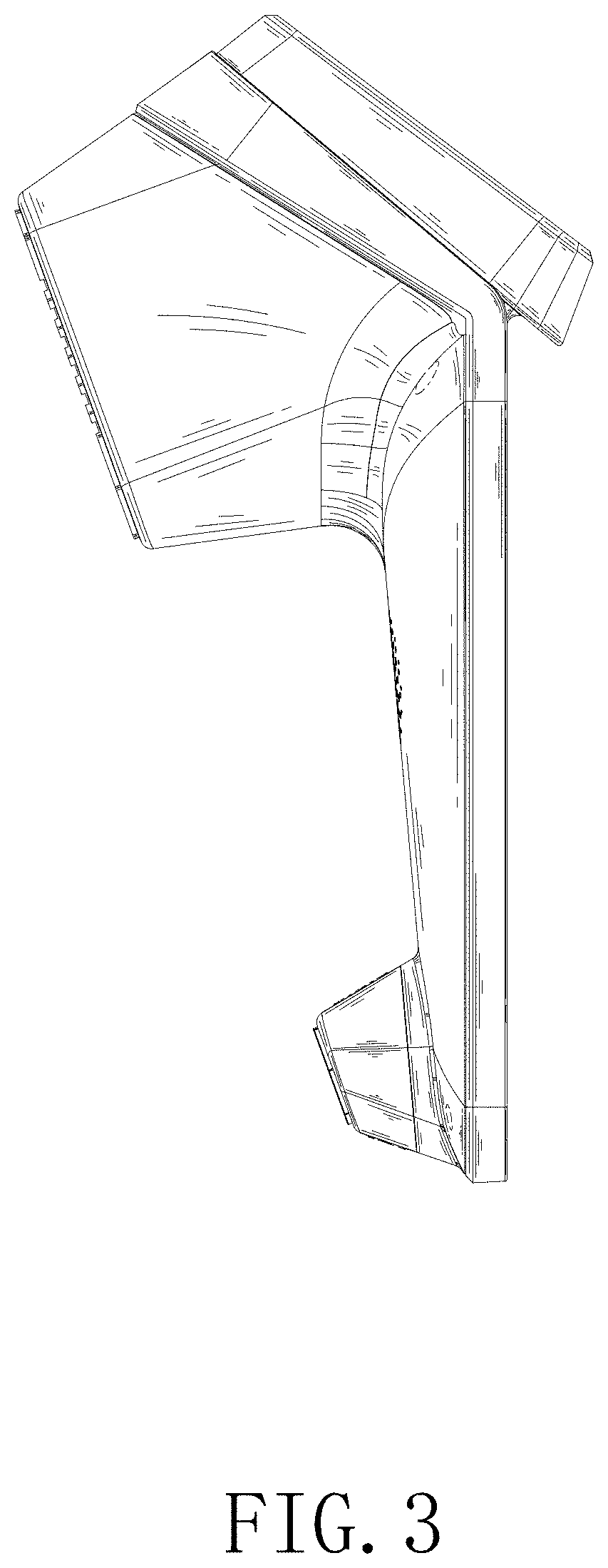
FIG. 3 is a left side view of the cashing machine;
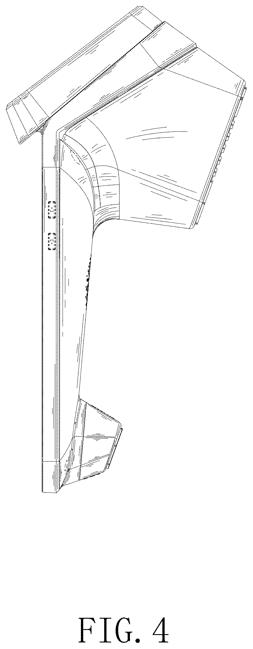
FIG. 4 is a right side view of the cashing machine;
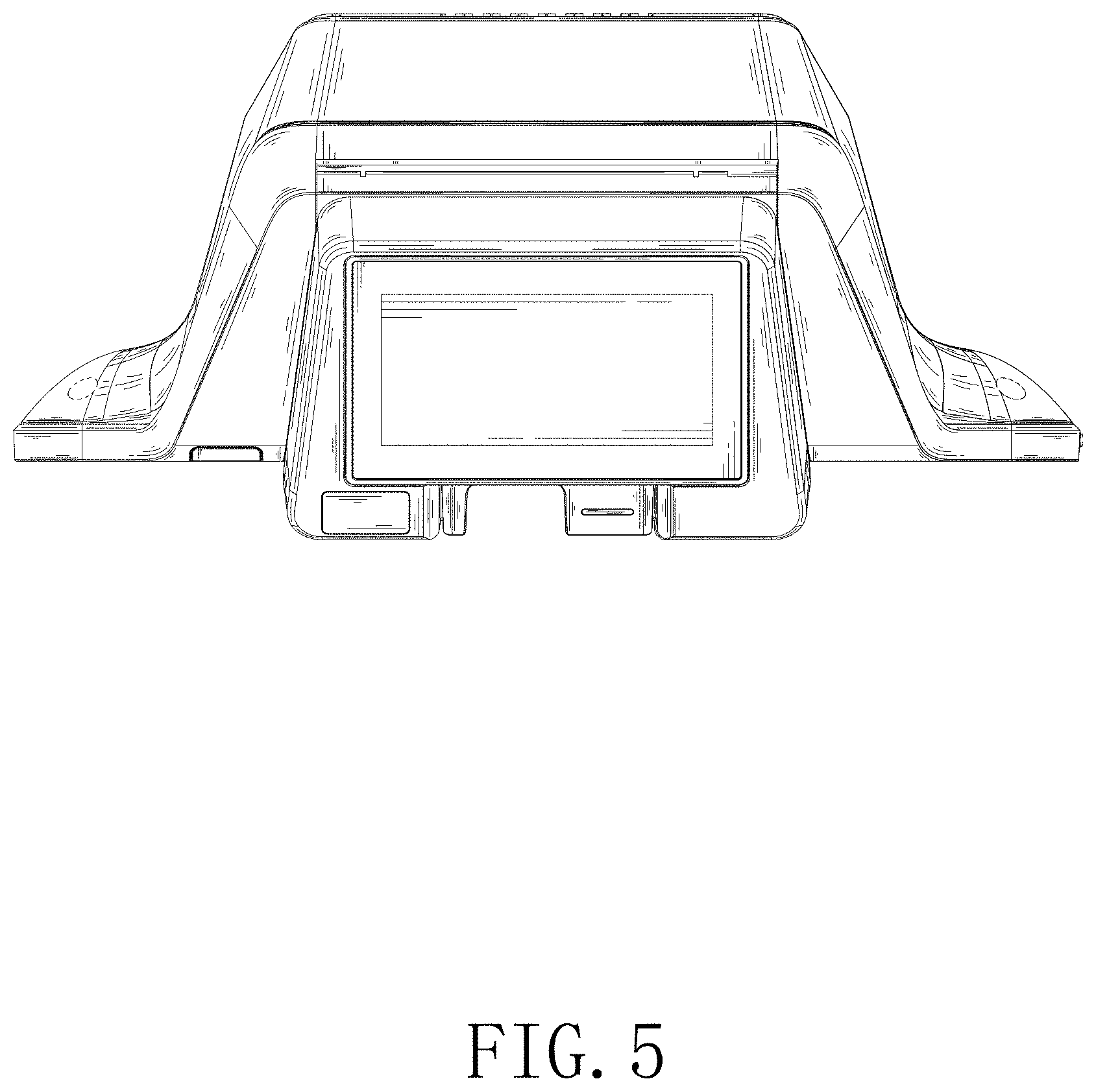
FIG. 5 is a top view of the cashing machine;
FIG. 6 is a bottom view of the cashing machine;
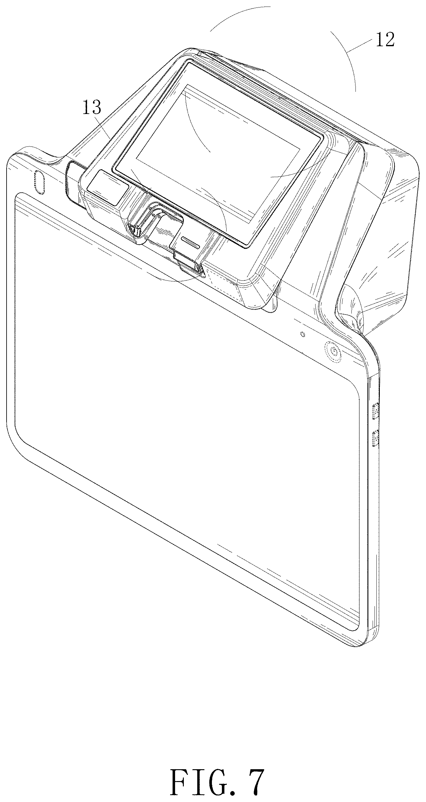
FIG. 7 is a first perspective view of the cashing machine;
FIG. 8 is a second perspective view of the cashing machine;
FIG. 9 is an enlarged detail view of area 9 in FIG. 2;
FIG. 10 is an enlarged detail view of area 10 in FIG. 2;
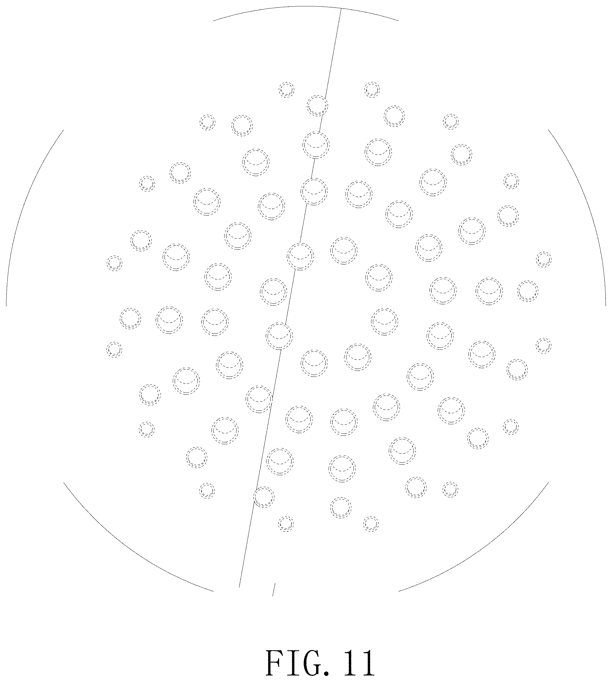
FIG. 11 is an enlarged detail view of area 11 in FIG. 2;
FIG. 12 is an enlarged detail view of area 12 in FIG. 7;
FIG. 13 is an enlarged detail view of area 13 in FIG. 7; and,
FIG. 14 is an enlarged detail view of area 14 in FIG. 8.
The broken lines in the drawings depict portions of the cashing machine that form no part of the claimed design. The broken lines consisting of long dashes depict reference to the enlargements shown in the figures and form no part of the claimed design.
* * * * *
References
D00000
D00001
D00002
D00003
D00004
D00005
D00006
D00007
D00008
D00009
D00010
D00011
D00012

D00013

D00014

XML
uspto.report is an independent third-party trademark research tool that is not affiliated, endorsed, or sponsored by the United States Patent and Trademark Office (USPTO) or any other governmental organization. The information provided by uspto.report is based on publicly available data at the time of writing and is intended for informational purposes only.
While we strive to provide accurate and up-to-date information, we do not guarantee the accuracy, completeness, reliability, or suitability of the information displayed on this site. The use of this site is at your own risk. Any reliance you place on such information is therefore strictly at your own risk.
All official trademark data, including owner information, should be verified by visiting the official USPTO website at www.uspto.gov. This site is not intended to replace professional legal advice and should not be used as a substitute for consulting with a legal professional who is knowledgeable about trademark law.