Adjustable groove masonry clamp
Green April 20, 2
U.S. patent number D916,703 [Application Number D/715,416] was granted by the patent office on 2021-04-20 for adjustable groove masonry clamp. The grantee listed for this patent is Andy Green. Invention is credited to Andy Green.


View All Diagrams
| United States Patent | D916,703 |
| Green | April 20, 2021 |
Adjustable groove masonry clamp
Claims
CLAIM The ornamental design for an adjustable groove masonry clamp, as shown and described.
| Inventors: | Green; Andy (Ozark, MO) | ||||||||||
|---|---|---|---|---|---|---|---|---|---|---|---|
| Applicant: |
|
||||||||||
| Appl. No.: | D/715,416 | ||||||||||
| Filed: | December 2, 2019 |
Related U.S. Patent Documents
| Application Number | Filing Date | Patent Number | Issue Date | ||
|---|---|---|---|---|---|
| 16579101 | Sep 23, 2019 | ||||
| Current U.S. Class: | D14/394 |
| Current International Class: | 0808 |
| Field of Search: | ;D16/242 ;D8/373,380,394-396,71-74 |
References Cited [Referenced By]
U.S. Patent Documents
| 2519652 | August 1950 | Hargrave |
| 2667678 | February 1954 | Hargrave et al. |
| 3247893 | April 1966 | Ford |
| D256661 | September 1980 | Graham |
| 4363459 | December 1982 | Holzer |
| 6402111 | June 2002 | Stewart |
| D484399 | December 2003 | Arthur |
| D491054 | June 2004 | Caterinacci, Jr. |
| D523736 | June 2006 | Lu |
| 7128354 | October 2006 | Wu |
| D551538 | September 2007 | Pearce |
| D616729 | June 2010 | Anderson |
| D657054 | April 2012 | Bacon |
| D667290 | September 2012 | Chelton |
| D678043 | March 2013 | Lu |
| D695173 | December 2013 | Sperry |
| D701260 | March 2014 | Burton |
| 8672307 | March 2014 | Pacheco et al. |
| D727716 | April 2015 | Langle |
| 9307700 | April 2016 | Schmitt |
| D808576 | January 2018 | Clarke |
| D815184 | April 2018 | Gu |
| D838308 | January 2019 | Swan |
| D876210 | February 2020 | Arnall |
| D878184 | March 2020 | Holloway |
| 2003/0155683 | August 2003 | Pietrobon |
| 2008/0283702 | November 2008 | Ikerd |
Attorney, Agent or Firm: Keisling & Pieper PLC Pieper; David B. Keisling; Trent C.
Description
FIG. 1 is a perspective view of an adjustable groove masonry clamp showing my new design in an expanded position;
FIG. 2 is another perspective view thereof;
FIG. 3 is a left side view thereof;
FIG. 4 is a right side view thereof; and,
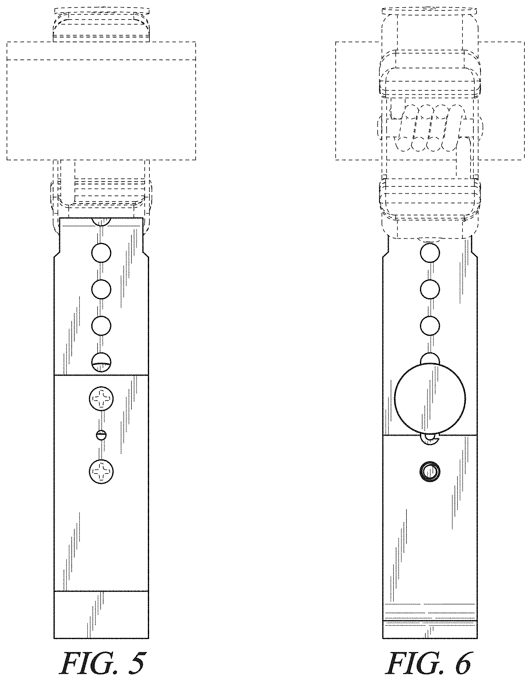
FIG. 5 is a front view thereof;
FIG. 6 is a back view thereof;
FIG. 7 is a top view thereof; and
FIG. 8 is a bottom perspective view thereof; and
FIG. 9 is another perspective view thereof showing a compacted position of the adjustable cleat.
FIG. 10 is another perspective view thereof;
FIG. 11 is a left side view thereof;
FIG. 12 is another perspective view thereof showing a rotated and compacted position of the adjustable cleat.
FIG. 13 is another perspective view thereof;
FIG. 14 is a left side view thereof; and,
FIG. 15 is an exploded view of the assembly visible during position changes.
* * * * *
D00000
D00001
D00002
D00003
D00004
D00005
D00006
D00007
D00008
D00009
D00010
D00011
D00012

D00013

XML
uspto.report is an independent third-party trademark research tool that is not affiliated, endorsed, or sponsored by the United States Patent and Trademark Office (USPTO) or any other governmental organization. The information provided by uspto.report is based on publicly available data at the time of writing and is intended for informational purposes only.
While we strive to provide accurate and up-to-date information, we do not guarantee the accuracy, completeness, reliability, or suitability of the information displayed on this site. The use of this site is at your own risk. Any reliance you place on such information is therefore strictly at your own risk.
All official trademark data, including owner information, should be verified by visiting the official USPTO website at www.uspto.gov. This site is not intended to replace professional legal advice and should not be used as a substitute for consulting with a legal professional who is knowledgeable about trademark law.