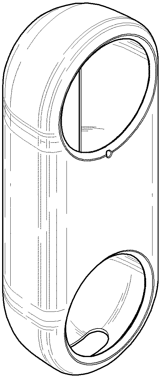
Case for electronic device
Lee , et al. April 6, 2
U.S. patent number D915,232 [Application Number D/648,174] was granted by the patent office on 2021-04-06 for case for electronic device. This patent grant is currently assigned to elago CO. LTD. The grantee listed for this patent is elago CO. LTD. Invention is credited to Chong Min Kim, Chan Woo Lee.


| United States Patent | D915,232 |
| Lee , et al. | April 6, 2021 |
Case for electronic device
Claims
CLAIM The ornamental design for a case for electronic device, as shown and described.
| Inventors: | Lee; Chan Woo (Goyang-si, KR), Kim; Chong Min (Seoul, KR) | ||||||||||
|---|---|---|---|---|---|---|---|---|---|---|---|
| Applicant: |
|
||||||||||
| Assignee: | elago CO. LTD (Goyang-si,
KR) |
||||||||||
| Appl. No.: | D/648,174 | ||||||||||
| Filed: | May 18, 2018 |
| Current U.S. Class: | D10/104.1; D3/267; D3/201; D3/219 |
| Current International Class: | 1006 |
| Field of Search: | ;D3/201,212,214,218,219,226,227,247,249,250,267,268,269,303 ;D13/103,107,108,119 ;D14/137,138R,138AA,138C,138G,172,192,203.3-203.7,217,238.1,247,248,250-253,434,440,447,496 ;D10/104.1 |
References Cited [Referenced By]
U.S. Patent Documents
| D357918 | May 1995 | Doria |
| D397865 | September 1998 | Lin |
| D484874 | January 2004 | Chang |
| D518290 | April 2006 | Andre |
| D540539 | April 2007 | Gutierrez |
| D542524 | May 2007 | Richardson |
| D551855 | October 2007 | Yeh |
| D564221 | March 2008 | Picot |
| D570593 | June 2008 | Justiss |
| D596163 | July 2009 | Madonna |
| D600228 | September 2009 | Finney |
| D633478 | March 2011 | Bolton |
| D665386 | August 2012 | Fathollahi |
| D712135 | September 2014 | Huang |
| D776640 | January 2017 | Simonian |
| D808161 | January 2018 | Herring |
| D808454 | January 2018 | Seflic |
| D830564 | October 2018 | Kim |
| D836147 | December 2018 | Rao |
| D850315 | June 2019 | Laurans |
| D885951 | June 2020 | Lee |
| 2009/0084705 | April 2009 | Justiss |
Other References
|
Elago Silicone Case designed for Google Nest Hello Doorbell, earliest photo verified review date Nov. 18, 2018, [online][site visited Aug. 20, 2020] URL: https://www.amazon.com/elago-Nest-Hello-Case-Brown/dp/B07DJ1M5L4 (Year: 2018). cited by examiner. |
Primary Examiner: Grabenstetter; L. A.
Attorney, Agent or Firm: Paratus Law Group, PLLC
Description
FIG. 1 is a front, top and left perspective view of case for electronic device showing claimed design;
FIG. 2 is a front view thereof;
FIG. 3 is a back view thereof;
FIG. 4 is a left side view thereof;
FIG. 5 is a right side view thereof;
FIG. 6 is a top view thereof;
FIG. 7 is a bottom view thereof;
FIG. 8 is a front, top and left perspective view in use; and,
FIG. 9 is a front, bottom and left perspective view in use.
The broken lines depict environment and form no part of the claimed design.
* * * * *
References
D00000
D00001
D00002
D00003
D00004
D00005
XML
uspto.report is an independent third-party trademark research tool that is not affiliated, endorsed, or sponsored by the United States Patent and Trademark Office (USPTO) or any other governmental organization. The information provided by uspto.report is based on publicly available data at the time of writing and is intended for informational purposes only.
While we strive to provide accurate and up-to-date information, we do not guarantee the accuracy, completeness, reliability, or suitability of the information displayed on this site. The use of this site is at your own risk. Any reliance you place on such information is therefore strictly at your own risk.
All official trademark data, including owner information, should be verified by visiting the official USPTO website at www.uspto.gov. This site is not intended to replace professional legal advice and should not be used as a substitute for consulting with a legal professional who is knowledgeable about trademark law.