Connector
Ganamukhi , et al. March 2, 2
U.S. patent number D911,963 [Application Number D/685,537] was granted by the patent office on 2021-03-02 for connector. This patent grant is currently assigned to Molex, LLC. The grantee listed for this patent is Molex, LLC. Invention is credited to Ishwarappa Ganamukhi, Pierre Perez.


View All Diagrams
| United States Patent | D911,963 |
| Ganamukhi , et al. | March 2, 2021 |
Connector
Claims
CLAIM The ornamental design for a connector, as shown and described.
| Inventors: | Ganamukhi; Ishwarappa (Bangalore, IN), Perez; Pierre (Aurora, IL) | ||||||||||
|---|---|---|---|---|---|---|---|---|---|---|---|
| Applicant: |
|
||||||||||
| Assignee: | Molex, LLC (Lisle, IL) |
||||||||||
| Appl. No.: | D/685,537 | ||||||||||
| Filed: | March 28, 2019 |
| Current U.S. Class: | D13/133; D13/147 |
| Current International Class: | 1303 |
| Field of Search: | ;D13/133,146,147,153,154,184 |
References Cited [Referenced By]
U.S. Patent Documents
| D388767 | January 1998 | Akins |
| D389121 | January 1998 | Kuprewicz |
| D524751 | July 2006 | Lee |
| D655677 | March 2012 | Gouhl |
| D676386 | February 2013 | Gassauer |
| D676392 | February 2013 | Gassauer |
| D748580 | February 2016 | Endo |
| D748588 | February 2016 | Endo |
| D791706 | July 2017 | Li |
| D791707 | July 2017 | Li |
| D792851 | July 2017 | Li |
| D792852 | July 2017 | Li |
| D792853 | July 2017 | Li |
| D802538 | November 2017 | Li |
| D803162 | November 2017 | Li |
| D899367 | October 2020 | Thyagaraj |
| D899369 | October 2020 | Thyagaraj |
| D899370 | October 2020 | Thyagaraj |
| D900030 | October 2020 | Thyagaraj |
| D205298-006 | Mar 2020 | WO | |||
| D205298-007 | Mar 2020 | WO | |||
Assistant Examiner: Chong; Michael
Attorney, Agent or Firm: Banner & Witcoff, Ltd.
Description
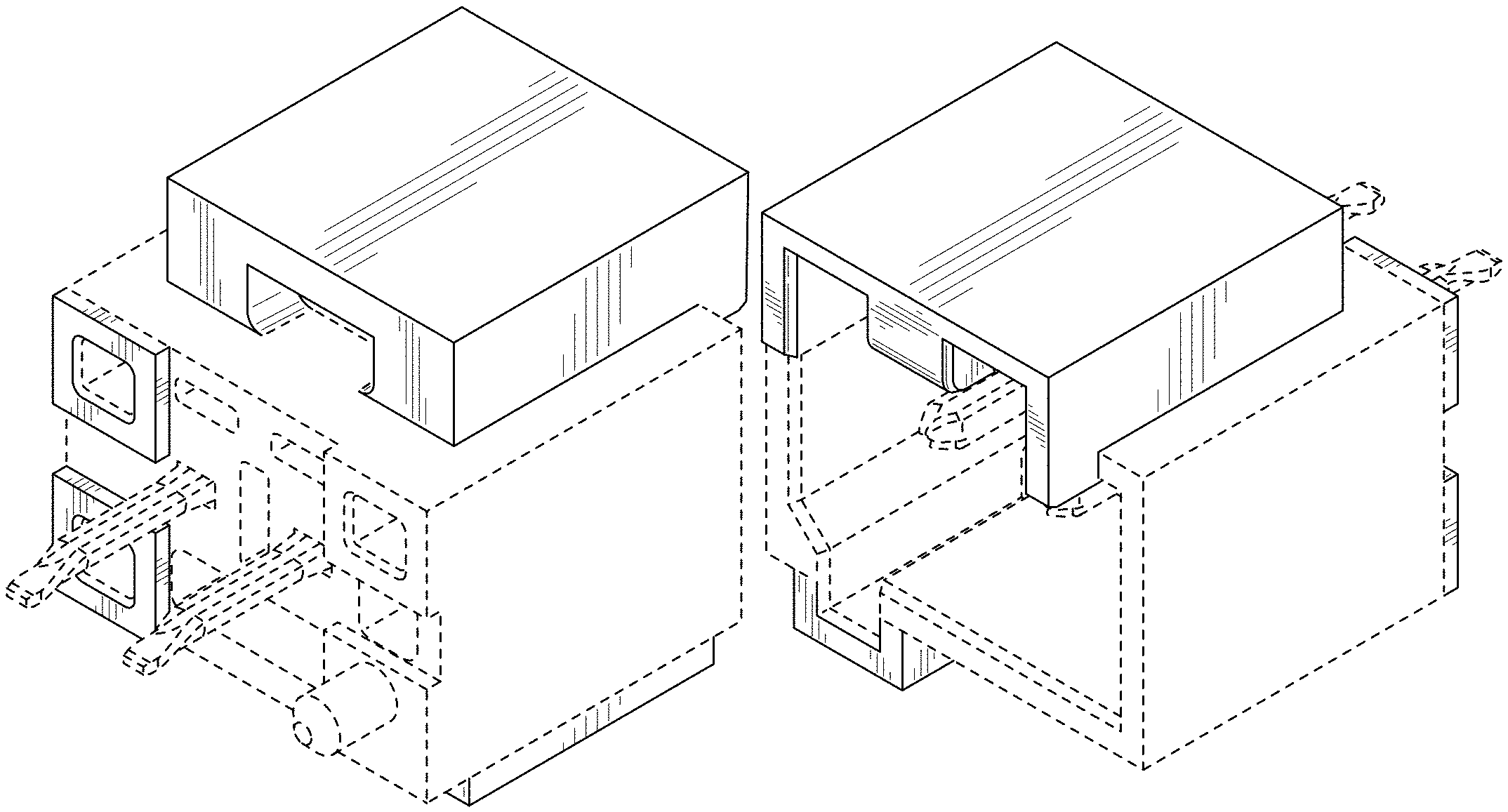
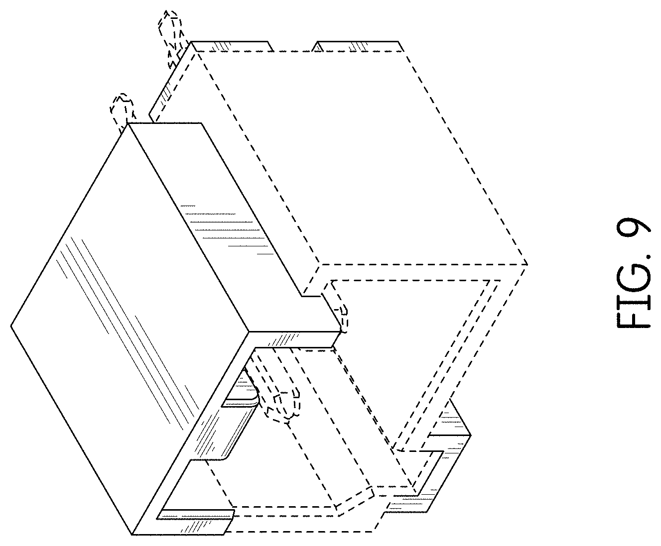
FIG. 1 is a front right perspective view of a connector showing our new design;
FIG. 2 is a front left perspective view thereof;
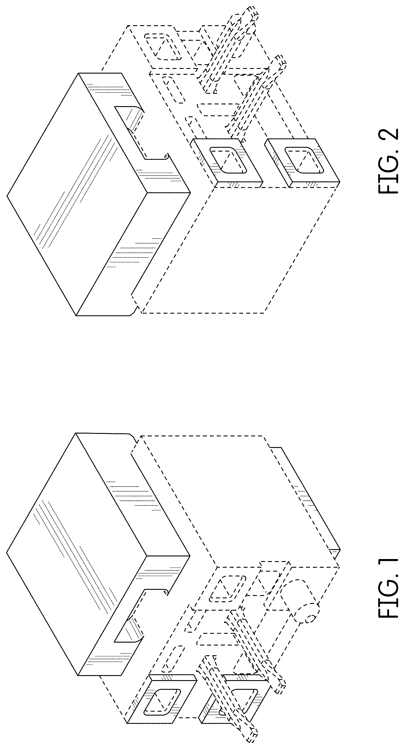
FIG. 3 is a rear view thereof;
FIG. 4 is a front view thereof;
FIG. 5 is a right side view thereof;
FIG. 6 is a left side view thereof;
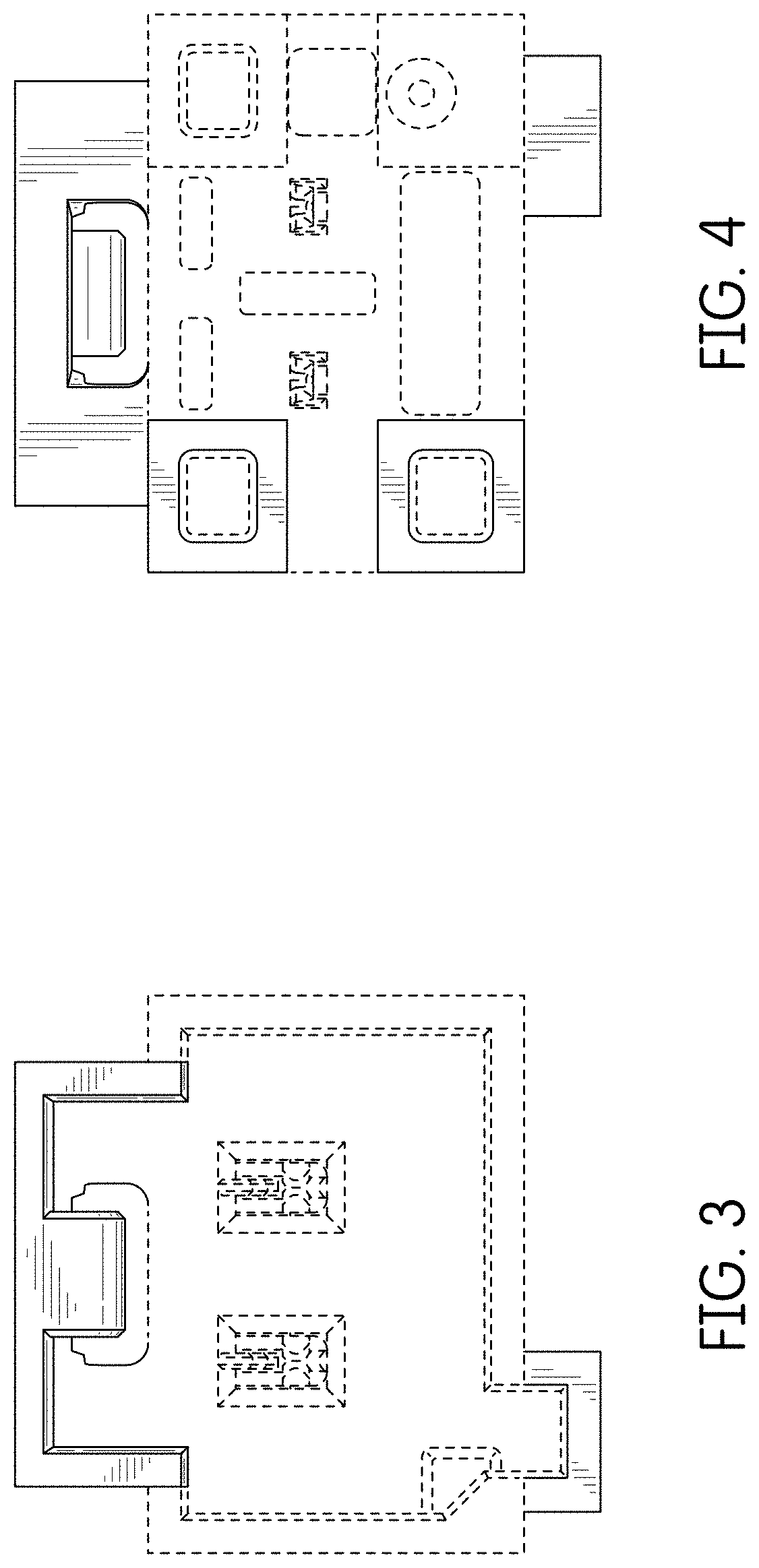
FIG. 7 is a top view thereof;
FIG. 8 is a bottom view thereof;
FIG. 9 is a rear perspective view thereof;
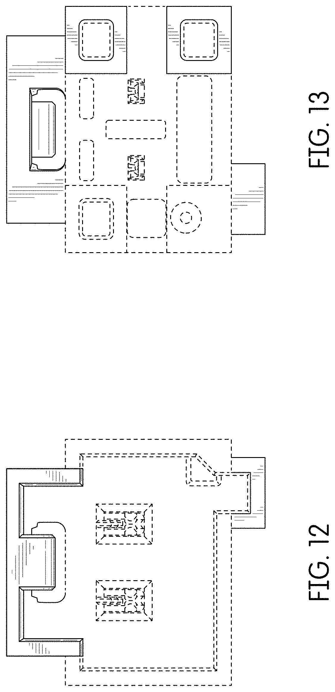
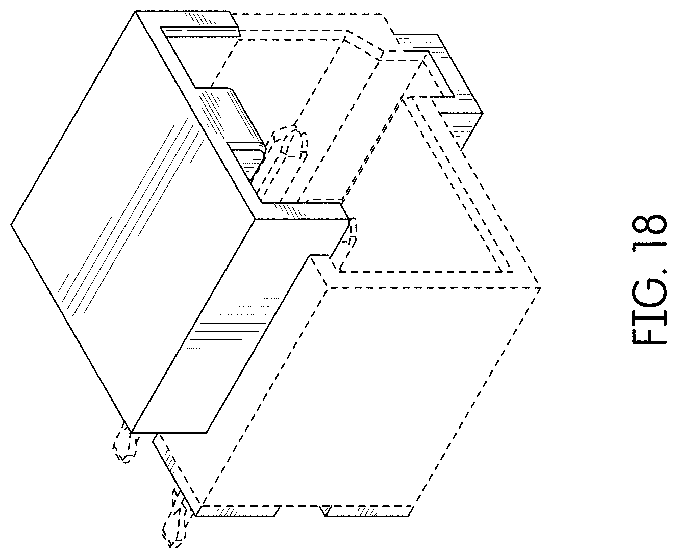
FIG. 10 is a front left perspective view of an alternate embodiment of the connector showing our new design which is a mirror image of the connector of FIGS. 1-9;
FIG. 11 is a front right perspective view thereof;
FIG. 12 is a rear view thereof;
FIG. 13 is a front view thereof;
FIG. 14 is a right side view thereof;
FIG. 15 is a left side view thereof;
FIG. 16 is a top view thereof;
FIG. 17 is a bottom view thereof;
FIG. 18 is a rear perspective view thereof;
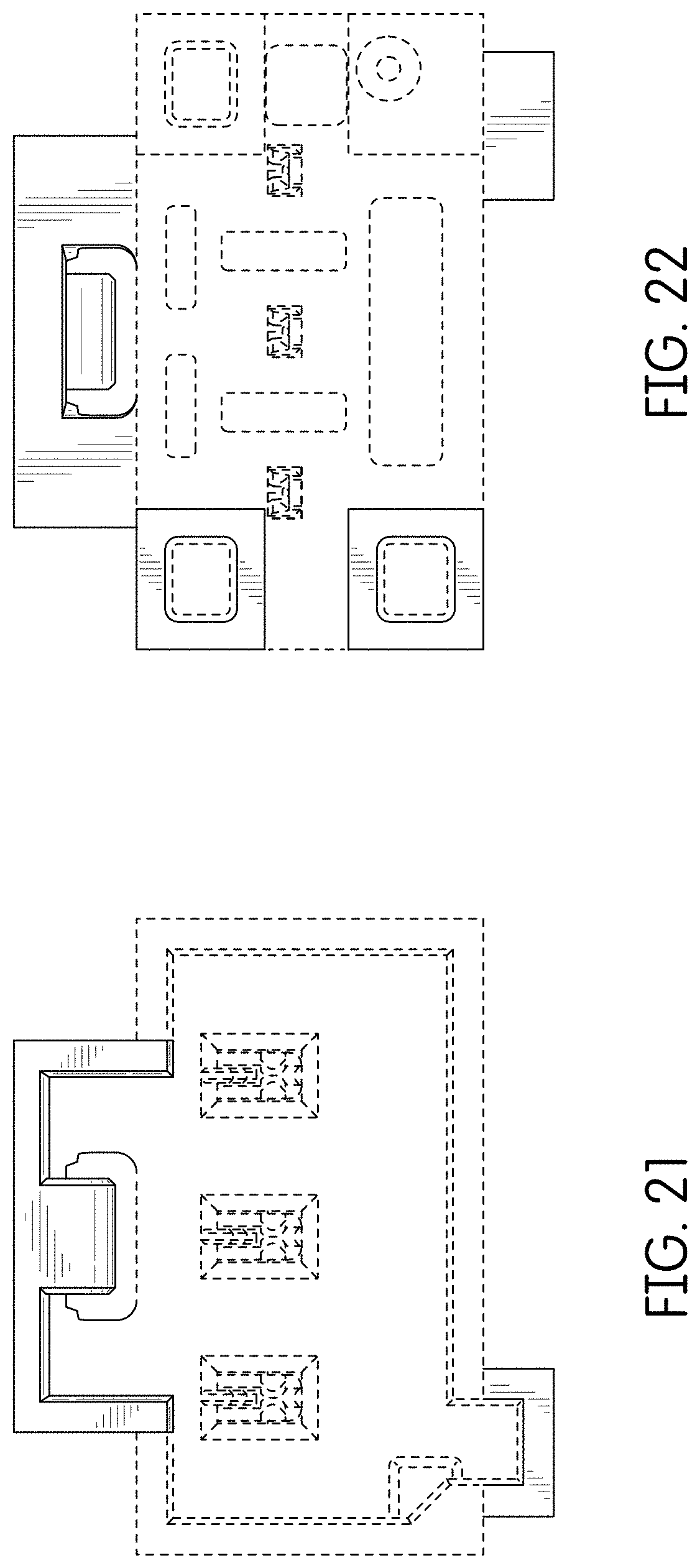
FIG. 19 is a front right perspective view of an alternate embodiment of the connector showing our new design;
FIG. 20 is a front left perspective view thereof;
FIG. 21 is a rear view thereof;
FIG. 22 is a front view thereof;
FIG. 23 is a right side view thereof;
FIG. 24 is a left side view thereof;
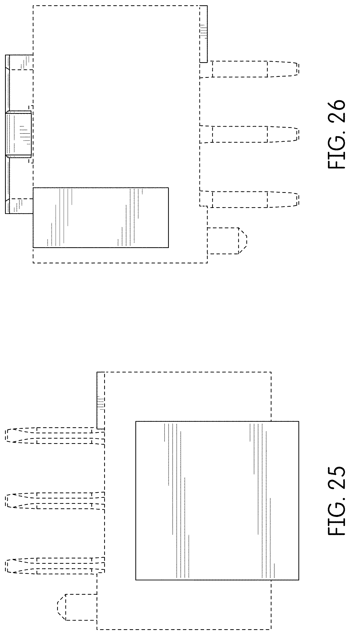
FIG. 25 is a top view thereof;
FIG. 26 is a bottom view thereof;
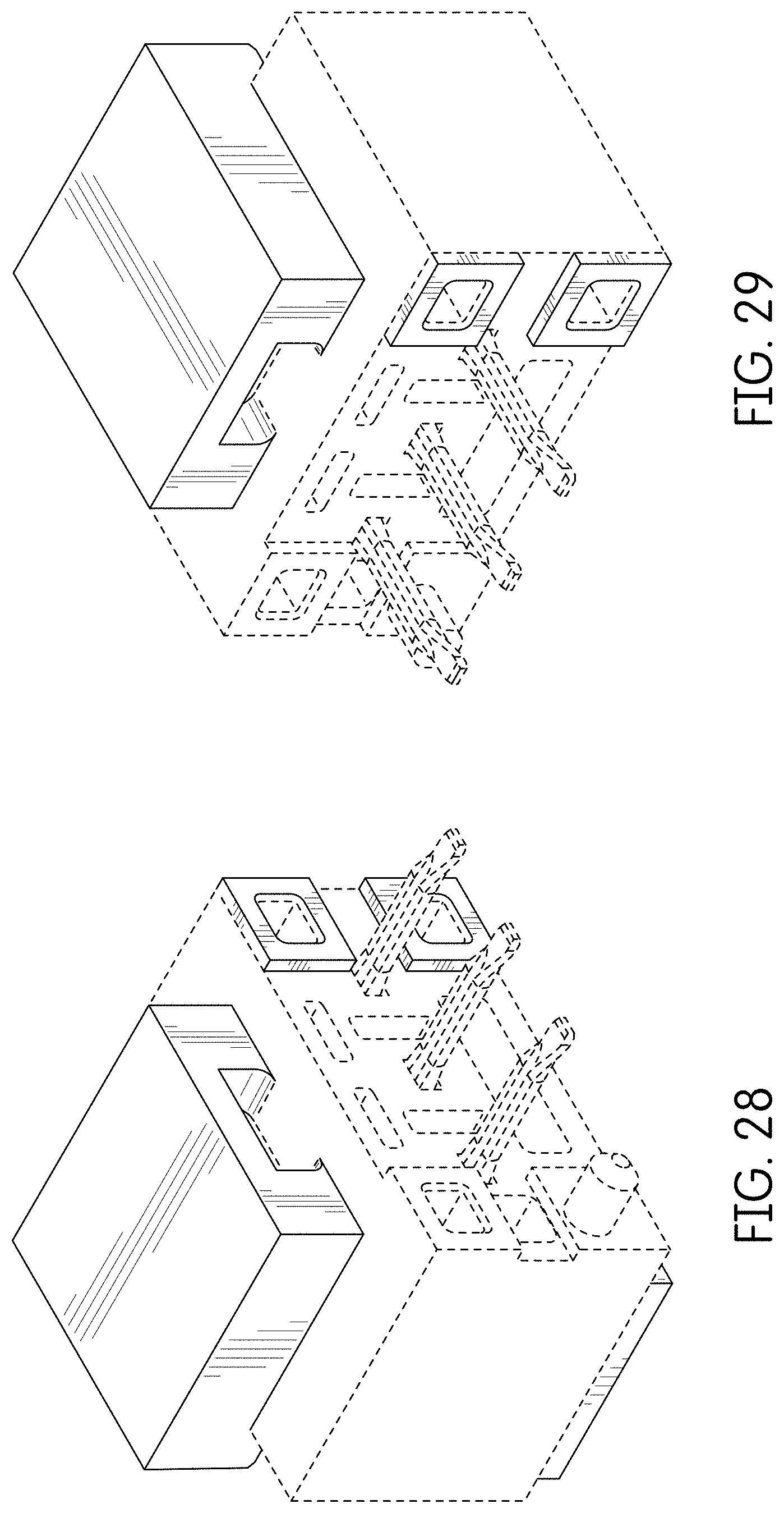
FIG. 27 is a rear perspective view thereof;
FIG. 28 is a front left perspective view of an alternate embodiment of the connector showing our new design which is a mirror image of the connector of FIGS. 19-27;
FIG. 29 is a front right perspective view thereof;
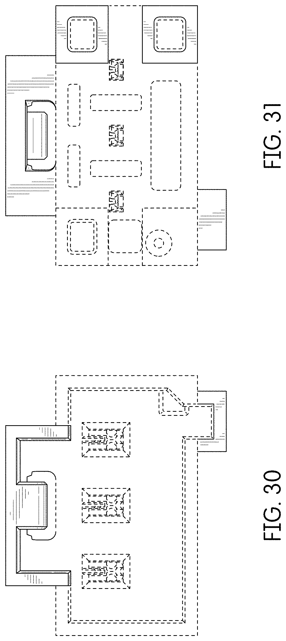
FIG. 30 is a rear view thereof;
FIG. 31 is a front view thereof;
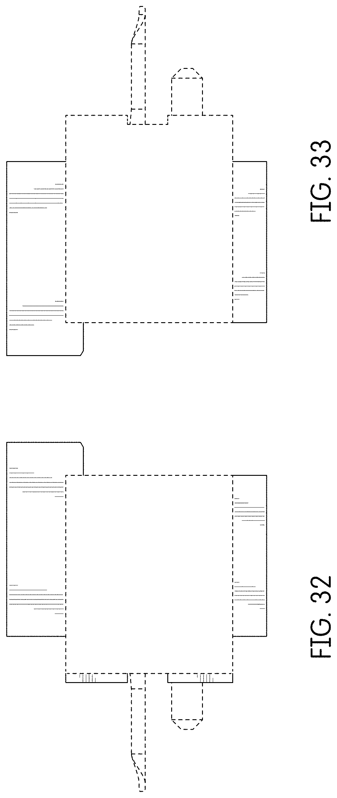
FIG. 32 is a right side view thereof;
FIG. 33 is a left side view thereof;
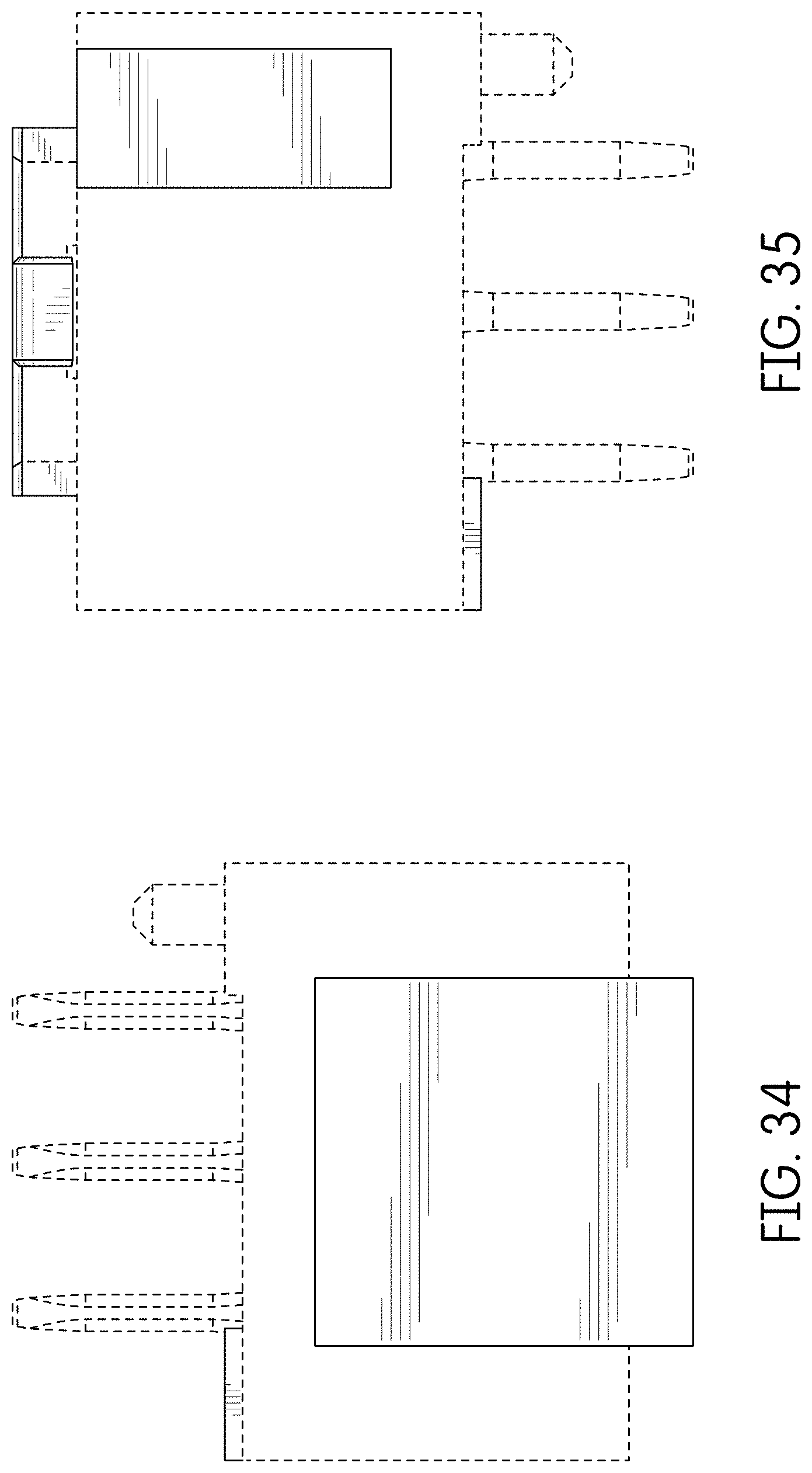
FIG. 34 is a top view thereof;
FIG. 35 is a bottom view thereof;
FIG. 36 is a rear perspective view thereof;
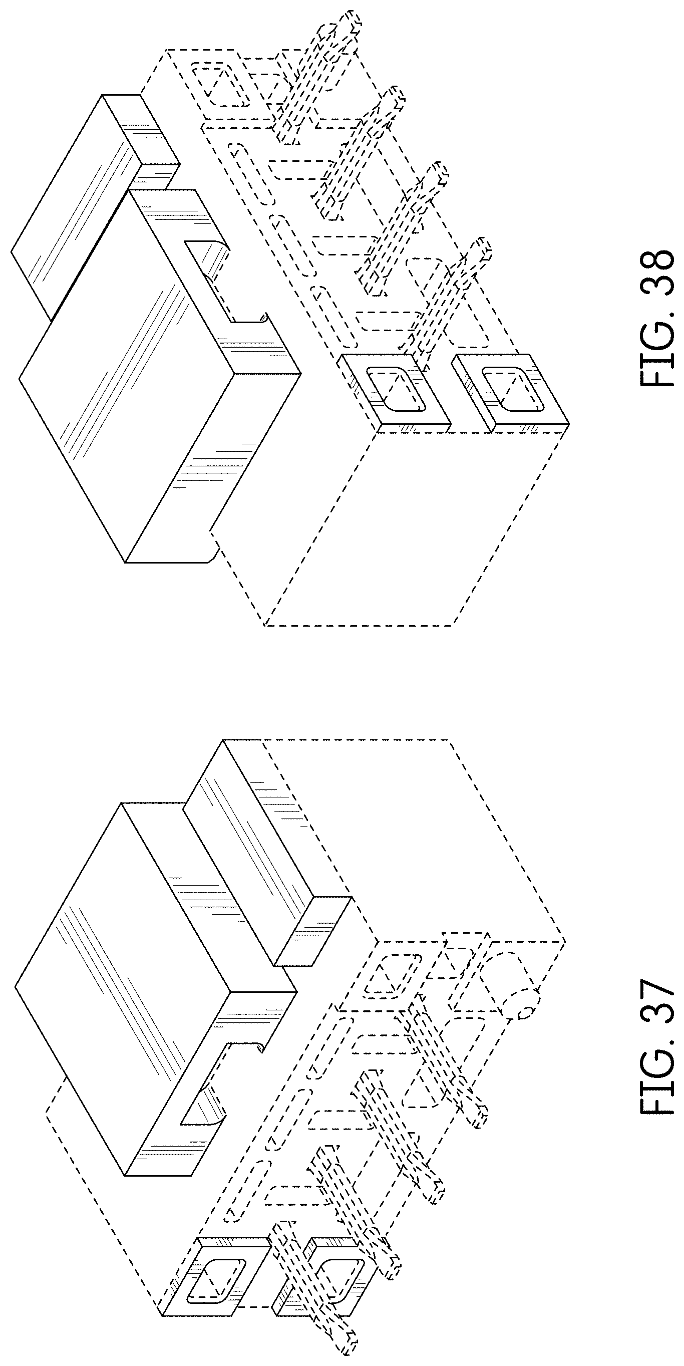
FIG. 37 is a front right perspective view of an alternate embodiment of the connector showing our new design;
FIG. 38 is a front left perspective view thereof;
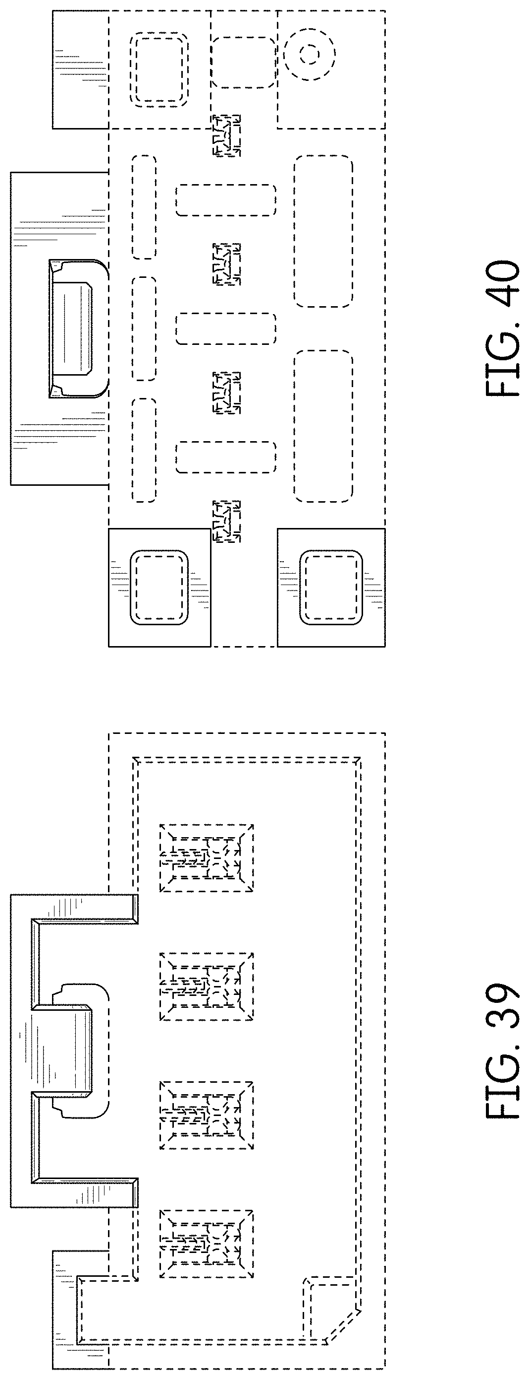
FIG. 39 is a rear view thereof;
FIG. 40 is a front view thereof;
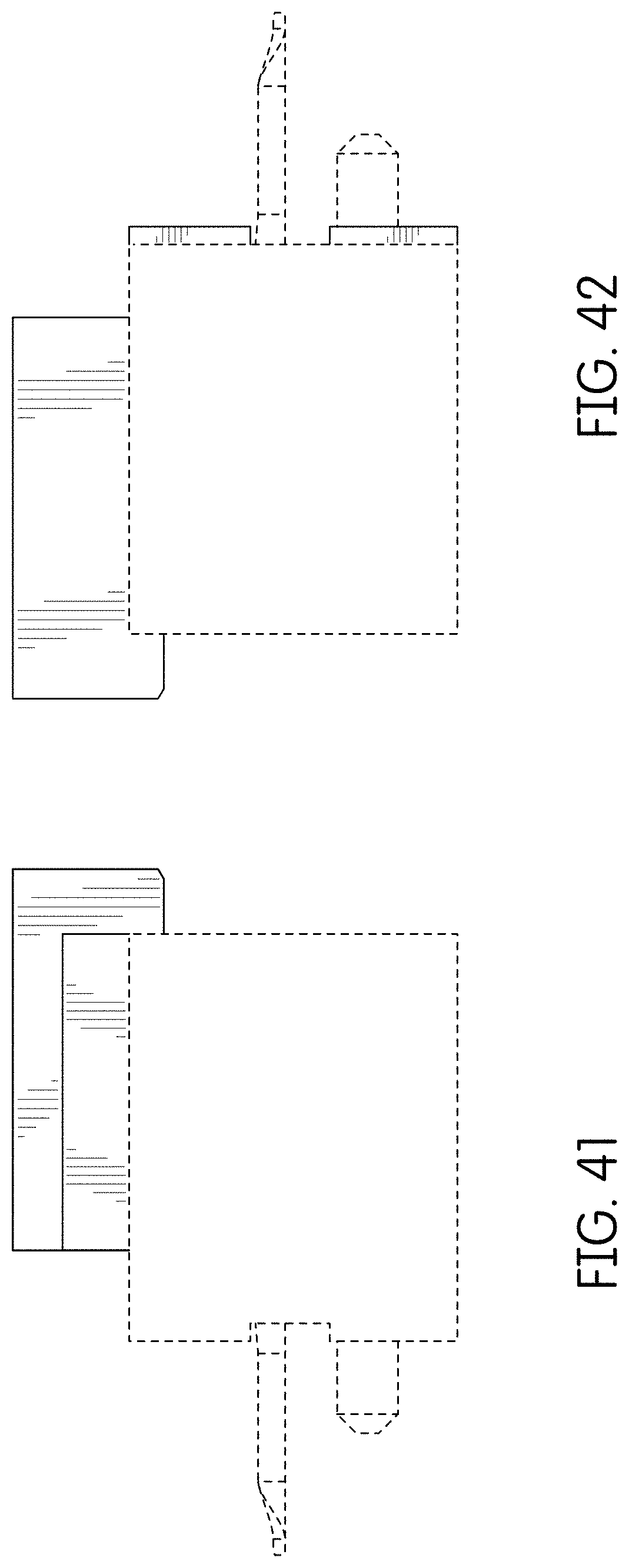
FIG. 41 is a right side view thereof;
FIG. 42 is a left side view thereof;
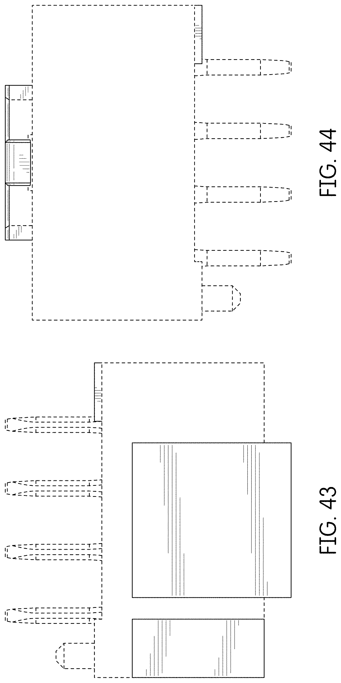
FIG. 43 is a top view thereof;
FIG. 44 is a bottom view thereof;
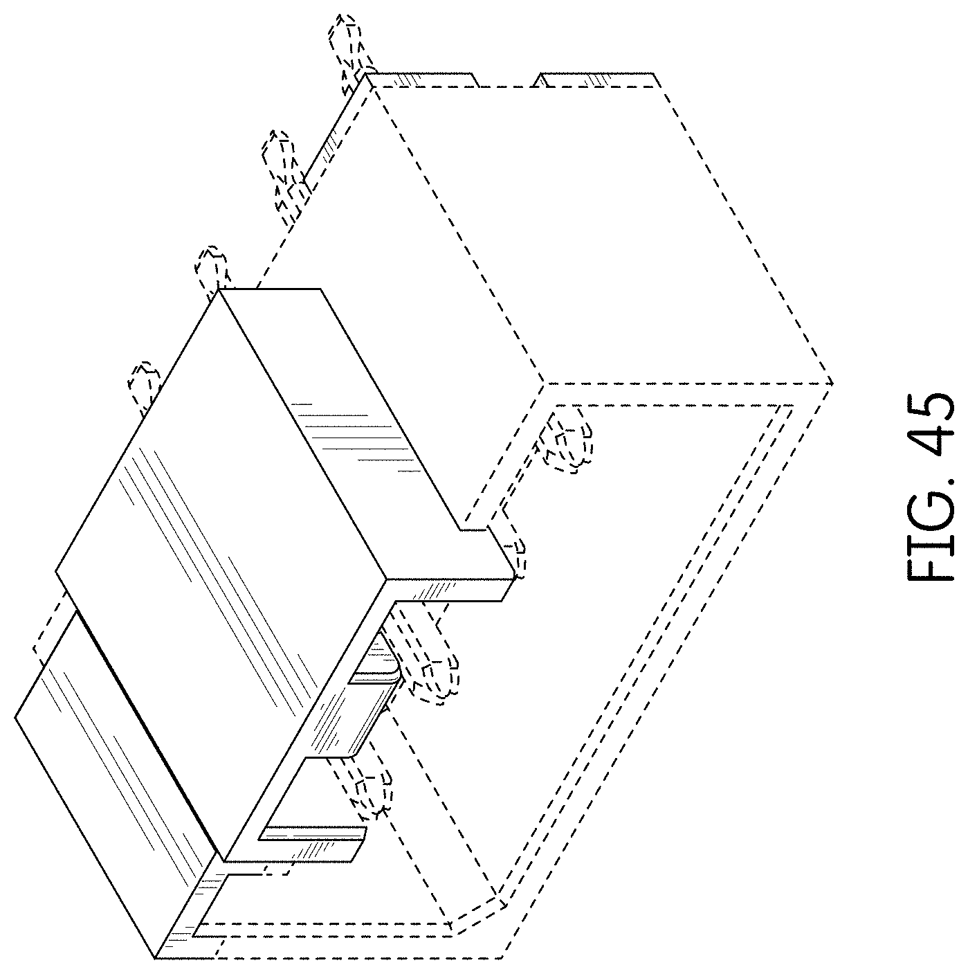
FIG. 45 is a rear perspective view thereof;
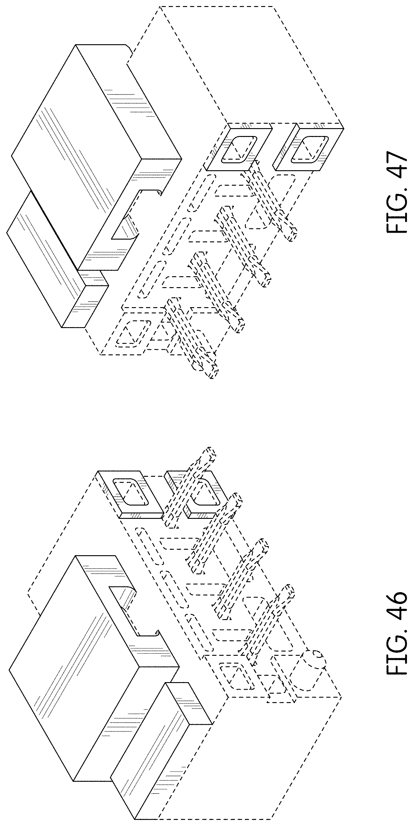
FIG. 46 is a front left perspective view of an alternate embodiment of the connector showing our new design which is a mirror image of the connector of FIGS. 37-45;
FIG. 47 is a front right perspective view thereof;
FIG. 48 is a rear view thereof;
FIG. 49 is a front view thereof;
FIG. 50 is a right side view thereof;
FIG. 51 is a left side view thereof;
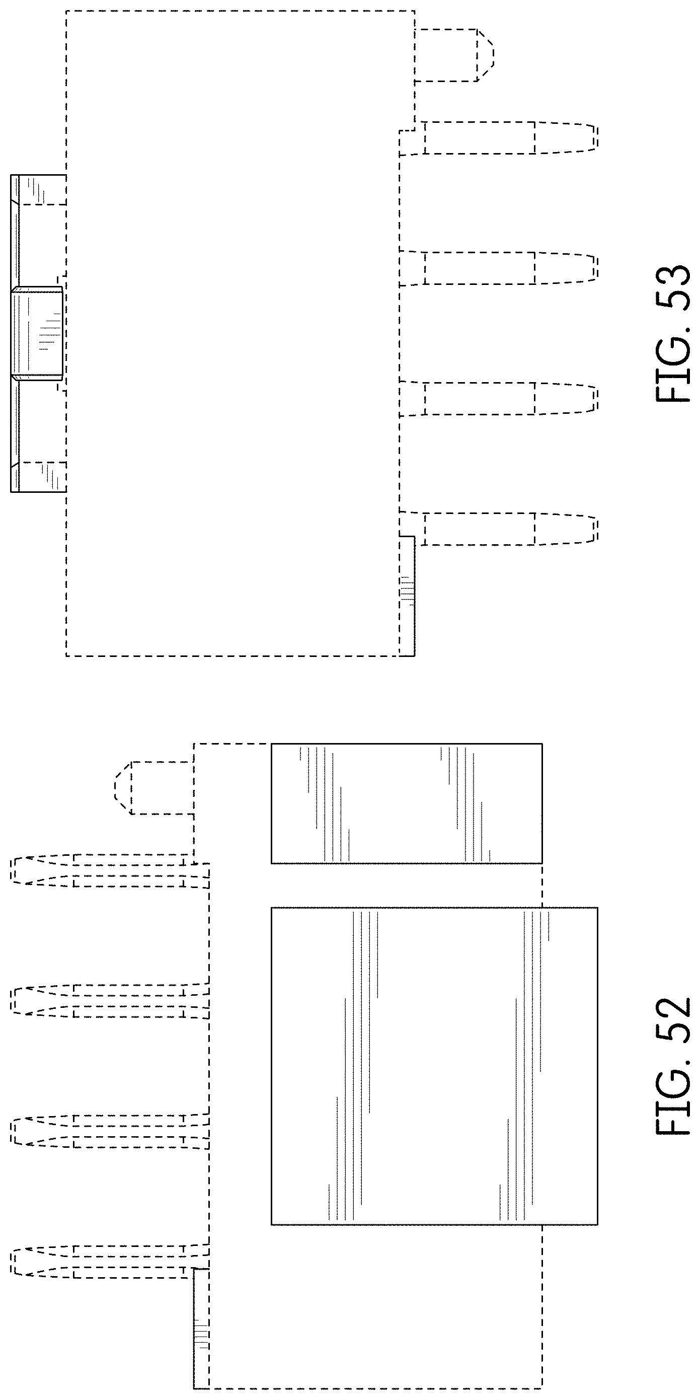
FIG. 52 is a top view thereof;
FIG. 53 is a bottom view thereof;
FIG. 54 is a rear perspective view thereof;
FIG. 55 is a front right perspective view of an alternate embodiment of the connector showing our new design;
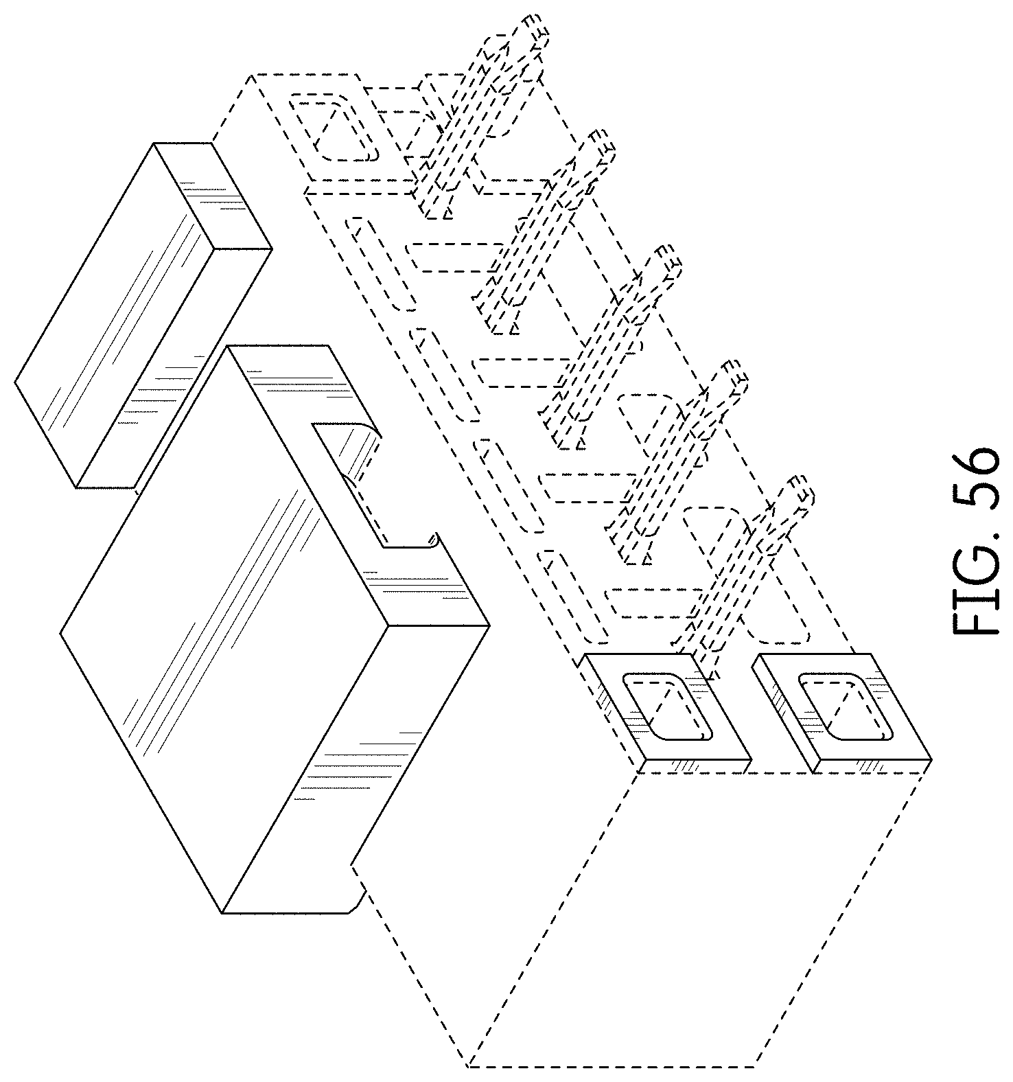
FIG. 56 is a front left perspective view thereof;
FIG. 57 is a rear view thereof;
FIG. 58 is a front view thereof;
FIG. 59 is a right side view thereof;
FIG. 60 is a left side view thereof;
FIG. 61 is a top view thereof;
FIG. 62 is a bottom view thereof;
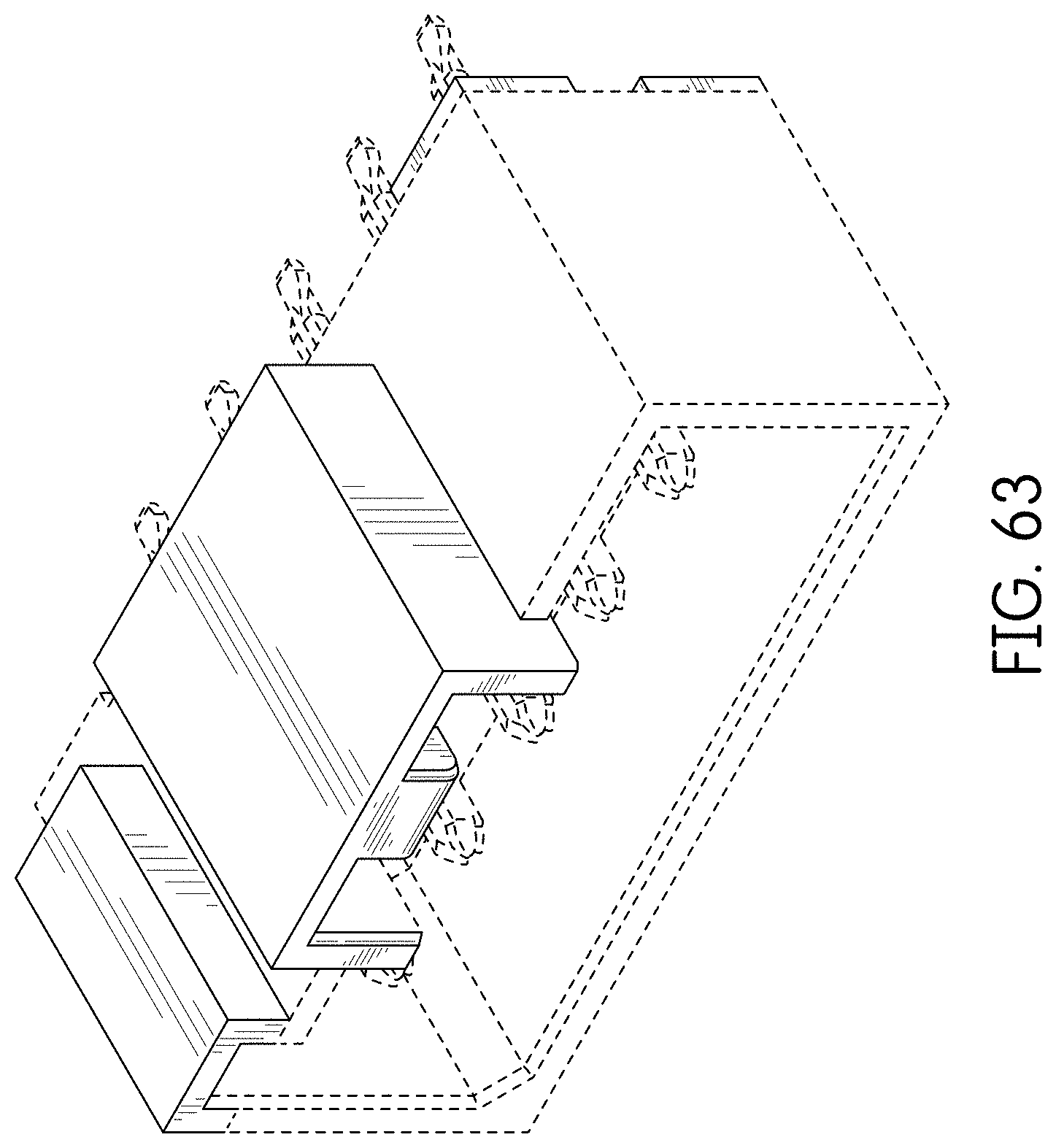
FIG. 63 is a rear perspective view thereof;
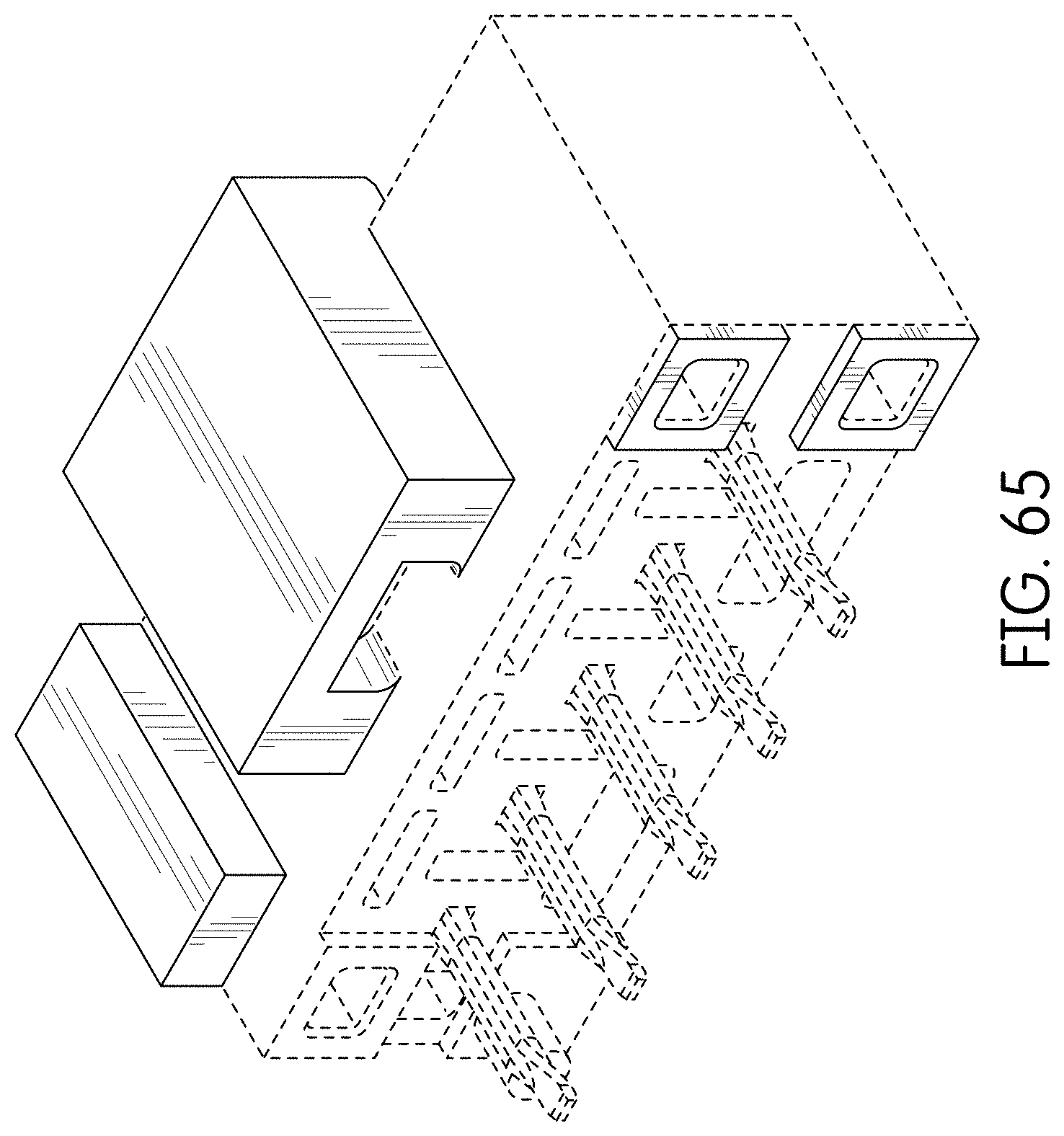
FIG. 64 is a front left perspective view of an alternate embodiment of the connector showing our new design which is a mirror image of the connector of FIGS. 55-63;
FIG. 65 is a front right perspective view thereof;
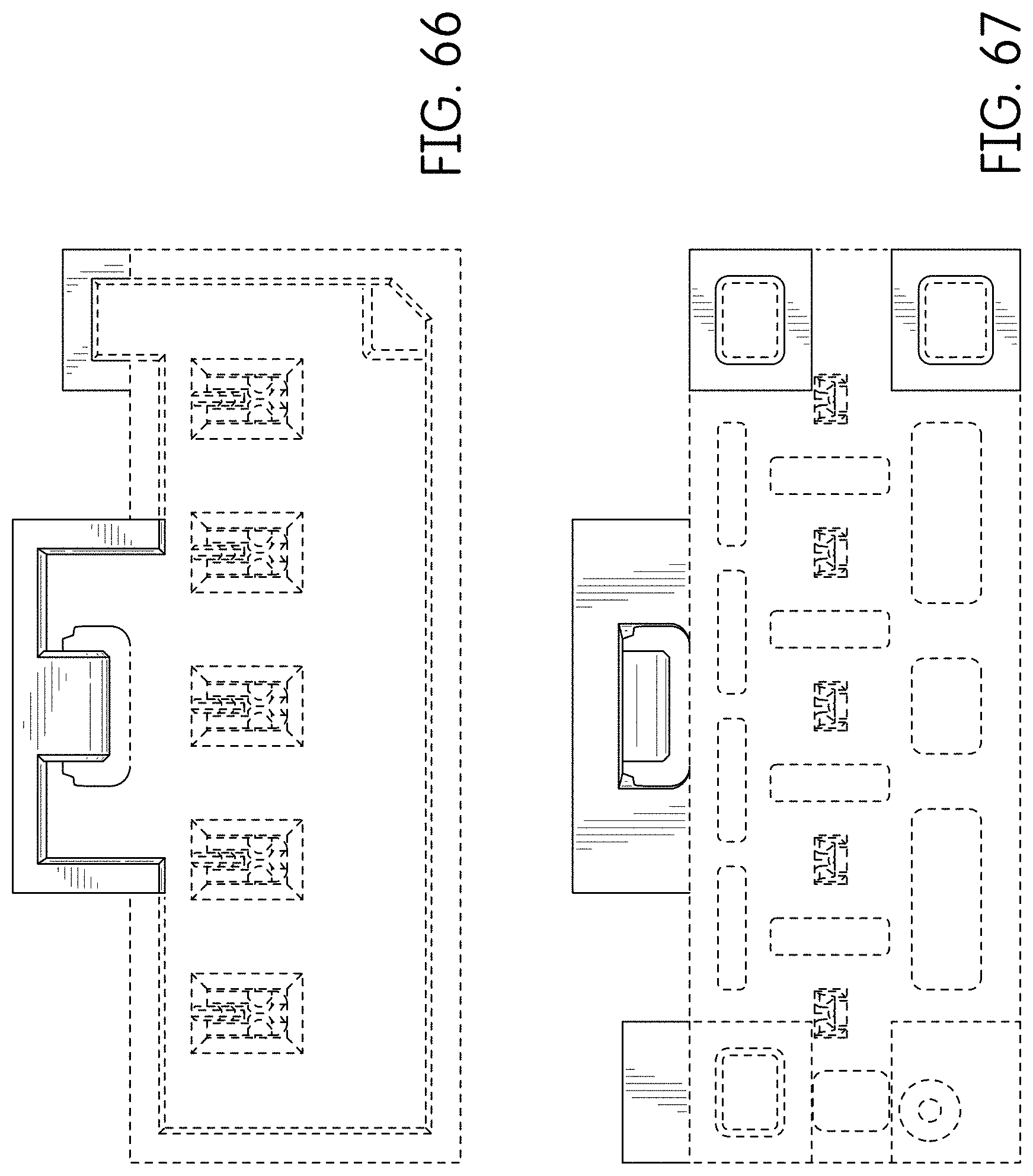
FIG. 66 is a rear view thereof;
FIG. 67 is a front view thereof;
FIG. 68 is a right side view thereof;
FIG. 69 is a left side view thereof;
FIG. 70 is a top view thereof;
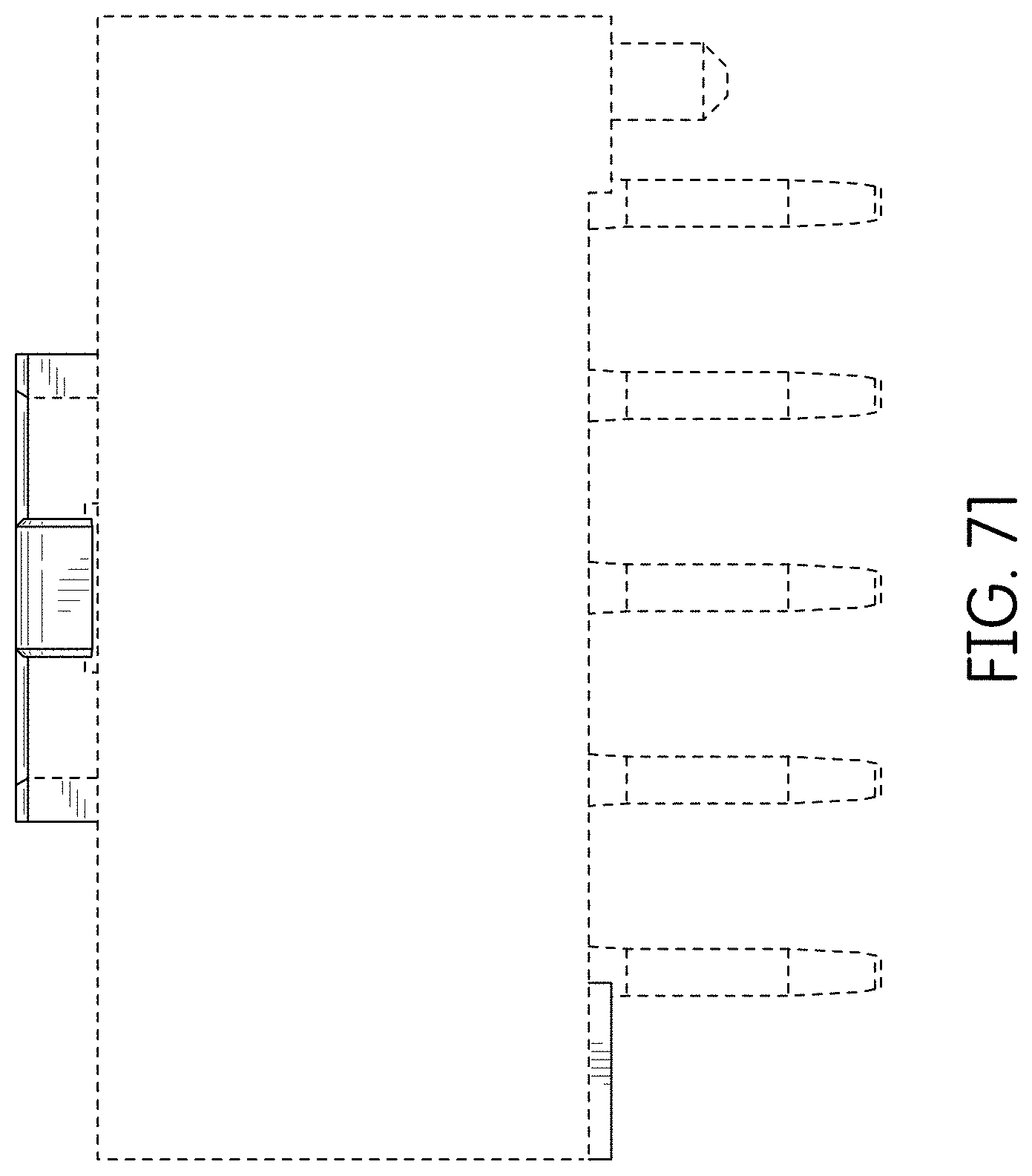
FIG. 71 is a bottom view thereof;
FIG. 72 is a rear perspective view thereof;
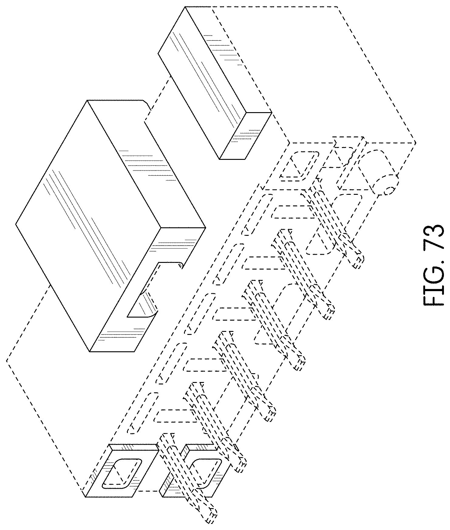
FIG. 73 is a front right perspective view of an alternate embodiment of the connector showing our new design;
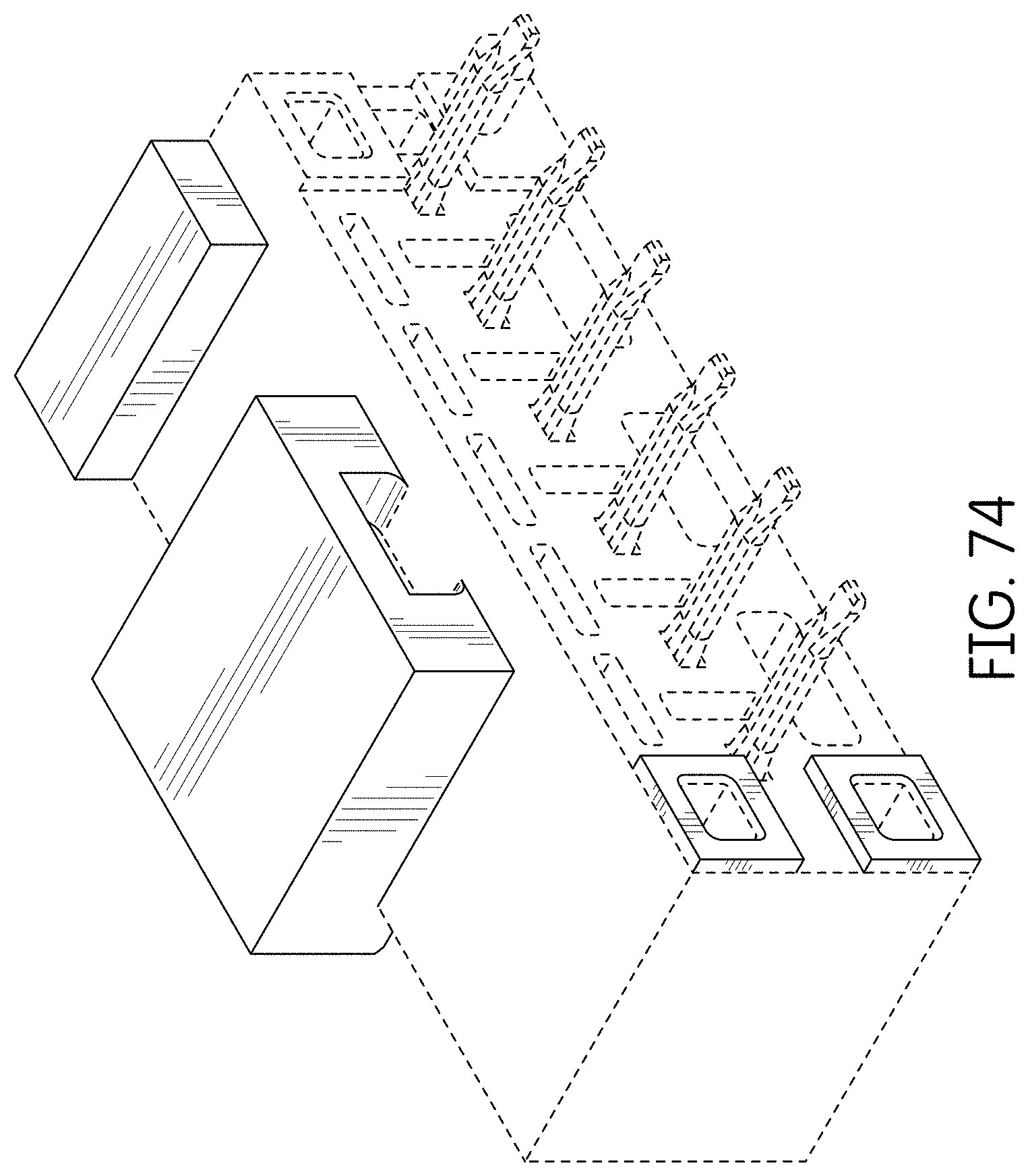
FIG. 74 is a front left perspective view thereof;
FIG. 75 is a rear view thereof;
FIG. 76 is a front view thereof;
FIG. 77 is a right side view thereof;
FIG. 78 is a left side view thereof;
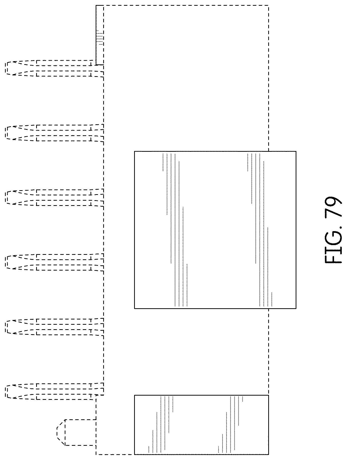
FIG. 79 is a top view thereof;
FIG. 80 is a bottom view thereof;
FIG. 81 is a rear perspective view thereof;
FIG. 82 is a front left perspective view of an alternate embodiment of the connector showing our new design which is a mirror image of the connector of FIGS. 73-81;
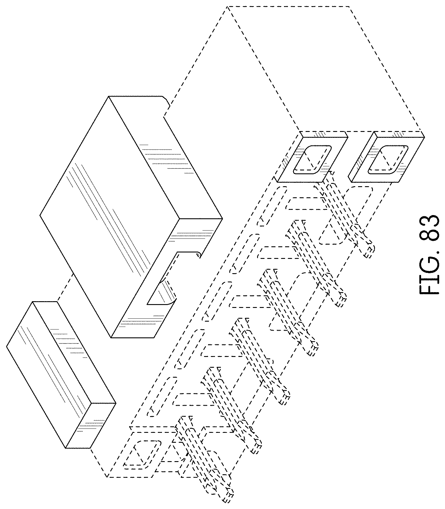
FIG. 83 is a front right perspective view thereof;
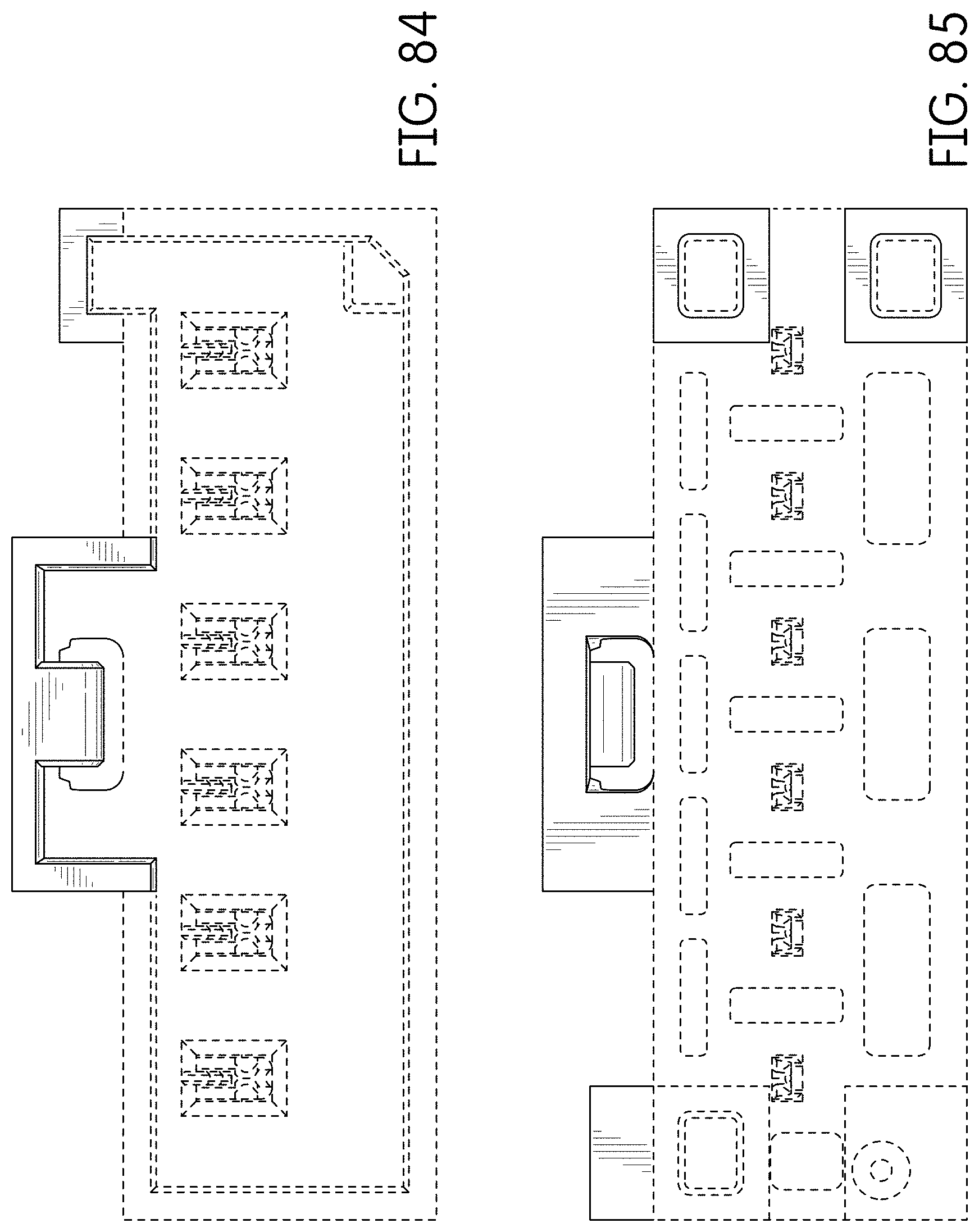
FIG. 84 is a rear view thereof;
FIG. 85 is a front view thereof;
FIG. 86 is a right side view thereof;
FIG. 87 is a left side view thereof;
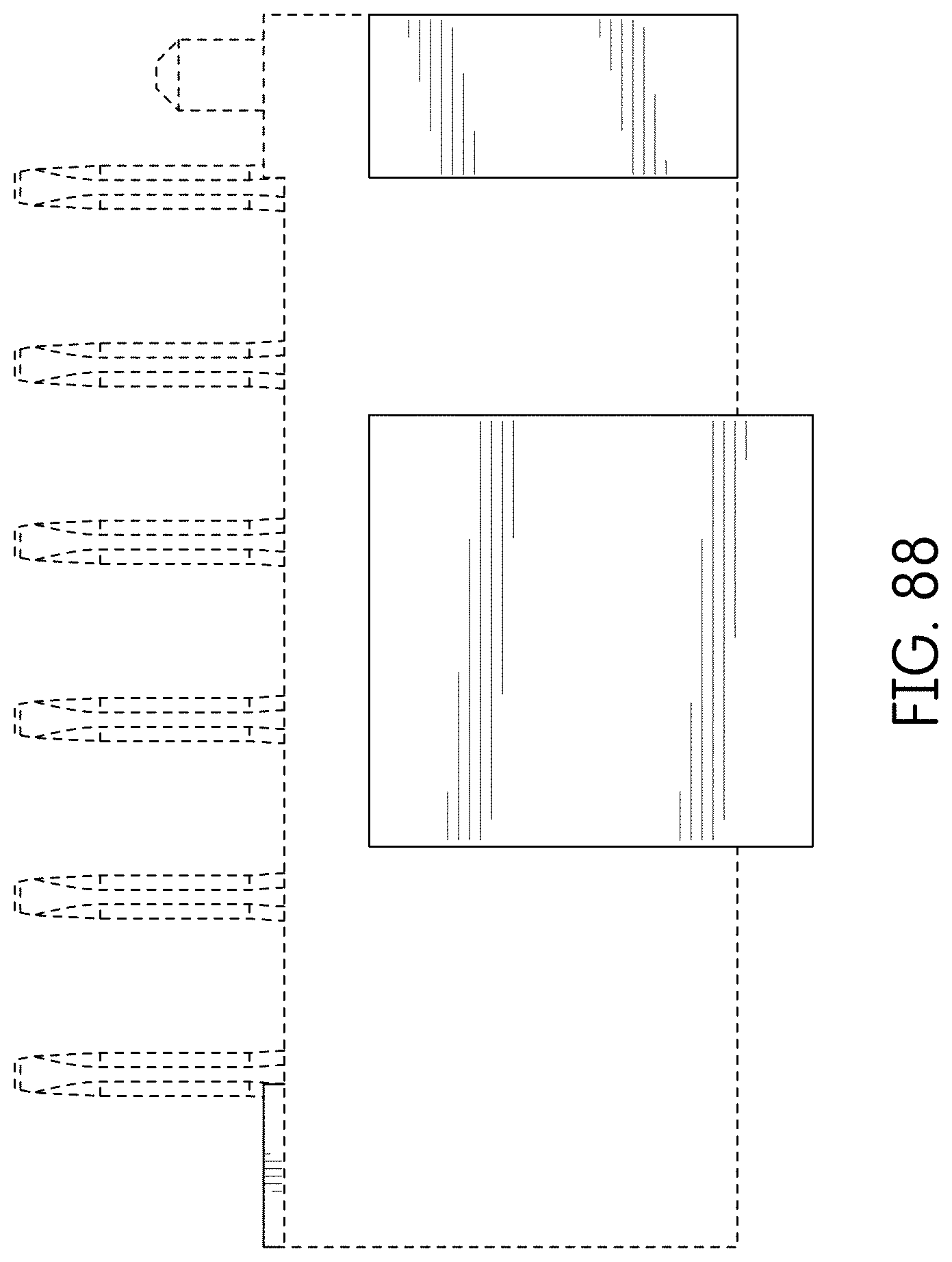
FIG. 88 is a top view thereof;
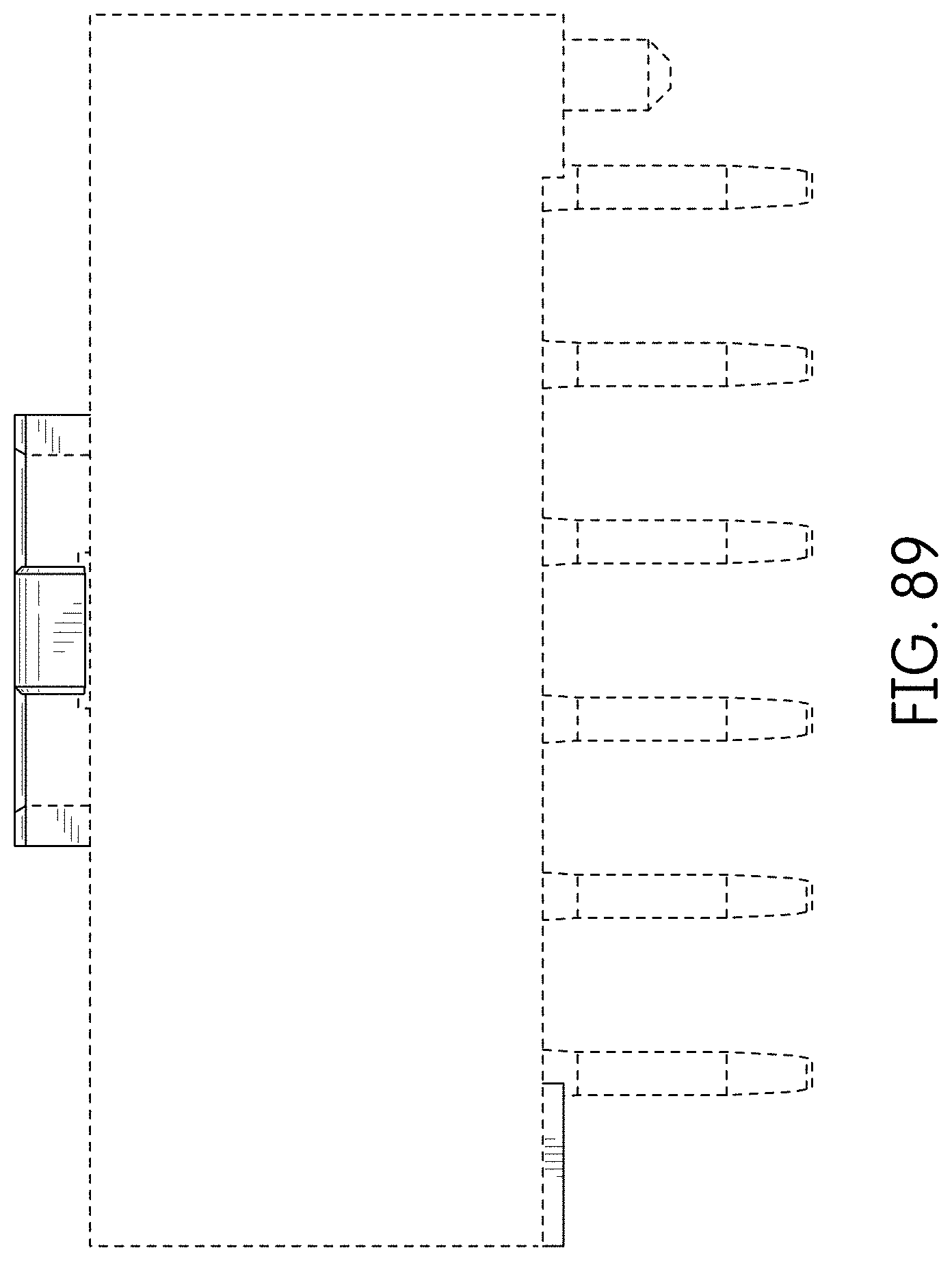
FIG. 89 is a bottom view thereof;
FIG. 90 is a rear perspective view thereof;
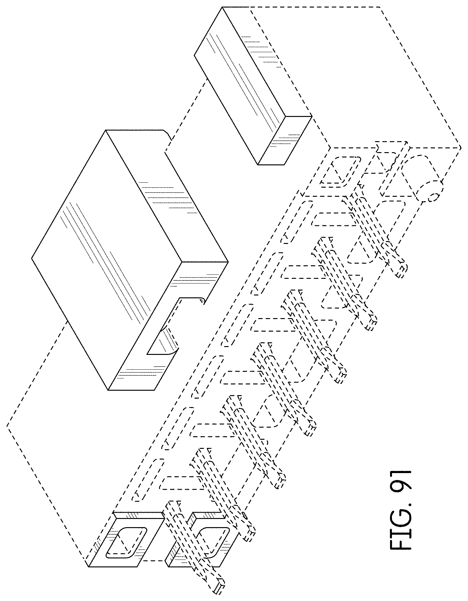
FIG. 91 is a front right perspective view of an alternate embodiment of the connector showing our new design;
FIG. 92 is a front left perspective view thereof;
FIG. 93 is a rear view thereof;
FIG. 94 is a front view thereof;
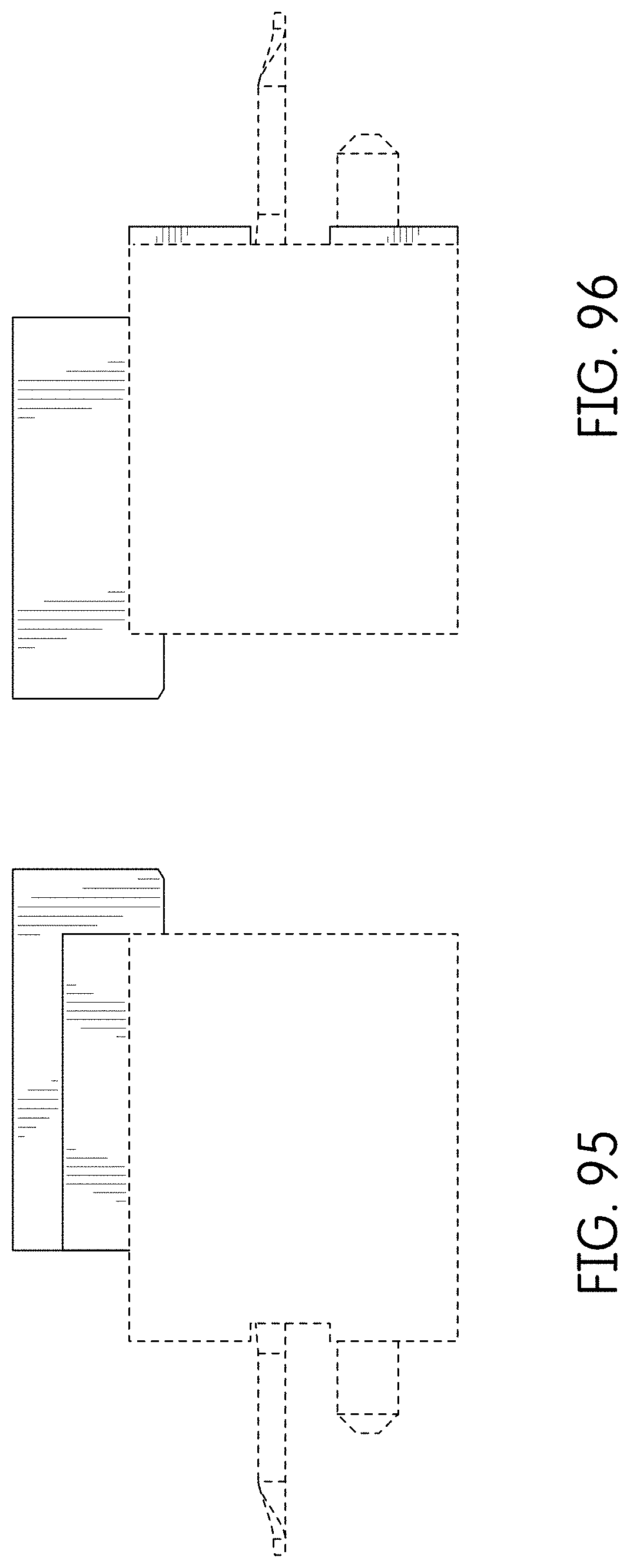
FIG. 95 is a right side view thereof;
FIG. 96 is a left side view thereof;
FIG. 97 is a top view thereof;
FIG. 98 is a bottom view thereof;
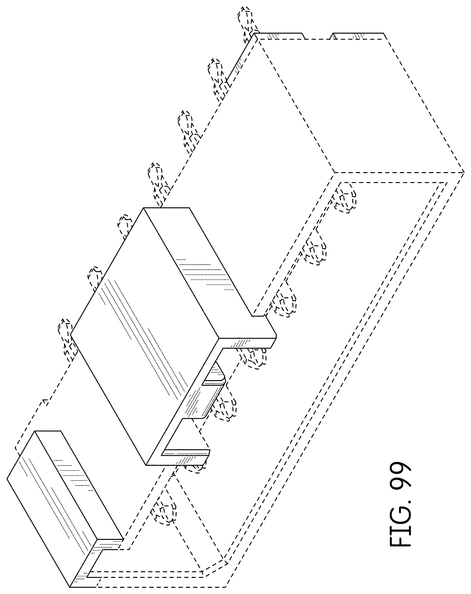
FIG. 99 is a rear perspective view thereof;
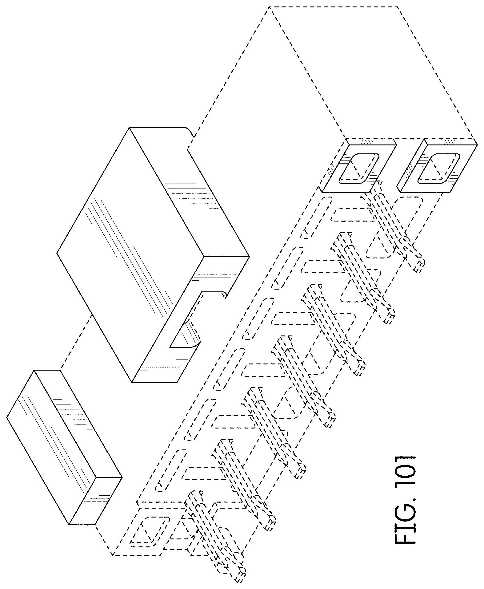
FIG. 100 is a front left perspective view of an alternate embodiment of the connector showing our new design which is a mirror image of the connector of FIGS. 91-99;
FIG. 101 is a front right perspective view thereof;
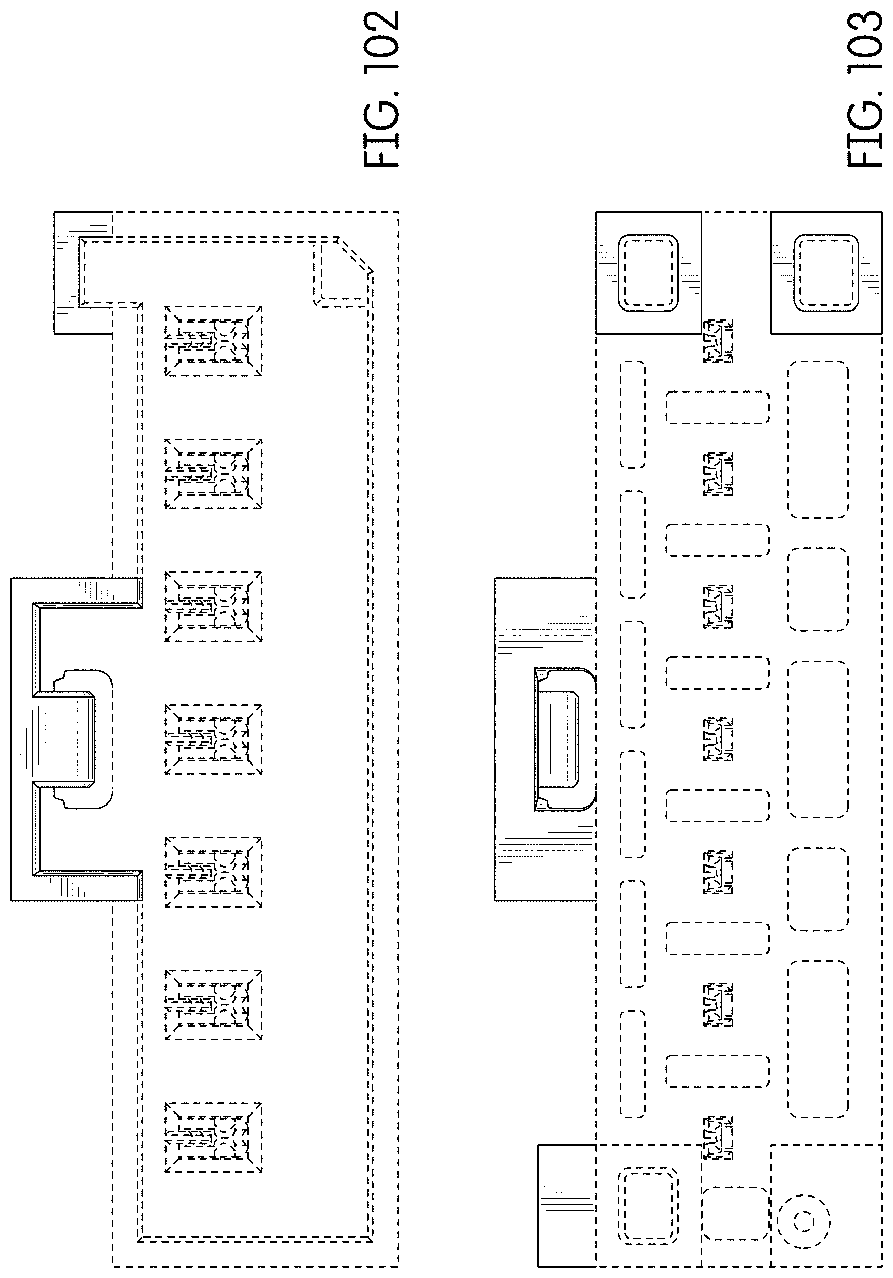
FIG. 102 is a rear view thereof;
FIG. 103 is a front view thereof;
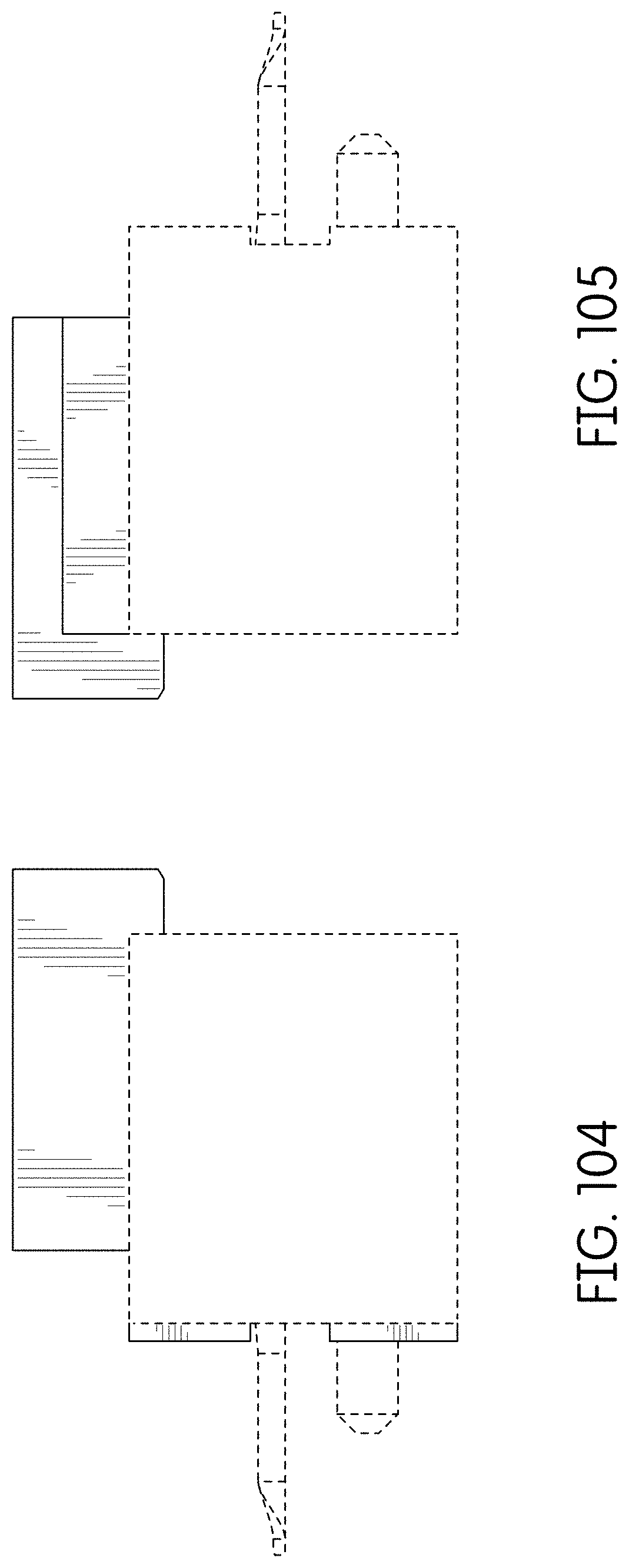
FIG. 104 is a right side view thereof;
FIG. 105 is a left side view thereof;
FIG. 106 is a top view thereof;
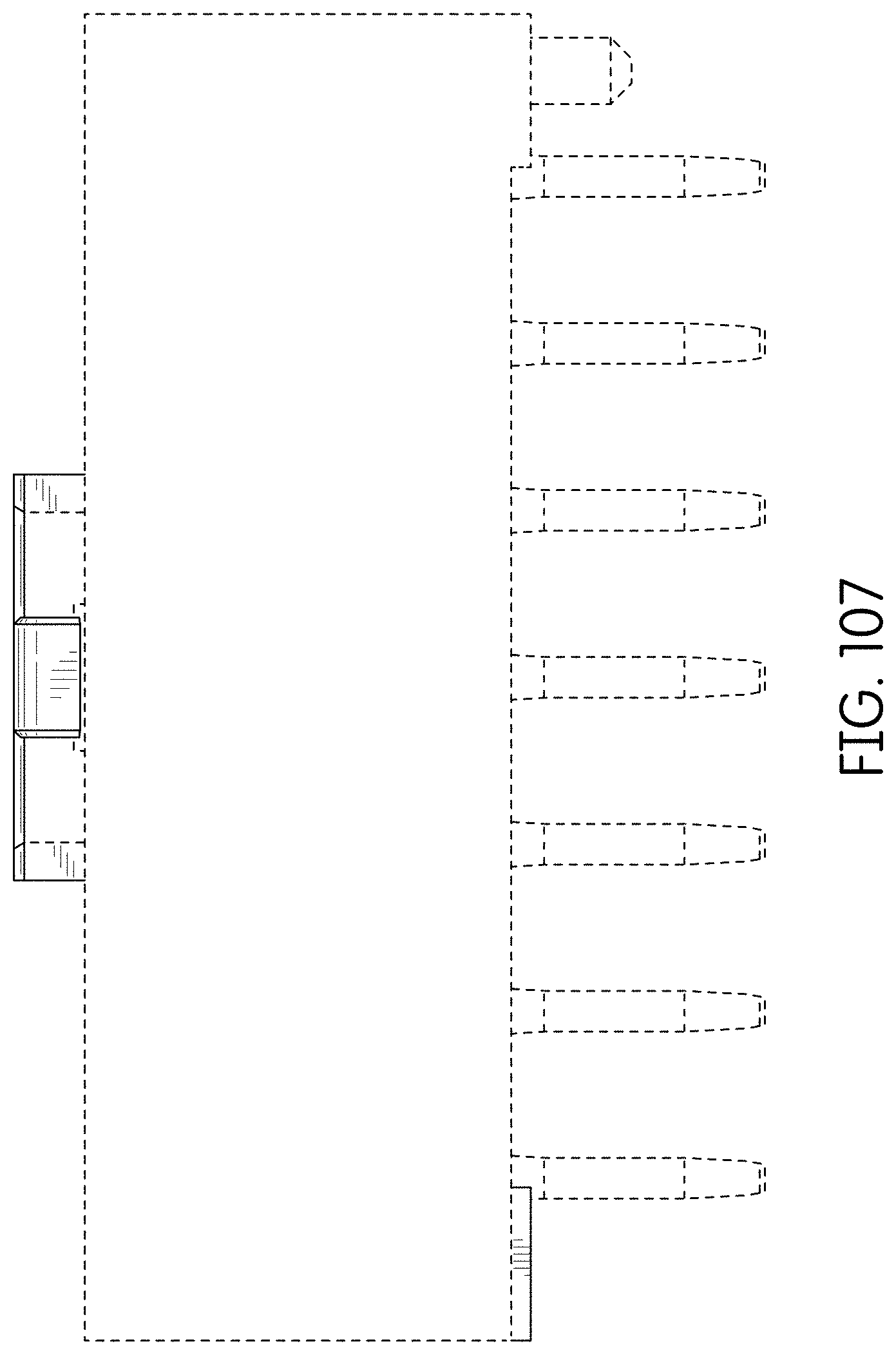
FIG. 107 is a bottom view thereof;
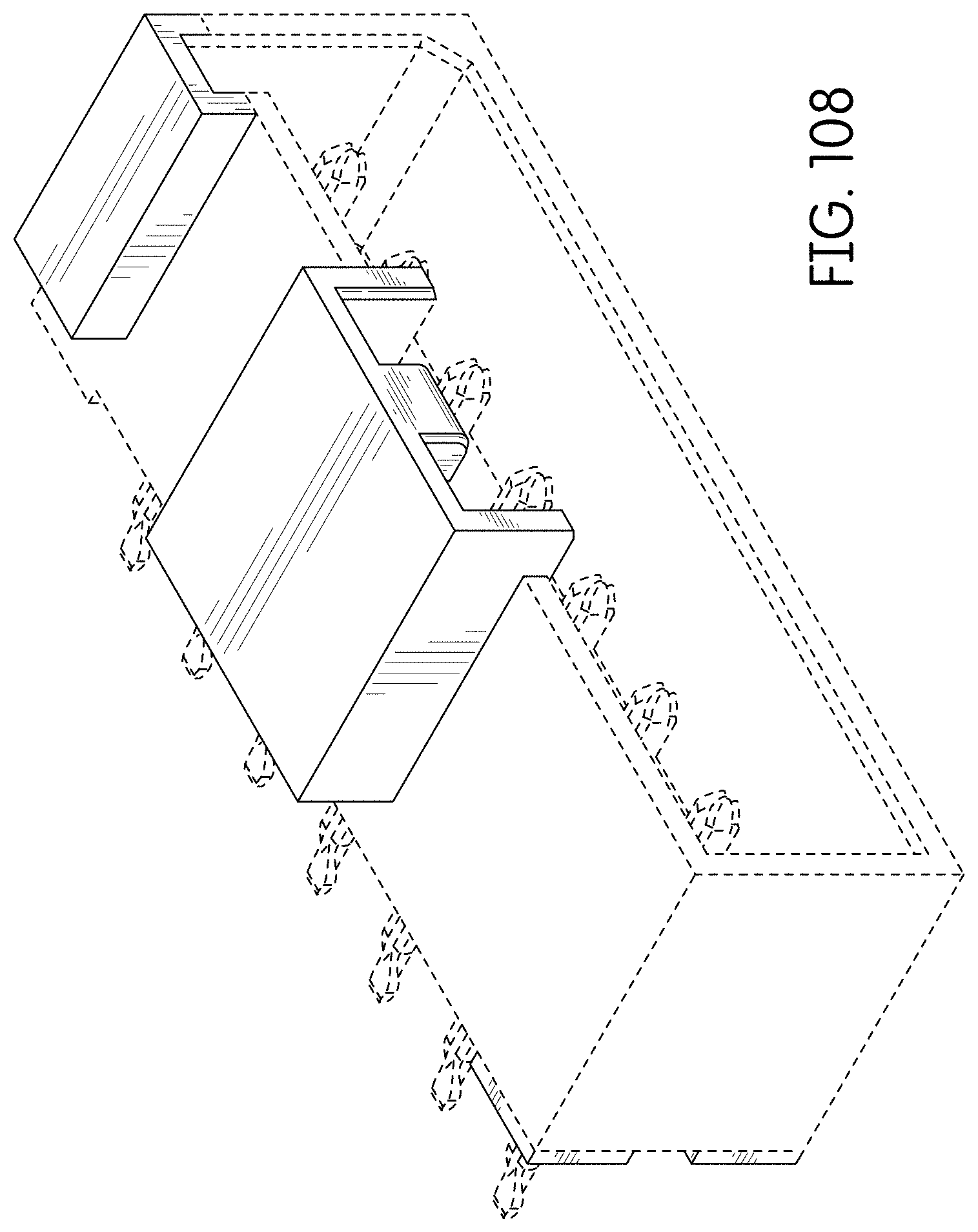
FIG. 108 is a rear perspective view thereof;
FIG. 109 is a front right perspective view of an alternate embodiment of the connector showing our new design;
FIG. 110 is a front left perspective view thereof;
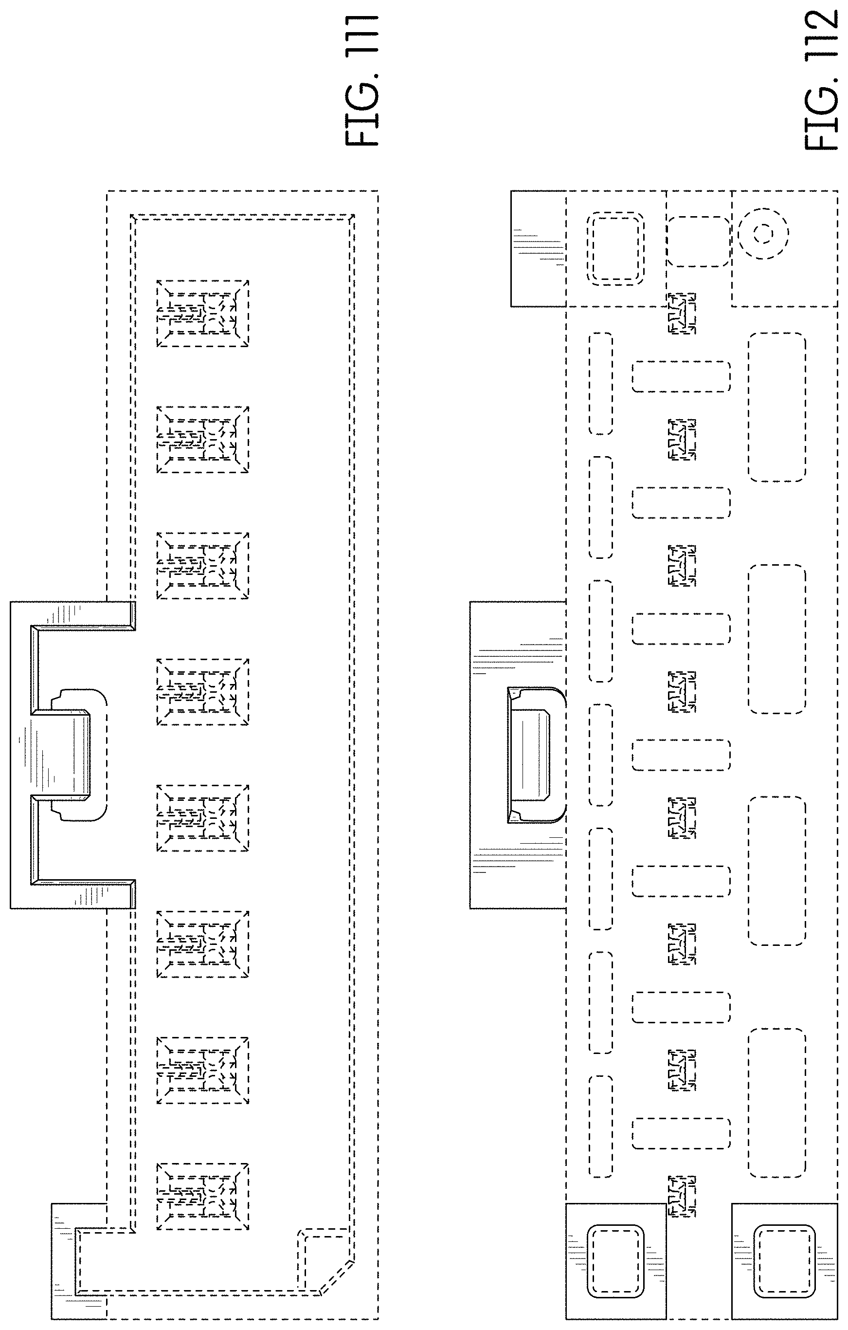
FIG. 111 is a rear view thereof;
FIG. 112 is a front view thereof;
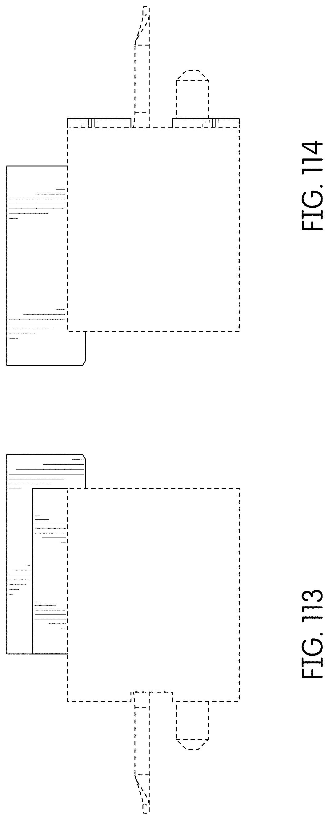
FIG. 113 is a right side view thereof;
FIG. 114 is a left side view thereof;
FIG. 115 is a top view thereof;
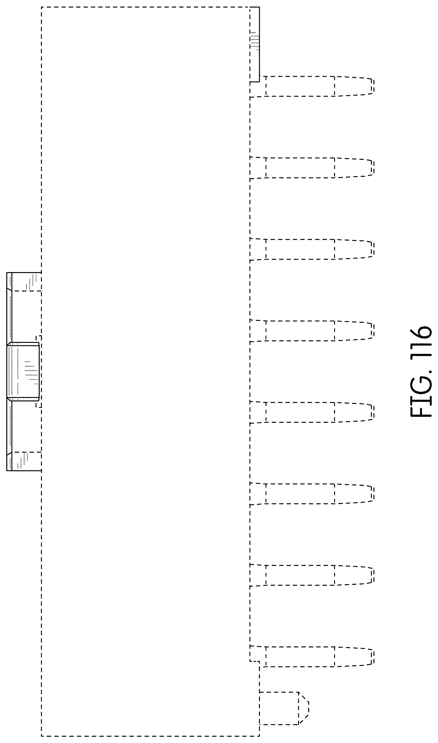
FIG. 116 is a bottom view thereof;
FIG. 117 is a rear perspective view thereof;
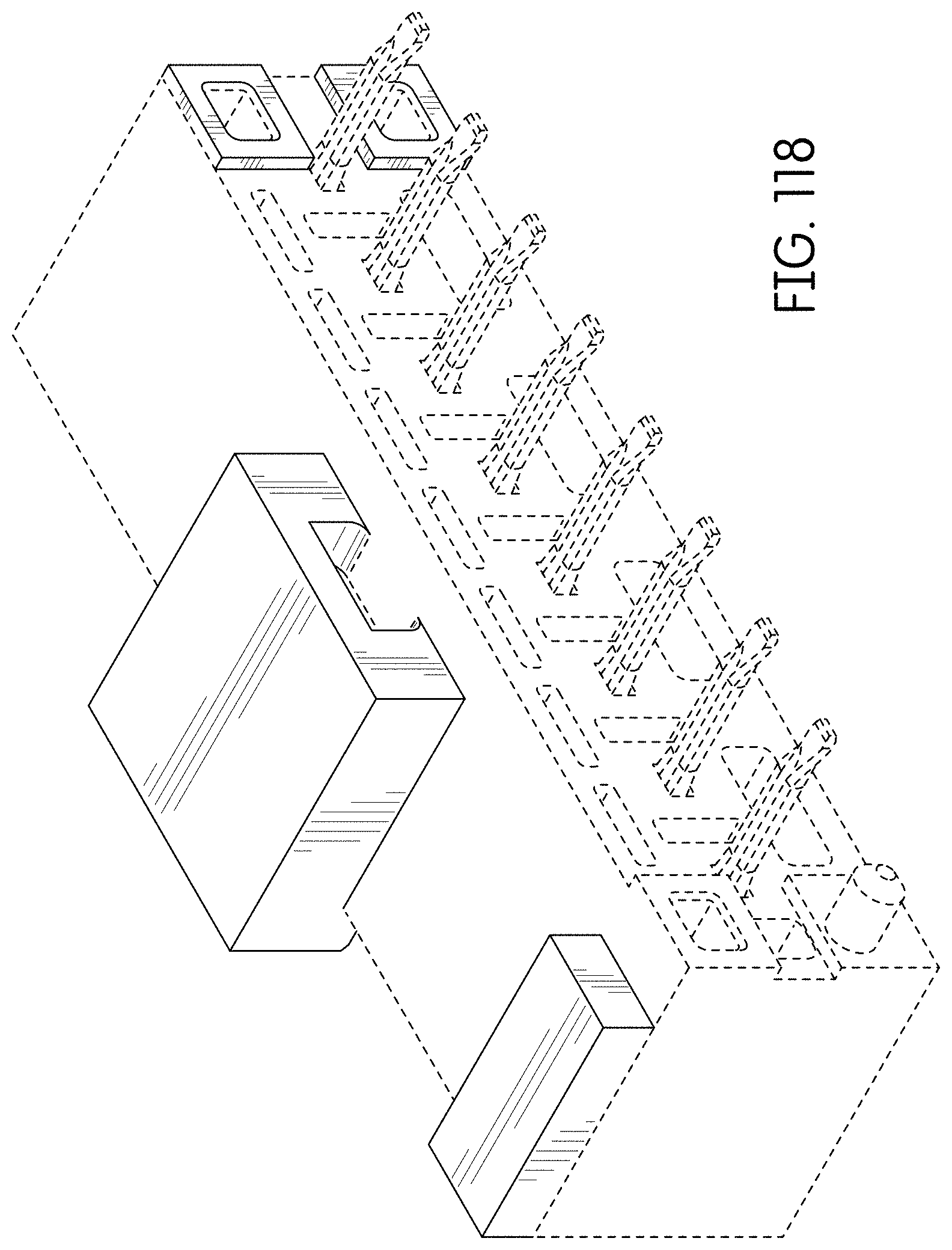
FIG. 118 is a front left perspective view of an alternate embodiment of the connector showing our new design which is a mirror image of the connector of FIGS. 109-117;
FIG. 119 is a front right perspective view thereof;
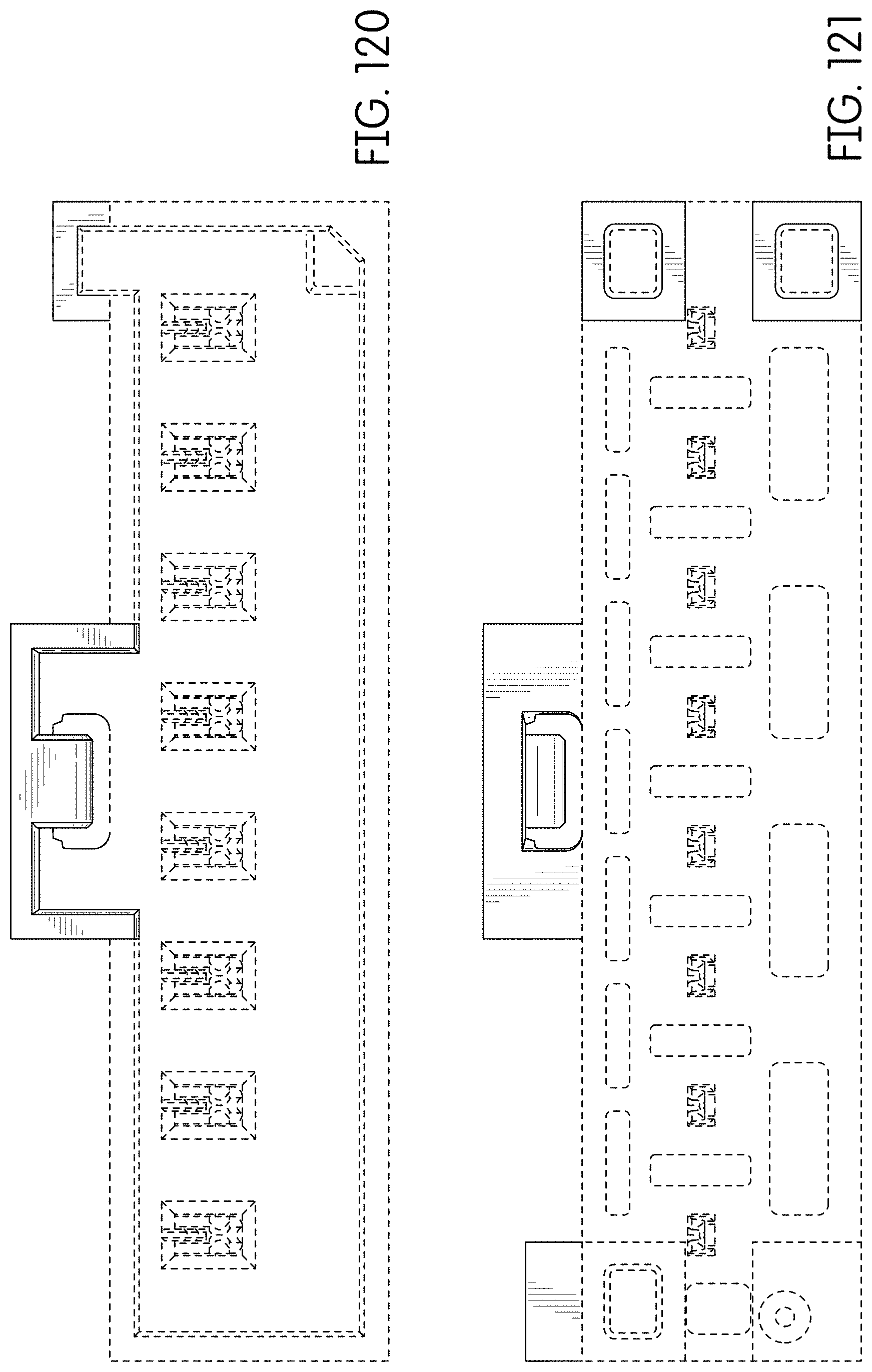
FIG. 120 is a rear view thereof;
FIG. 121 is a front view thereof;
FIG. 122 is a right side view thereof;
FIG. 123 is a left side view thereof;
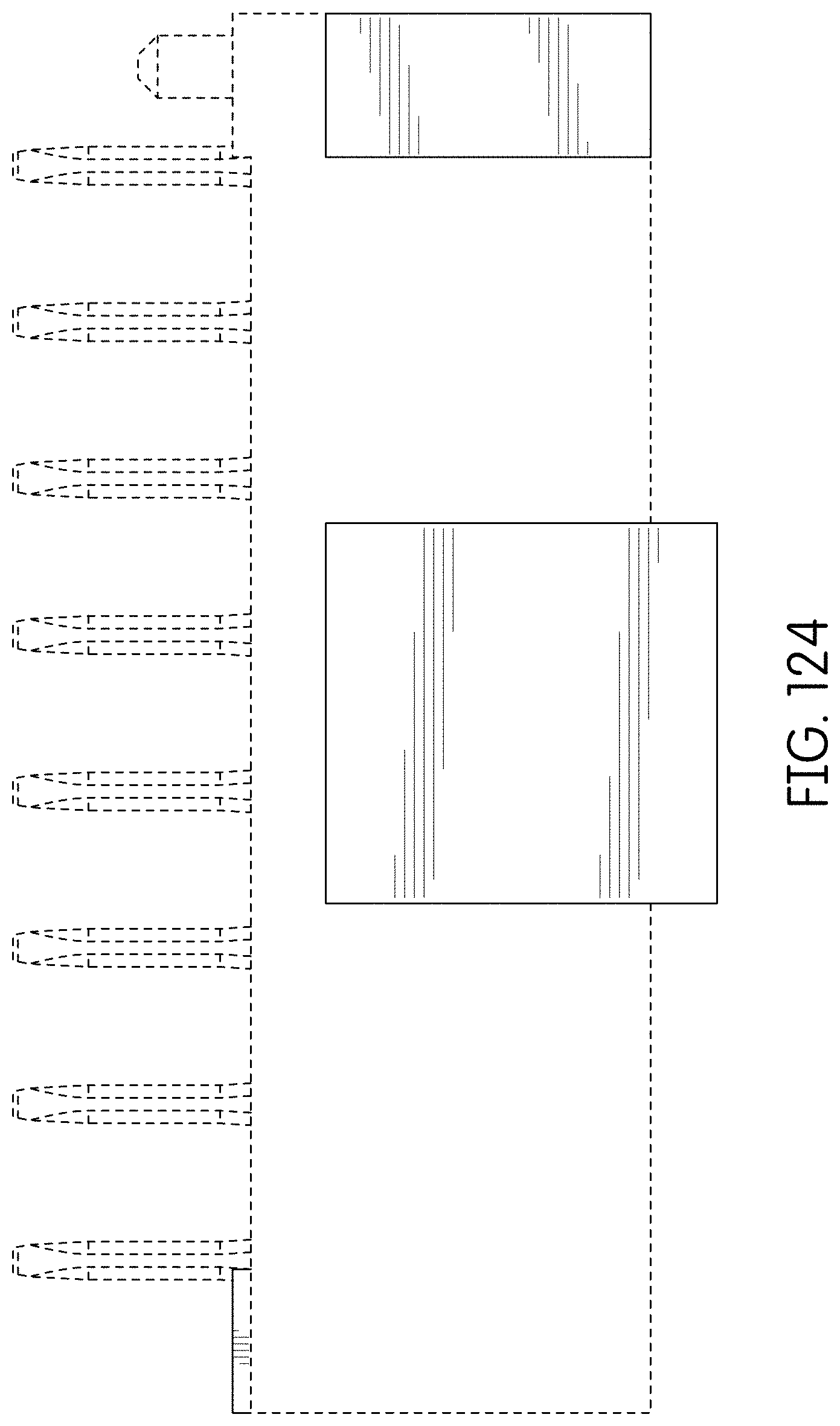
FIG. 124 is a top view thereof;
FIG. 125 is a bottom view thereof;
FIG. 126 is a rear perspective view thereof;
FIG. 127 is a front right perspective view of an alternate embodiment of the connector showing our new design;
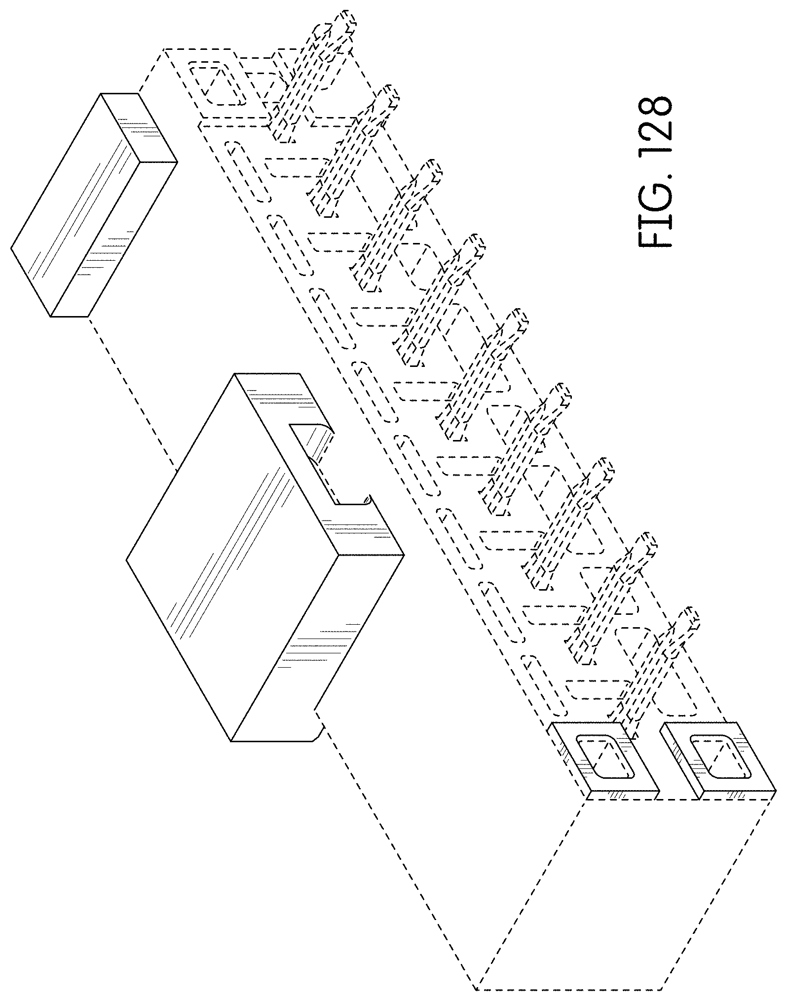
FIG. 128 is a front left perspective view thereof;
FIG. 129 is a rear view thereof;
FIG. 130 is a front view thereof;
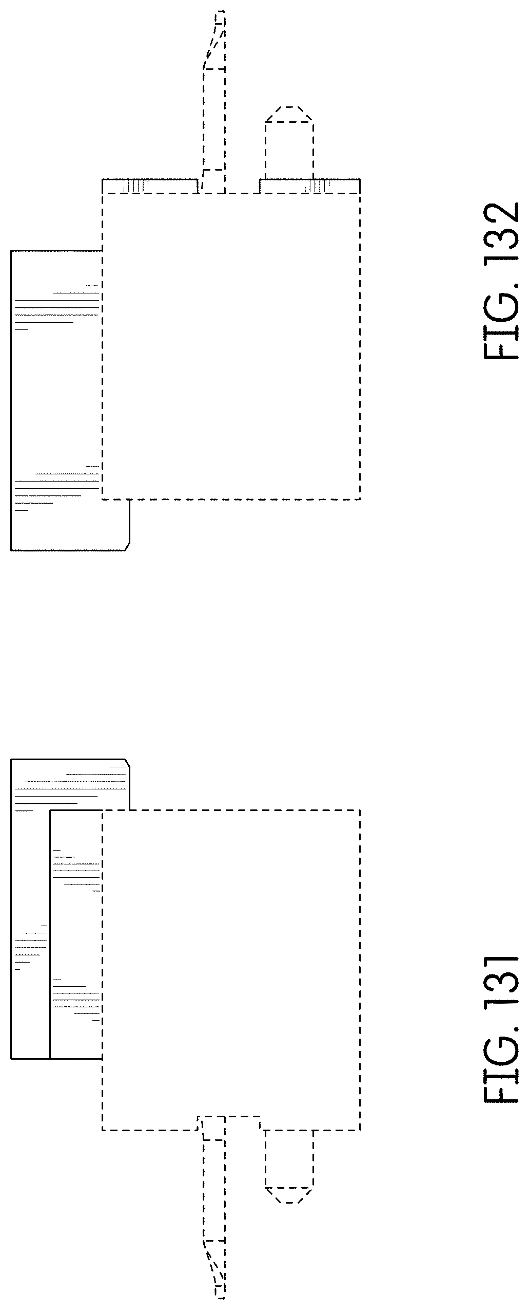
FIG. 131 is a right side view thereof;
FIG. 132 is a left side view thereof;
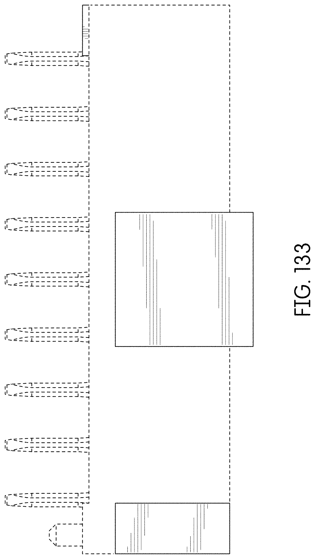
FIG. 133 is a top view thereof;
FIG. 134 is a bottom view thereof;
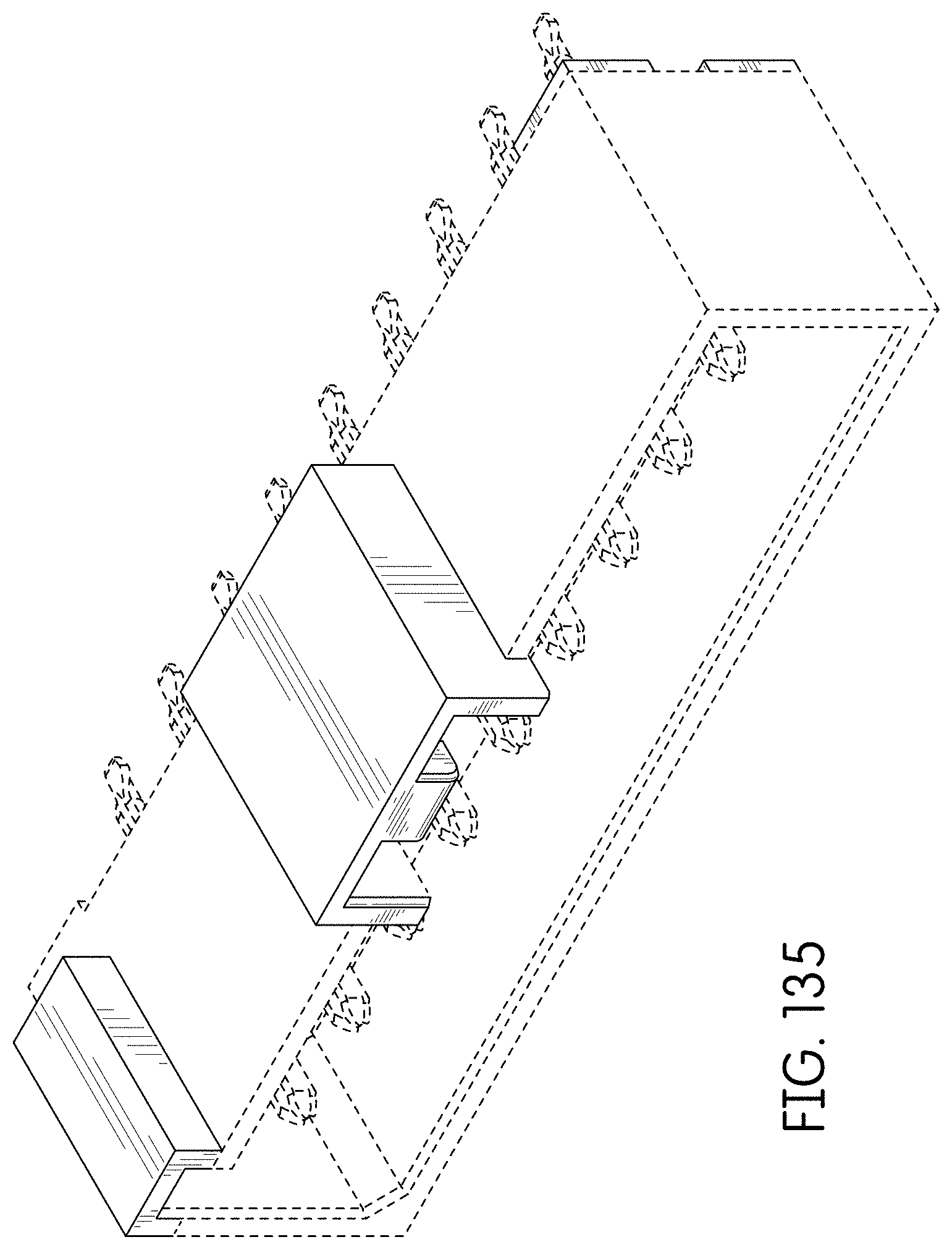
FIG. 135 is a rear perspective view thereof;
FIG. 136 is a front left perspective view of an alternate embodiment of the connector showing our new design which is a mirror image of the connector of FIGS. 127-135;
FIG. 137 is a front right perspective view thereof;
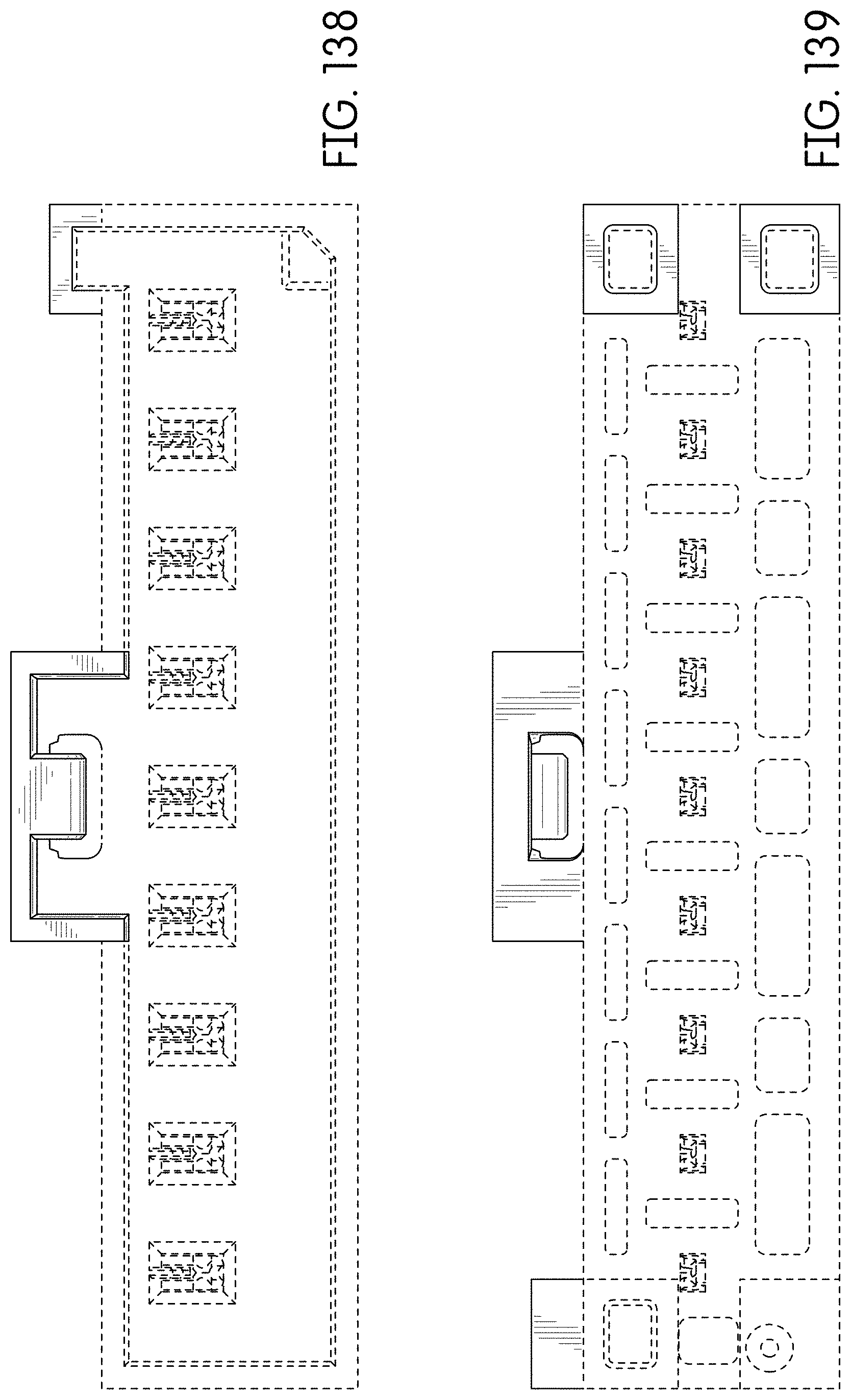
FIG. 138 is a rear view thereof;
FIG. 139 is a front view thereof;
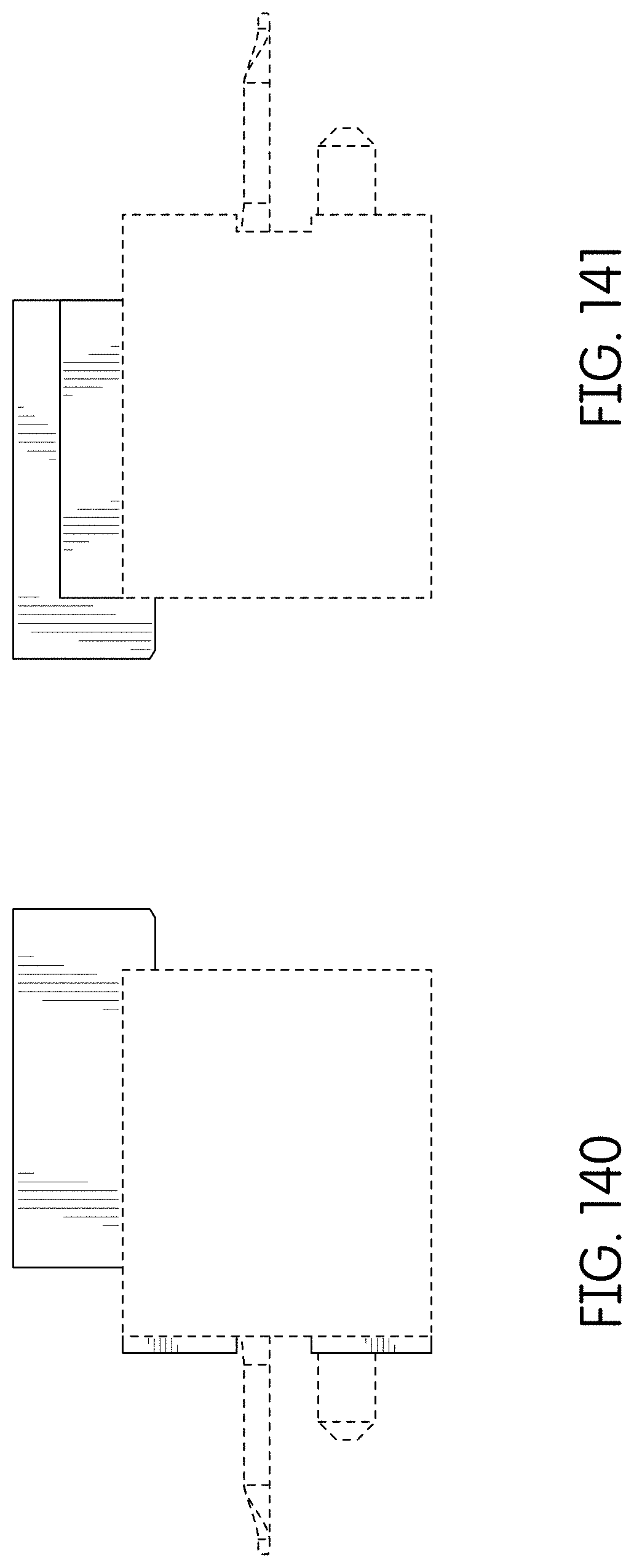
FIG. 140 is a right side view thereof;
FIG. 141 is a left side view thereof;
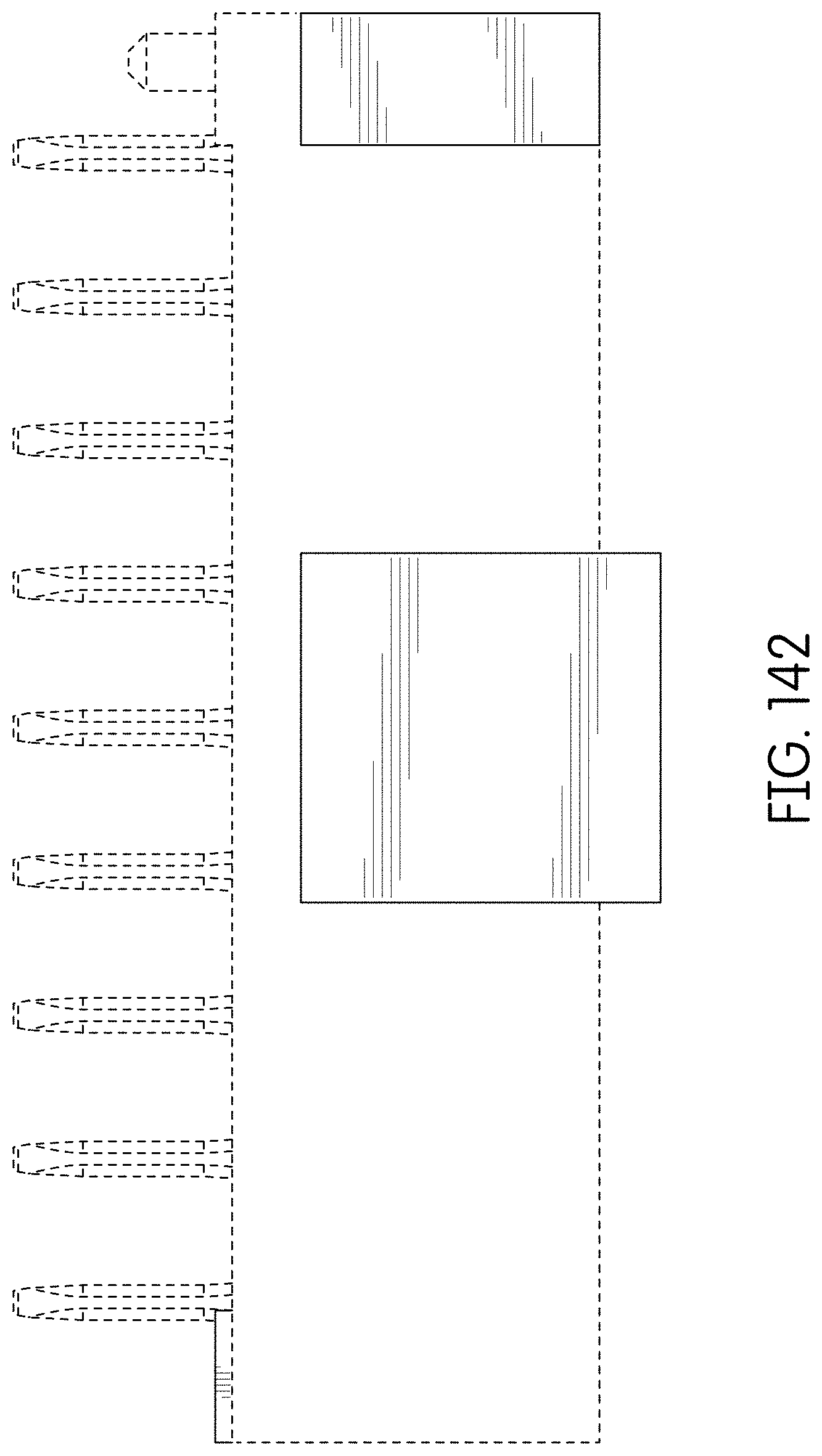
FIG. 142 is a top view thereof;
FIG. 143 is a bottom view thereof;
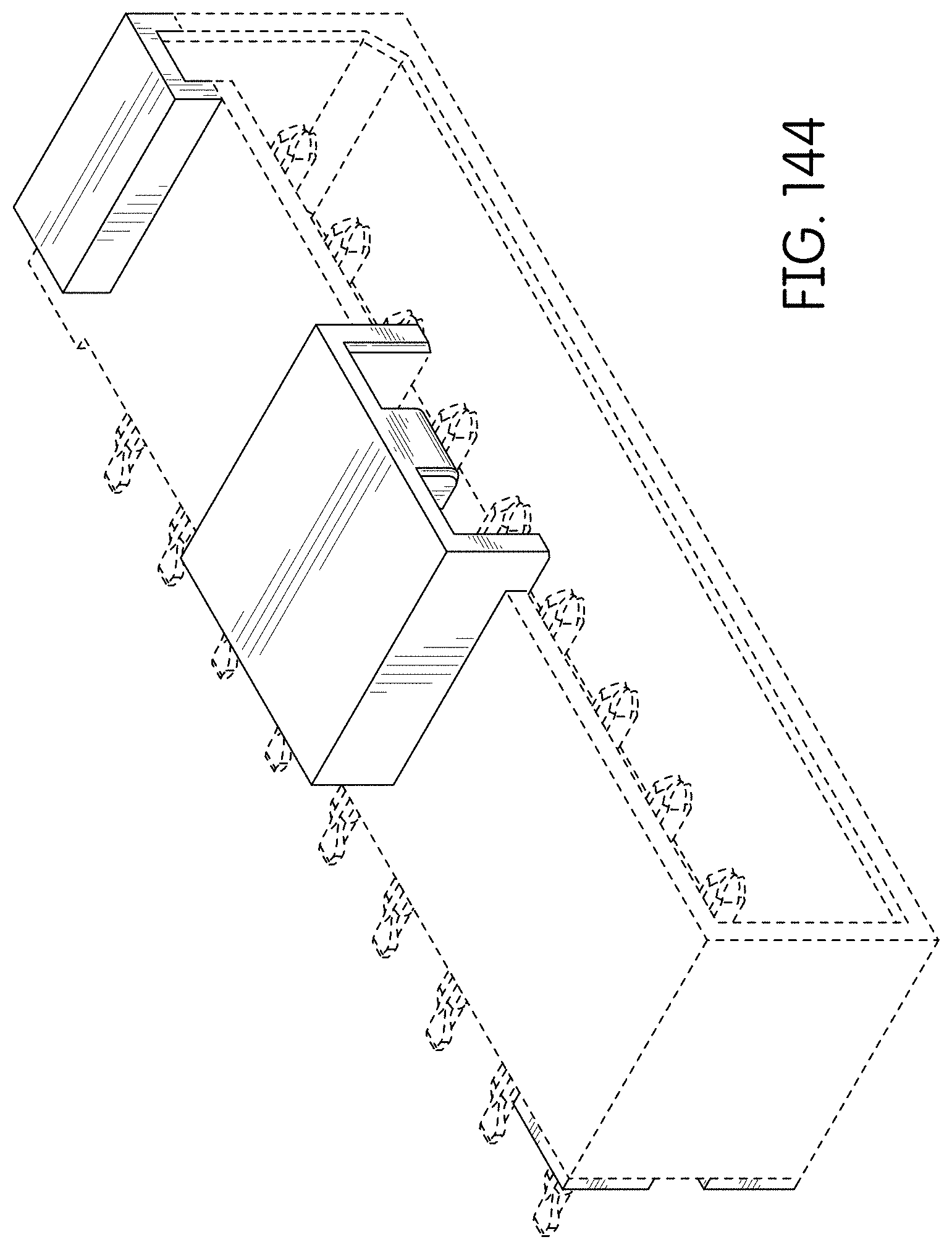
FIG. 144 is a rear perspective view thereof;
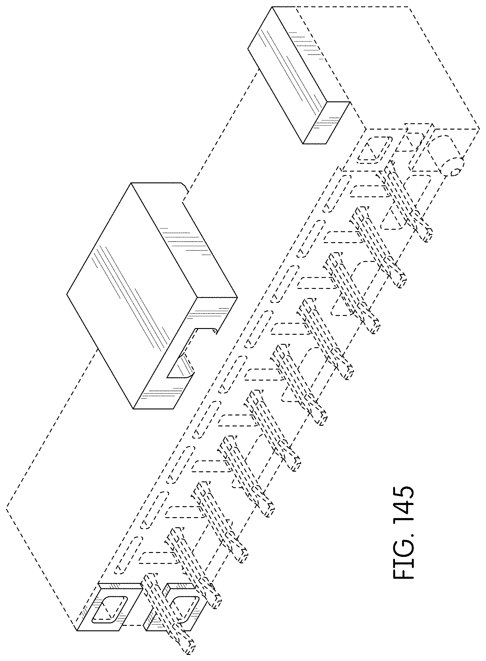
FIG. 145 is a front right perspective view of an alternate embodiment of the connector showing our new design;
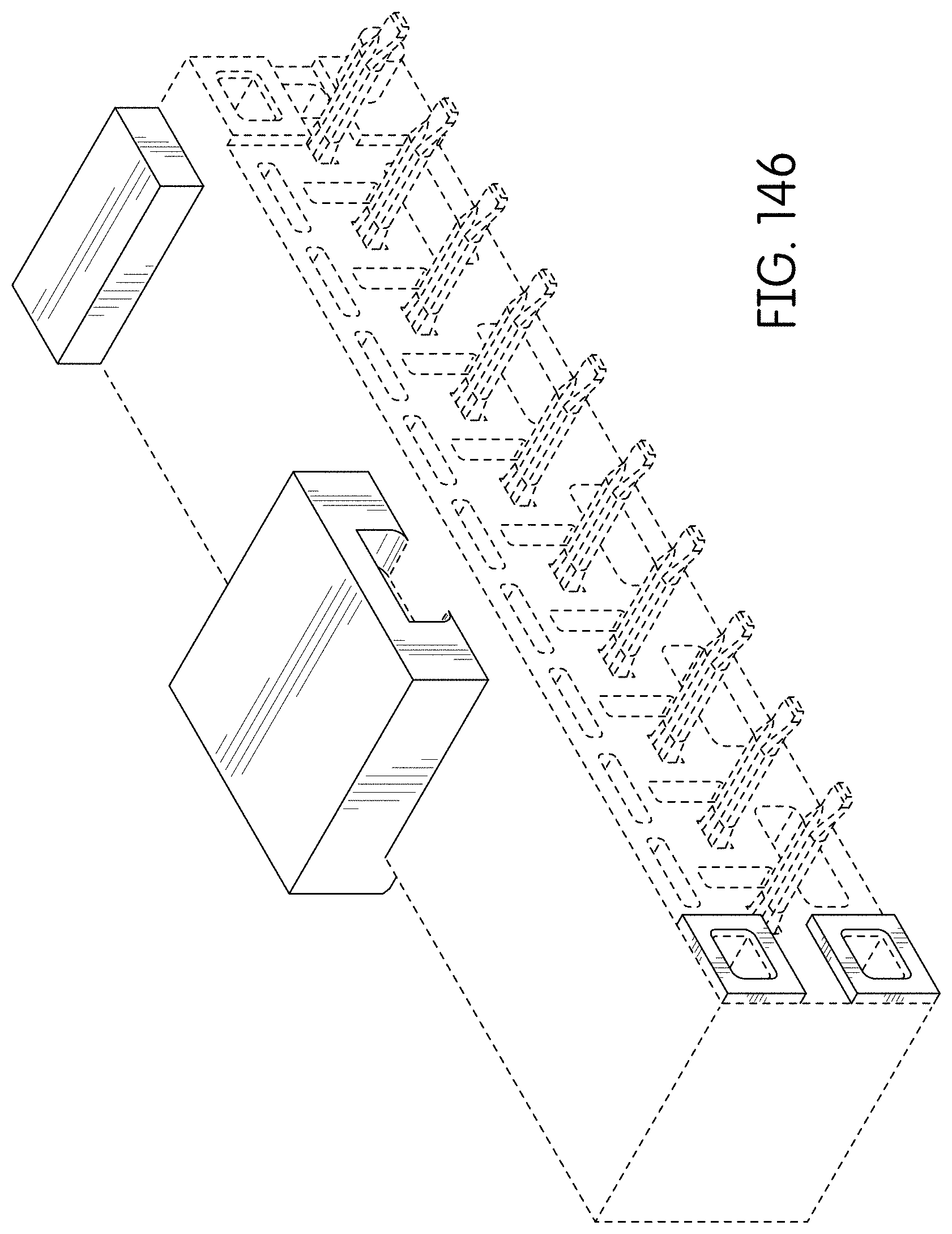
FIG. 146 is a front left perspective view thereof;
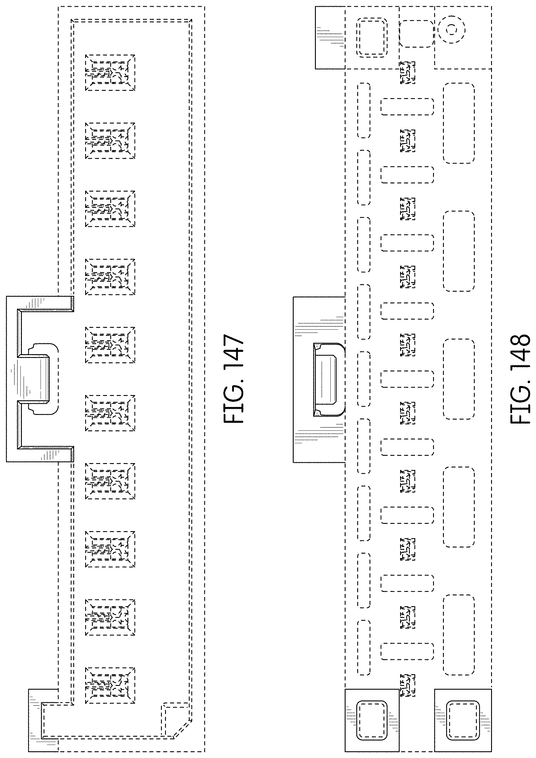
FIG. 147 is a rear view thereof;
FIG. 148 is a front view thereof;
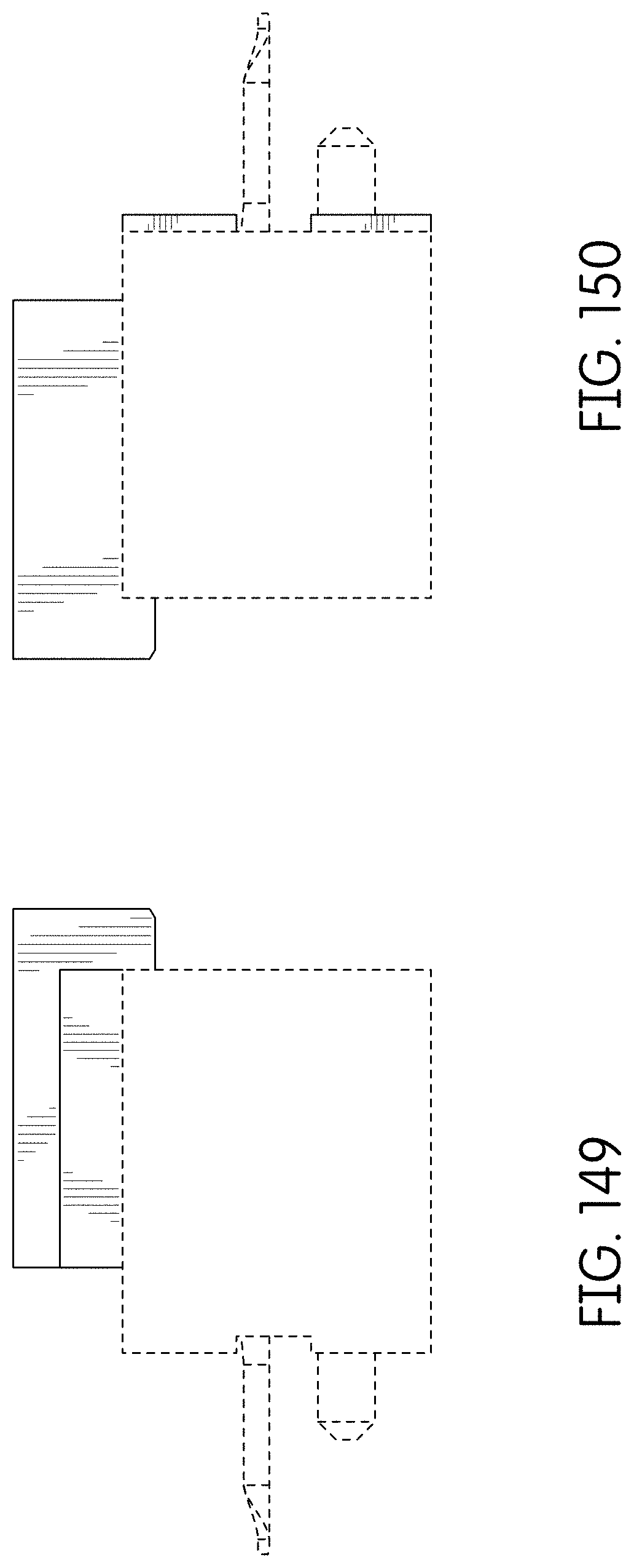
FIG. 149 is a right side view thereof;
FIG. 150 is a left side view thereof;
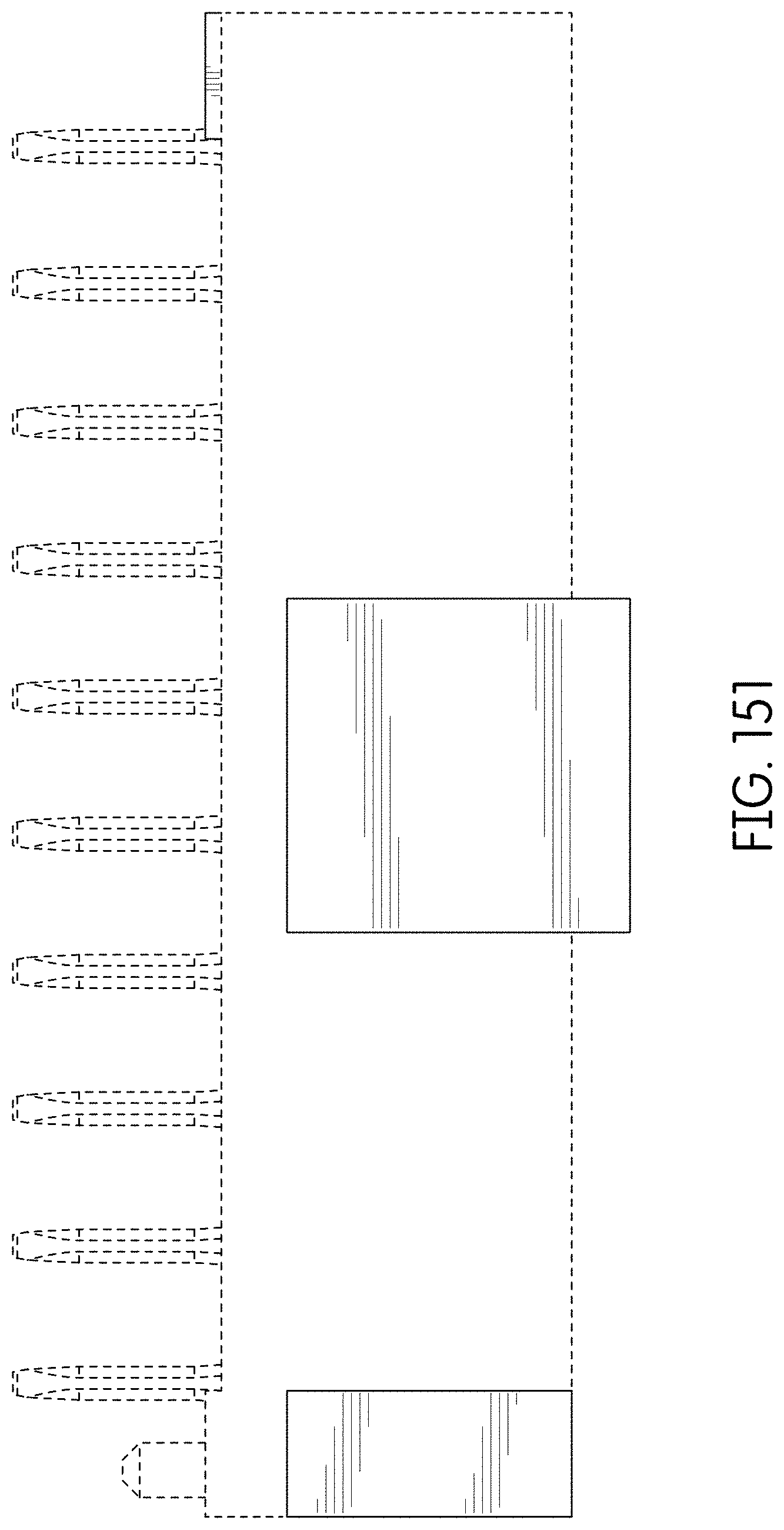
FIG. 151 is a top view thereof;
FIG. 152 is a bottom view thereof;
FIG. 153 is a rear perspective view thereof;
FIG. 154 is a front left perspective view of an alternate embodiment of the connector showing our new design which is a mirror image of the connector of FIGS. 145-153;
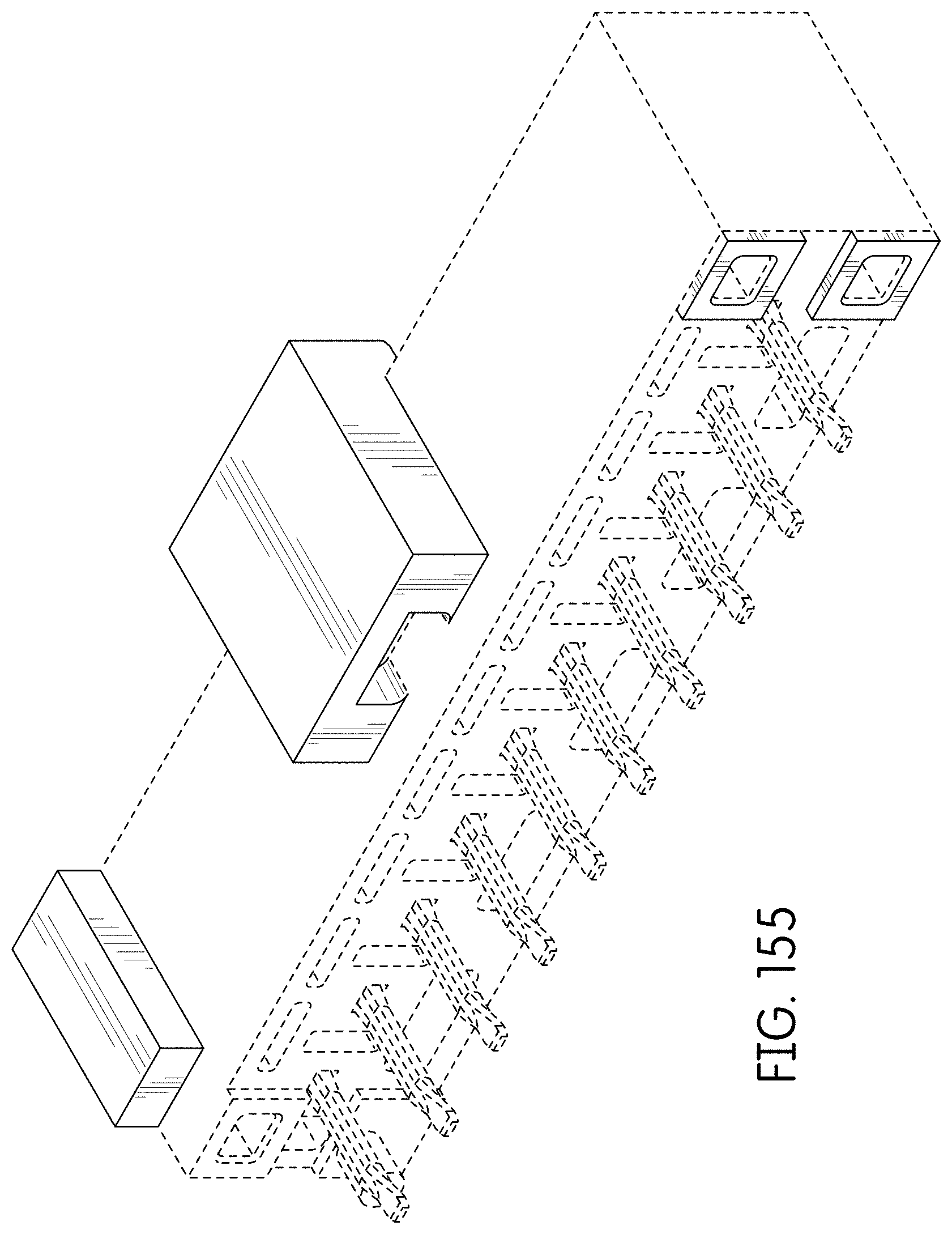
FIG. 155 is a front right perspective view thereof;
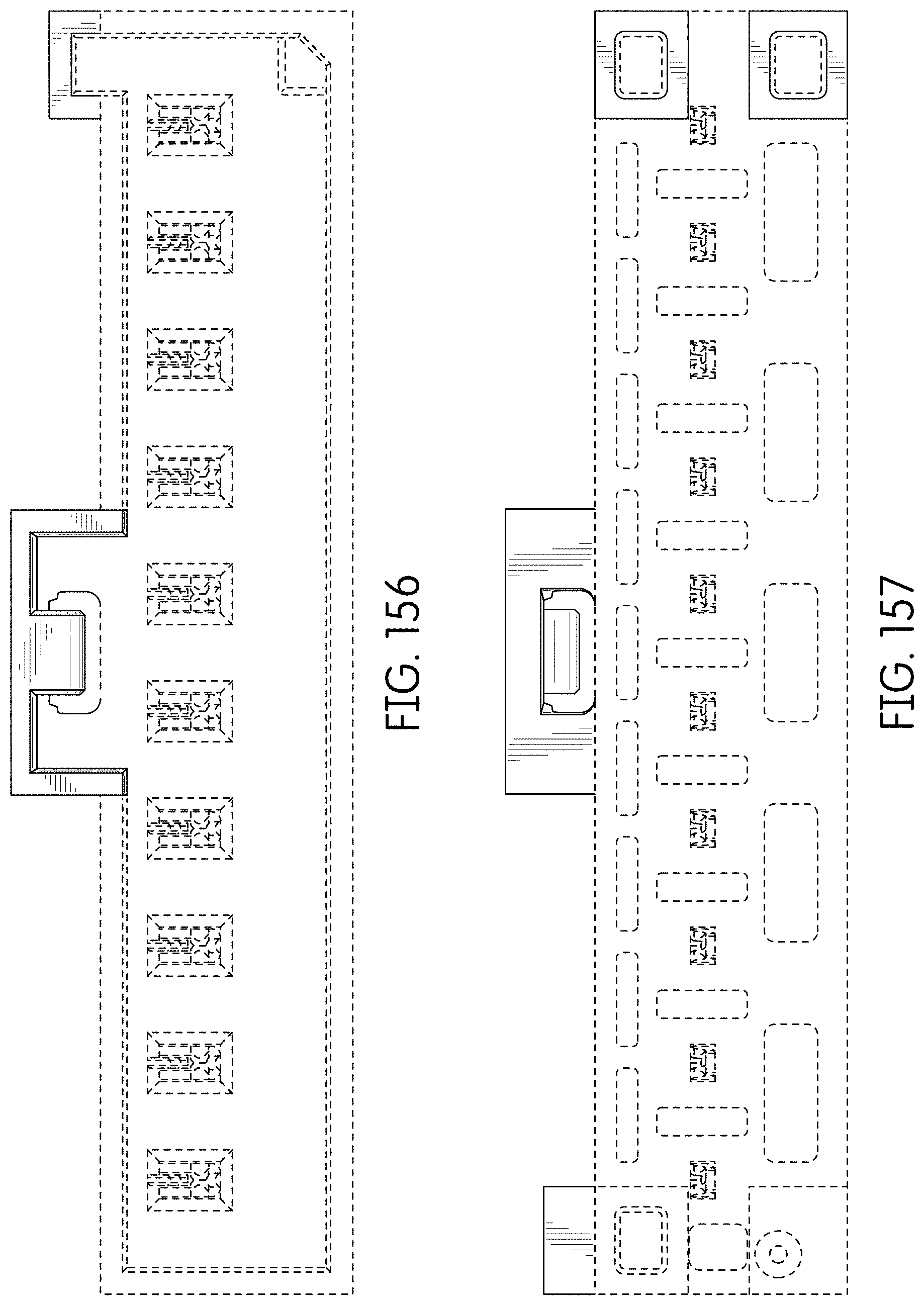
FIG. 156 is a rear view thereof;
FIG. 157 is a front view thereof;
FIG. 158 is a right side view thereof;
FIG. 159 is a left side view thereof;
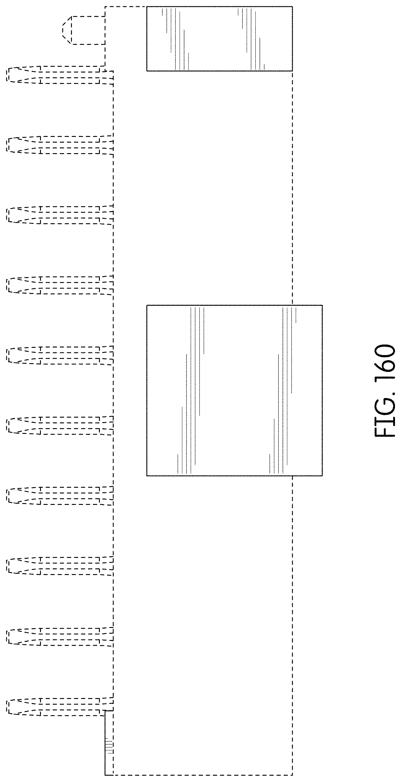
FIG. 160 is a top view thereof;
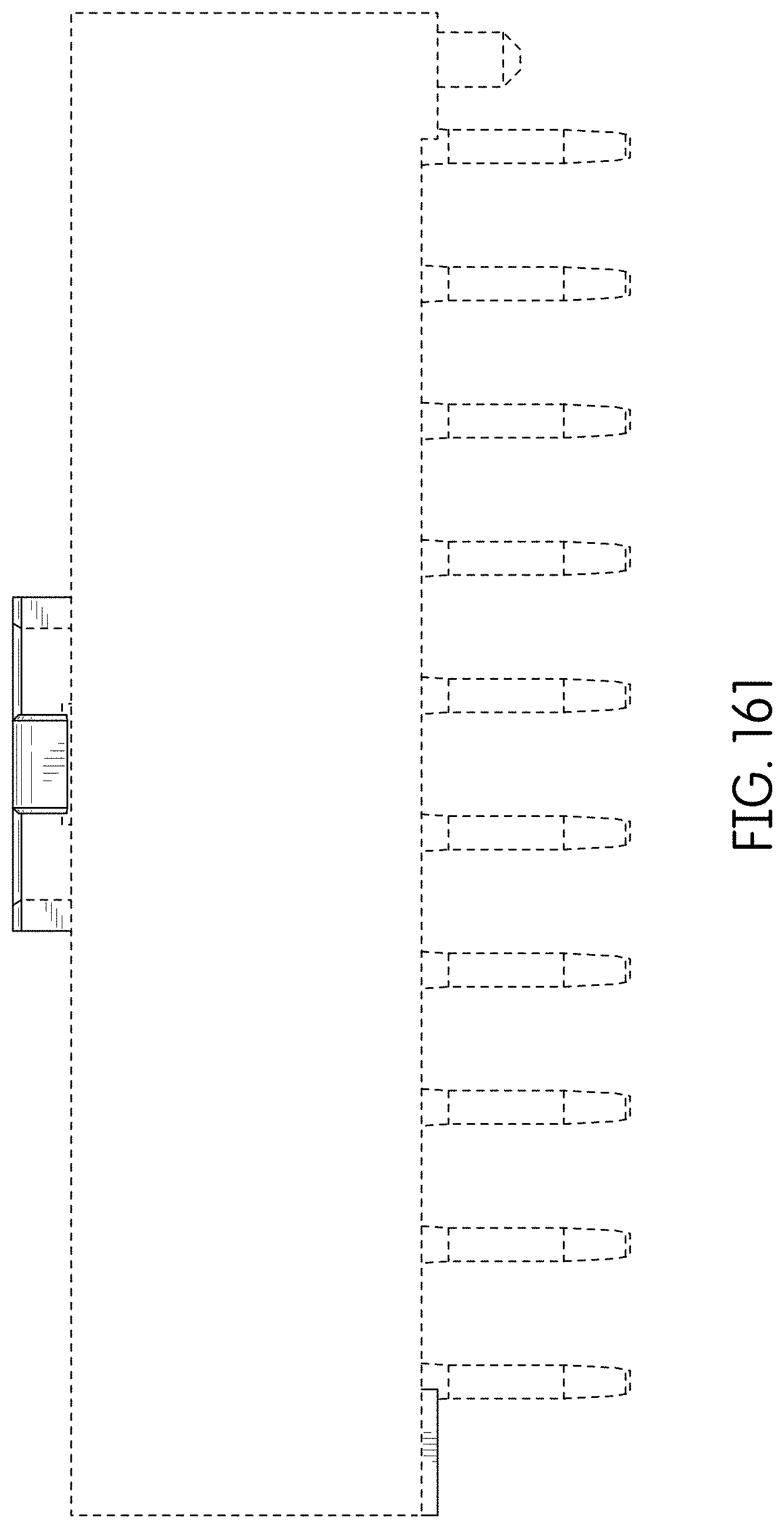
FIG. 161 is a bottom view thereof; and,
FIG. 162 is a rear perspective view thereof.
The broken lines immediately adjacent to the shaded areas depict the bounds of the claimed design and form no part thereof The broken lines depicting the remainder of the connector show features that form no part of the claimed design.
* * * * *
D00000
D00001
D00002
D00003
D00004
D00005
D00006
D00007
D00008
D00009
D00010
D00011
D00012
D00013

D00014
D00015

D00016
D00017
D00018
D00019
D00020

D00021
D00022
D00023
D00024
D00025
D00026
D00027

D00028

D00029
D00030

D00031

D00032
D00033

D00034

D00035

D00036

D00037
D00038

D00039
D00040
D00041

D00042

D00043
D00044

D00045
D00046
D00047

D00048

D00049
D00050

D00051

D00052

D00053
D00054
D00055

D00056
D00057
D00058

D00059
D00060

D00061

D00062
D00063

D00064

D00065
D00066

D00067
D00068
D00069
D00070

D00071
D00072
D00073

D00074

D00075
D00076
D00077

D00078
D00079

D00080
D00081

D00082
D00083

D00084
D00085

D00086

D00087

D00088
D00089

D00090
D00091
D00092

D00093
D00094

D00095

D00096
D00097
D00098
D00099

D00100
D00101
D00102
D00103
D00104
D00105
D00106

D00107

D00108

D00109
D00110
D00111

D00112
D00113
D00114

XML
uspto.report is an independent third-party trademark research tool that is not affiliated, endorsed, or sponsored by the United States Patent and Trademark Office (USPTO) or any other governmental organization. The information provided by uspto.report is based on publicly available data at the time of writing and is intended for informational purposes only.
While we strive to provide accurate and up-to-date information, we do not guarantee the accuracy, completeness, reliability, or suitability of the information displayed on this site. The use of this site is at your own risk. Any reliance you place on such information is therefore strictly at your own risk.
All official trademark data, including owner information, should be verified by visiting the official USPTO website at www.uspto.gov. This site is not intended to replace professional legal advice and should not be used as a substitute for consulting with a legal professional who is knowledgeable about trademark law.