Air intake system with a ribbed airbox
Niakan , et al. February 23, 2
U.S. patent number D911,393 [Application Number D/736,665] was granted by the patent office on 2021-02-23 for air intake system with a ribbed airbox. This patent grant is currently assigned to Advanced Flow Engineering, Inc.. The grantee listed for this patent is Advanced Flow Engineering, Inc.. Invention is credited to George R. Chiang, Shahriar Nick Niakan.


| United States Patent | D911,393 |
| Niakan , et al. | February 23, 2021 |
Air intake system with a ribbed airbox
Claims
CLAIM The ornamental design for an air intake system with a ribbed airbox, as shown and described.
| Inventors: | Niakan; Shahriar Nick (Corona, CA), Chiang; George R. (Corona, CA) | ||||||||||
|---|---|---|---|---|---|---|---|---|---|---|---|
| Applicant: |
|
||||||||||
| Assignee: | Advanced Flow Engineering, Inc.
(Corona, CA) |
||||||||||
| Appl. No.: | D/736,665 | ||||||||||
| Filed: | June 2, 2020 |
Related U.S. Patent Documents
| Application Number | Filing Date | Patent Number | Issue Date | ||
|---|---|---|---|---|---|
| 29656482 | Jul 12, 2018 | D886869 | |||
| Current U.S. Class: | D15/5 |
| Current International Class: | 1501 |
| Field of Search: | ;D15/1-6 |
References Cited [Referenced By]
U.S. Patent Documents
| D749134 | February 2016 | Niakan |
| D754208 | April 2016 | Niakan |
| D762247 | July 2016 | Niakan |
| D762735 | August 2016 | Niakan |
| D762736 | August 2016 | Niakan |
| D886867 | June 2020 | Niakan |
| D886868 | June 2020 | Niakan |
| 2005/0150483 | July 2005 | Sorensen |
| 2006/0196462 | September 2006 | Quezada |
| 2011/0067574 | March 2011 | Walz |
| 2012/0152632 | June 2012 | Azuma |
| 2013/0104832 | May 2013 | Chang |
| 2014/0116015 | May 2014 | Niakan |
| 2018/0216584 | August 2018 | Overgaard |
Other References
|
AFEPower 53-10007R QUANTUM Cold Air Intake System w/Pro 5R https://www.amazon.com/aFe-53-10007R/dp/B07H1KVBQM/ref=sr_1_84?dchild=1&k- eywords=aFe+Power+intake&qid=1601223668&sr=8-84 (Year: 2018). cited by examiner. |
Primary Examiner: Aman; Ania
Attorney, Agent or Firm: Crockett & Crockett, PC Crockett, Esq.; K. David Syrengelas, Esq.; Niky Economy
Description
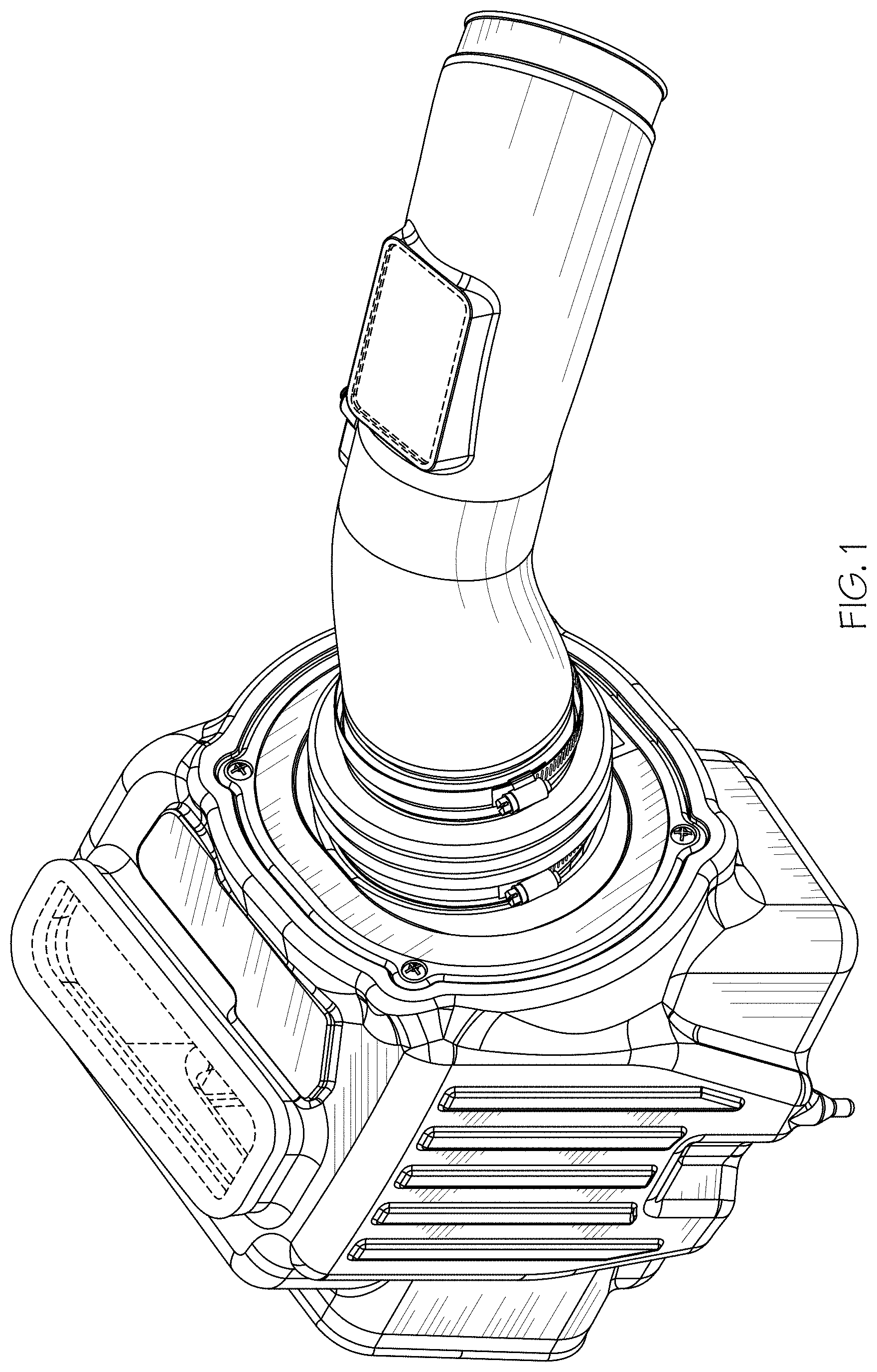
FIG. 1 is a left-front perspective view of an air intake system with a ribbed airbox showing our new design.
FIG. 2 is a front elevation view thereof.
FIG. 3 cross-section view of the air intake system of FIG. 2 taken along 3-3.
FIG. 4 is a left side elevation view thereof.
FIG. 5 is a right side elevation view thereof.
FIG. 6 is a rear elevation view thereof.
FIG. 7 is a top plan view thereof; and,
FIG. 8 is a bottom plan view thereof.
Broken lines in the attached drawings are included for the purpose of illustrating portions of the air intake system with a ribbed airbox and form no part of the claimed design.
* * * * *
References
D00000
D00001
D00002
D00003
D00004
D00005
D00006
D00007
D00008
XML
uspto.report is an independent third-party trademark research tool that is not affiliated, endorsed, or sponsored by the United States Patent and Trademark Office (USPTO) or any other governmental organization. The information provided by uspto.report is based on publicly available data at the time of writing and is intended for informational purposes only.
While we strive to provide accurate and up-to-date information, we do not guarantee the accuracy, completeness, reliability, or suitability of the information displayed on this site. The use of this site is at your own risk. Any reliance you place on such information is therefore strictly at your own risk.
All official trademark data, including owner information, should be verified by visiting the official USPTO website at www.uspto.gov. This site is not intended to replace professional legal advice and should not be used as a substitute for consulting with a legal professional who is knowledgeable about trademark law.