Computer pointing device
Cooper , et al. February 23, 2
U.S. patent number D911,338 [Application Number D/744,234] was granted by the patent office on 2021-02-23 for computer pointing device. This patent grant is currently assigned to The United States Government as represented by the Department of Veterans Affairs, University of Pittsburgh--Of The Commonwealth System of Higher Education. The grantee listed for this patent is The United States Goverment as represented by the Department of Veterans Affairs, The United States Goverment as represented by the Department of Veterans Affairs, University of Pittsburgh--Of The Commonwealth System of Higher Education. Invention is credited to Aaron Anderson, Zak Anzelone, Rory A. Cooper, Garrett Grindle.


| United States Patent | D911,338 |
| Cooper , et al. | February 23, 2021 |
Computer pointing device
Claims
CLAIM We claim the ornamental design for a computer pointing device, as shown and described.
| Inventors: | Cooper; Rory A. (Gibsonia, PA), Grindle; Garrett (Pittsburgh, PA), Anzelone; Zak (Blairsville, PA), Anderson; Aaron (Pittsburgh, PA) | ||||||||||
|---|---|---|---|---|---|---|---|---|---|---|---|
| Applicant: |
|
||||||||||
| Assignee: | The United States Government as
represented by the Department of Veterans Affairs (Washington,
DC) University of Pittsburgh--Of The Commonwealth System of Higher Education (Pittsburgh, PA) |
||||||||||
| Appl. No.: | D/744,234 | ||||||||||
| Filed: | July 28, 2020 |
Related U.S. Patent Documents
| Application Number | Filing Date | Patent Number | Issue Date | ||
|---|---|---|---|---|---|
| 29685637 | Mar 29, 2019 | D894899 | |||
| Current U.S. Class: | D14/402 |
| Current International Class: | 1402 |
| Field of Search: | ;D14/402-411,356,388,389,383-385,417,426 ;345/156-167 ;463/36-38 ;358/471,473 ;273/148B |
References Cited [Referenced By]
U.S. Patent Documents
| D288930 | March 1987 | Barbera |
| D328596 | August 1992 | Manabe |
| D338883 | August 1993 | Melzer |
| D357238 | April 1995 | Zirinsky |
| D359955 | July 1995 | Barrett |
| 6064370 | May 2000 | Wang |
| D427598 | July 2000 | Ciesko |
| D441362 | May 2001 | Sevougian |
| D442958 | May 2001 | Funakoshi |
| D495711 | September 2004 | Willat |
| D514105 | January 2006 | Ohta |
| D518050 | March 2006 | Wood |
| D801971 | November 2017 | Howell |
| D801972 | November 2017 | Howell |
| D890753 | July 2020 | Iasso |
| D894899 | September 2020 | Cooper |
Attorney, Agent or Firm: Ballard Spahr LLP
Description
FIG. 1 is an isometric view of an embodiment of our design for a computer pointing device;
FIG. 2 is a front view of the design of the computer pointing device shown in FIG. 1;
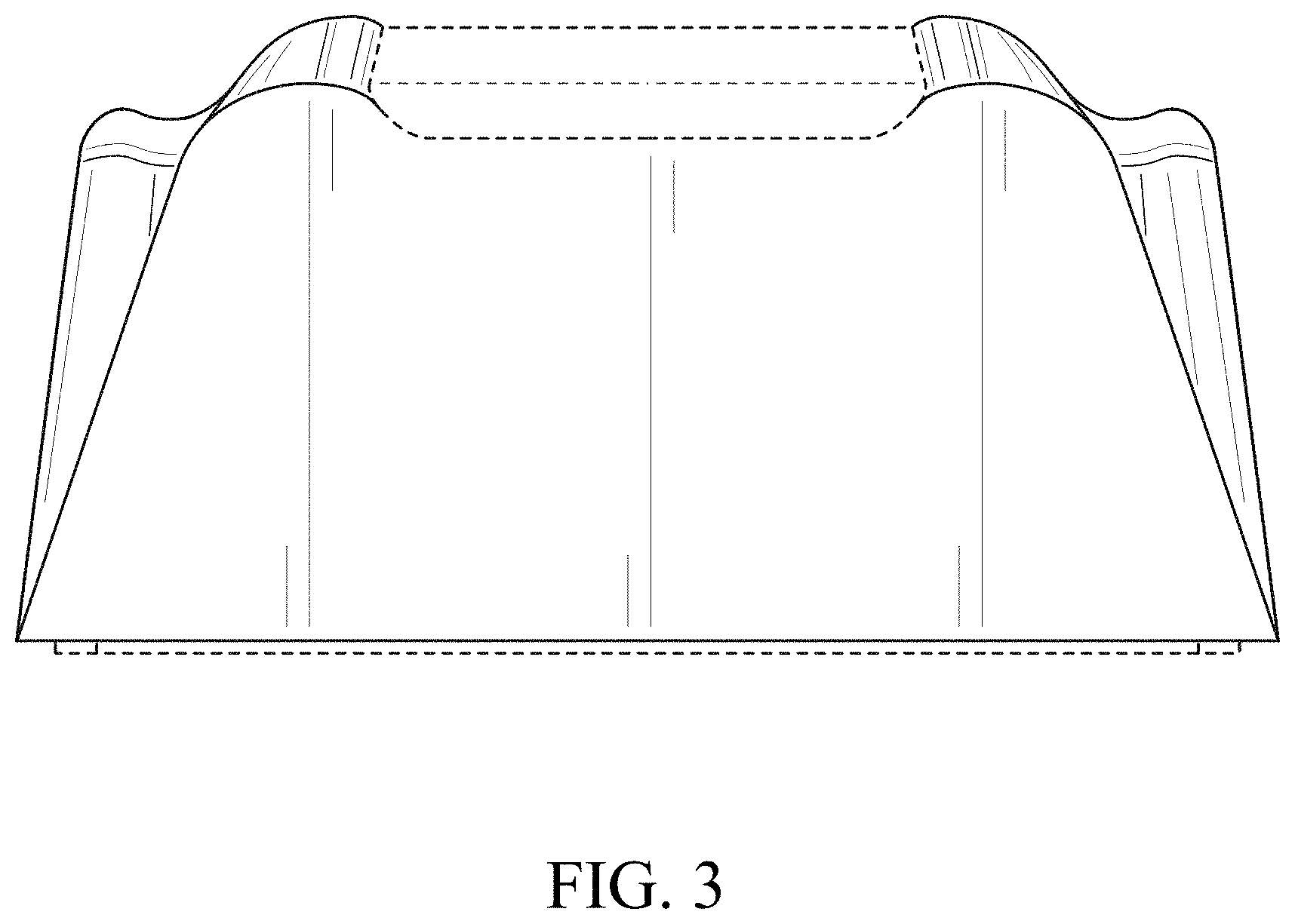
FIG. 3 is a rear view of the design of the computer pointing device shown in FIG. 1;
FIG. 4 is a right side view of the design of the computer pointing device shown in FIG. 1, the left side view being a mirror image thereof;
FIG. 5 is a top view of the design of the computer pointing device shown in FIG. 1; and,
FIG. 6 is a bottom view of the design of the computer pointing device shown in FIG. 1.
The broken lines depict portions of the computer pointing device that form no part of the claimed design.
* * * * *
D00000
D00001
D00002
D00003
D00004
D00005
D00006
XML
uspto.report is an independent third-party trademark research tool that is not affiliated, endorsed, or sponsored by the United States Patent and Trademark Office (USPTO) or any other governmental organization. The information provided by uspto.report is based on publicly available data at the time of writing and is intended for informational purposes only.
While we strive to provide accurate and up-to-date information, we do not guarantee the accuracy, completeness, reliability, or suitability of the information displayed on this site. The use of this site is at your own risk. Any reliance you place on such information is therefore strictly at your own risk.
All official trademark data, including owner information, should be verified by visiting the official USPTO website at www.uspto.gov. This site is not intended to replace professional legal advice and should not be used as a substitute for consulting with a legal professional who is knowledgeable about trademark law.