Screwdriver
Hyma , et al. February 23, 2
U.S. patent number D911,140 [Application Number D/693,863] was granted by the patent office on 2021-02-23 for screwdriver. This patent grant is currently assigned to Milwaukee Electric Tool Corporation. The grantee listed for this patent is Milwaukee Electric Tool Corporation. Invention is credited to Kyle C. Anderson, Aaron S. Blumenthal, Mark W. Cors, Joseph M. DeBaker, Christopher S. Hoppe, Steven W. Hyma.


View All Diagrams
| United States Patent | D911,140 |
| Hyma , et al. | February 23, 2021 |
Screwdriver
Claims
CLAIM We claim the ornamental design for a screwdriver, as shown and described.
| Inventors: | Hyma; Steven W. (Milwaukee, WI), DeBaker; Joseph M. (Greenfield, WI), Anderson; Kyle C. (Milwaukee, WI), Blumenthal; Aaron S. (Wauwatosa, WI), Cors; Mark W. (St. Francis, WI), Hoppe; Christopher S. (Milwaukee, WI) | ||||||||||
|---|---|---|---|---|---|---|---|---|---|---|---|
| Applicant: |
|
||||||||||
| Assignee: | Milwaukee Electric Tool
Corporation (Brookfield, WI) |
||||||||||
| Appl. No.: | D/693,863 | ||||||||||
| Filed: | June 5, 2019 |
Related U.S. Patent Documents
| Application Number | Filing Date | Patent Number | Issue Date | ||
|---|---|---|---|---|---|
| 29613327 | Aug 9, 2017 | D855433 | |||
| Current U.S. Class: | D8/82 |
| Current International Class: | 0804 |
| Field of Search: | ;D8/82,83,84,85,86,87,107,303 ;D7/395 ;D4/138 ;D24/133 |
References Cited [Referenced By]
U.S. Patent Documents
| 1541078 | June 1925 | Sudweeks |
| 1738405 | December 1929 | Thal |
| 1741349 | December 1929 | Sullivan |
| 1782981 | November 1930 | Anderson |
| 1899489 | February 1933 | Wickbergh |
| 3133568 | May 1964 | Reed |
| 3211199 | October 1965 | Reed |
| 3393722 | July 1968 | Windham |
| 3616827 | November 1971 | Stillwagon, Jr. |
| 3656522 | April 1972 | Ingimarsson |
| 4404749 | September 1983 | Emerson |
| 4778730 | October 1988 | Z:Ucker |
| 4998454 | March 1991 | Chaconas et al. |
| 5025688 | June 1991 | Davis |
| 5237893 | August 1993 | Ryder et al. |
| D340633 | October 1993 | Badiali |
| 5259277 | November 1993 | Zurbuchen |
| 5259279 | November 1993 | Strauch |
| 5259280 | November 1993 | Hoy |
| 5284075 | February 1994 | Strauch et al. |
| 5291811 | March 1994 | Goss |
| 5341707 | August 1994 | Bond |
| 5421224 | June 1995 | Bond |
| D360344 | July 1995 | Eggert et al. |
| 5461952 | October 1995 | Goss |
| D375669 | November 1996 | Shiao |
| D378186 | February 1997 | Braun |
| 5601003 | February 1997 | Amtenbrink et al. |
| D379750 | June 1997 | Thompson et al. |
| D383660 | September 1997 | Anderson |
| D393582 | April 1998 | Amtenbrink et al. |
| D398507 | September 1998 | Thompson et al. |
| D398508 | September 1998 | Thompson et al. |
| D402179 | December 1998 | Scott |
| 5868047 | February 1999 | Faust et al. |
| D408253 | April 1999 | Rowlay |
| D411428 | June 1999 | Scott |
| D414095 | September 1999 | Hoepfl et al. |
| D415007 | October 1999 | Jimenez et al. |
| 5964009 | October 1999 | Hoepfl et al. |
| 6019022 | February 2000 | Dotson |
| D427877 | July 2000 | Rowlay et al. |
| 6228306 | May 2001 | Hoepfl et al. |
| D447678 | September 2001 | Staton et al. |
| 6295903 | October 2001 | Tipper et al. |
| 6368536 | April 2002 | Hoepfl et al. |
| 6397710 | June 2002 | Baker |
| D467486 | December 2002 | Mathieu et al. |
| D468182 | January 2003 | Thompson et al. |
| 6520055 | February 2003 | Reusch et al. |
| D481290 | October 2003 | Thompson et al. |
| D487690 | March 2004 | Hu |
| 6883405 | April 2005 | Strauch |
| D523315 | June 2006 | Kienzler |
| 7065883 | June 2006 | Popeil et al. |
| D542620 | May 2007 | Thompson et al. |
| D553464 | October 2007 | Rinner |
| 7325469 | February 2008 | Clampitt, Jr. et al. |
| 7395602 | July 2008 | Backus et al. |
| D575132 | August 2008 | Panier |
| 7814815 | October 2010 | Chen |
| RE42278 | April 2011 | Kienzler |
| 8136430 | March 2012 | Hu |
| 8166851 | May 2012 | Pchola et al. |
| D682067 | May 2013 | Tillet |
| D691015 | October 2013 | Hyma et al. |
| D694608 | December 2013 | Nelson et al. |
| 8701524 | April 2014 | Chang et al. |
| 8870078 | October 2014 | Webb et al. |
| D716629 | November 2014 | Suter |
| 8973474 | March 2015 | Lai |
| D753978 | April 2016 | Ranieri |
| 9314907 | April 2016 | Wang |
| D774867 | December 2016 | Panier |
| D778703 | February 2017 | Nelson |
| D800528 | October 2017 | Leibowitz |
| D829524 | October 2018 | Su |
| D840207 | February 2019 | Sun |
| 2004/0006876 | January 2004 | Popeil et al. |
| 2004/0099106 | May 2004 | Strauch et al. |
| 2004/0200079 | October 2004 | Stoughton et al. |
| 2005/0076749 | April 2005 | Liu |
| 2007/0051215 | March 2007 | Petillo |
| 2008/0066589 | March 2008 | Tseng |
| 2008/0127473 | June 2008 | Yu |
| 2008/0265594 | October 2008 | Popeil et al. |
| 2008/0276770 | November 2008 | Blum et al. |
| 2009/0165604 | July 2009 | Macor |
| 2010/0288086 | November 2010 | Huang |
| 2012/0285301 | November 2012 | Totsu |
| 2014/0325816 | November 2014 | Ng et al. |
| 2016/0129581 | May 2016 | Lee et al. |
| 2209023 | Oct 1995 | CN | |||
| 3126913 | Nov 1999 | CN | |||
| 201544179 | Aug 2010 | CN | |||
| 202399186 | Aug 2012 | CN | |||
| 103737529 | Apr 2014 | CN | |||
| 303336007 | Aug 2015 | CN | |||
| 105291018 | Feb 2016 | CN | |||
| 205703936 | Nov 2016 | CN | |||
| 8519877 | Oct 1985 | DE | |||
| 8515835 | Oct 1986 | DE | |||
| 4029734 | Mar 1992 | DE | |||
| 9303706 | May 1993 | DE | |||
| 9400780 | Mar 1994 | DE | |||
| 29703215 | Jun 1998 | DE | |||
| 29820168 | Jan 1999 | DE | |||
| 19720139 | Mar 1999 | DE | |||
| 20017964 | Feb 2002 | DE | |||
| 20203297 | Jul 2002 | DE | |||
| 0316555 | Feb 2003 | DE | |||
| 10234205 | Feb 2003 | DE | |||
| 20117855 | Mar 2003 | DE | |||
| 10204570 | Sep 2003 | DE | |||
| 10209034 | Sep 2003 | DE | |||
| 2011051984 | Nov 2011 | DE | |||
| 202012102262 | Jul 2012 | DE | |||
| 608711 | Aug 1994 | EP | |||
| 1422027 | May 2004 | EP | |||
| 685851 | Jul 1930 | FR | |||
| 1325282 | Apr 1963 | FR | |||
| 1396783 | Apr 1965 | FR | |||
| 342438 | Feb 1931 | GB | |||
| 1296731 | Nov 1972 | GB | |||
| 2063743 | Jun 1981 | GB | |||
| 2321868 | Aug 1998 | GB | |||
| 7407268 | Dec 1975 | NL | |||
| 551876 | Sep 2003 | TW | |||
| D103108 | Feb 2005 | TW | |||
| D111513 | Jun 2006 | TW | |||
| M367782 | Nov 2009 | TW | |||
| M468385 | Dec 2013 | TW | |||
| WO9004498 | May 1990 | WO | |||
| WO9414576 | Jul 1994 | WO | |||
| WO2010040878 | Apr 2010 | WO | |||
Attorney, Agent or Firm: Reinhart Boerner Van Deuren s.c.
Description
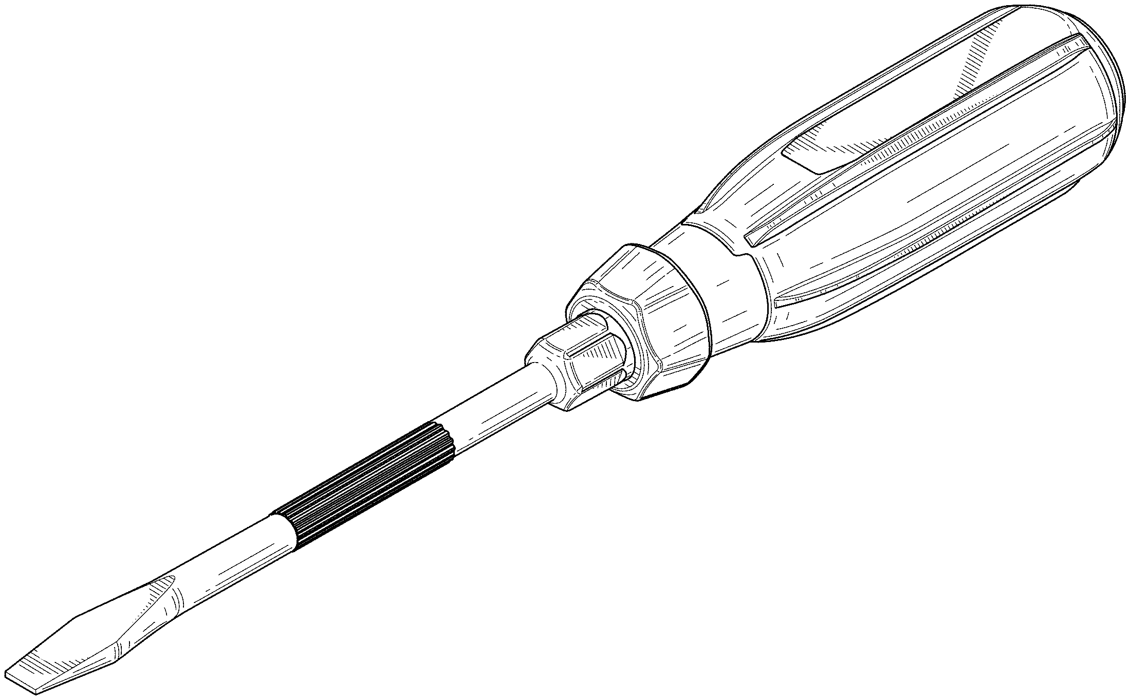
FIG. 1 is a perspective view of a first embodiment of a screwdriver, showing the new design.
FIG. 2 is a first side view of the screwdriver of FIG. 1.
FIG. 3 is a second side view of the screwdriver of FIG. 1.
FIG. 4 is a front side view of the screwdriver of FIG. 1.
FIG. 5 is a back side view of the screwdriver of FIG. 1.
FIG. 6 is a third side view of the screwdriver of FIG. 1.
FIG. 7 is a fourth side view of the screwdriver of FIG. 1.
FIG. 8 is a perspective view of a second embodiment of the screwdriver.
FIG. 9 is a first side view of the screwdriver of FIG. 8.
FIG. 10 is a second side view of the screwdriver of FIG. 8.
FIG. 11 is a front side view of the screwdriver of FIG. 8.
FIG. 12 is a back side view of the screwdriver of FIG. 8.
FIG. 13 is a third side view of the screwdriver of FIG. 8.
FIG. 14 is a fourth side view of the screwdriver of FIG. 8.
FIG. 15 is a perspective view of a third embodiment of the screwdriver.
FIG. 16 is a first side view of the screwdriver of FIG. 15.
FIG. 17 is a second side view of the screwdriver of FIG. 15.
FIG. 18 is a front side view of the screwdriver of FIG. 15.
FIG. 19 is a back side view of the screwdriver of FIG. 15.
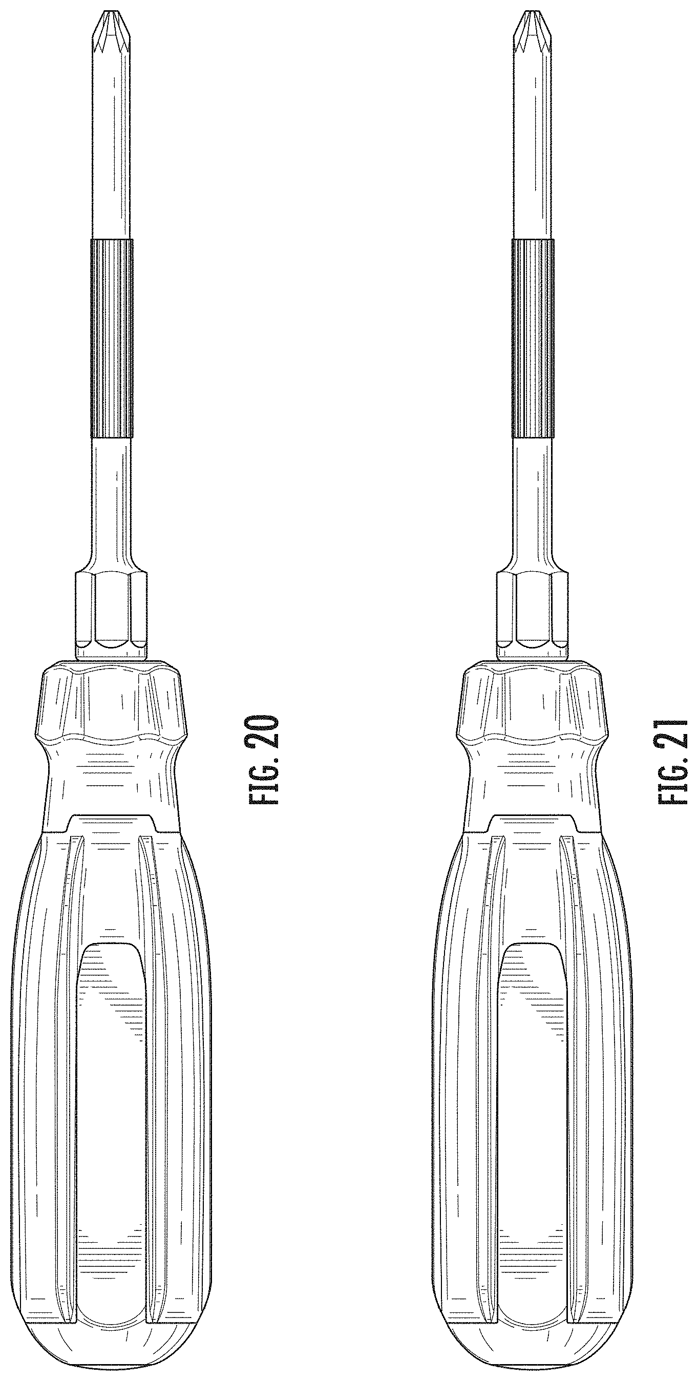
FIG. 20 is a third side view of the screwdriver of FIG. 15.
FIG. 21 is a fourth side view of the screwdriver of FIG. 15.
FIG. 22 is another perspective view of the first embodiment of the screwdriver, wherein the screwdriver is illustrated using wireframe drawing technique.
FIG. 23 is a first side view of the screwdriver of FIG. 22.
FIG. 24 is a second side view of the screwdriver of FIG. 22.
FIG. 25 is a front side view of the screwdriver of FIG. 22.
FIG. 26 is a back side view of the screwdriver of FIG. 22.
FIG. 27 is a third side view of the screwdriver of FIG. 22.
FIG. 28 is a fourth side view of the screwdriver of FIG. 22.
FIG. 29 is another perspective view of the second embodiment of the screwdriver wherein the screwdriver is illustrated using wireframe drawing technique.
FIG. 30 is a first side view of the screwdriver of FIG. 29.
FIG. 31 is a second side view of the screwdriver of FIG. 29.
FIG. 32 is a front side view of the screwdriver of FIG. 29.
FIG. 33 is a back side view of the screwdriver of FIG. 29.
FIG. 34 is a third side view of the screwdriver of FIG. 29.
FIG. 35 is a fourth side view of the screwdriver of FIG. 29.
FIG. 36 is another perspective view of the third embodiment of the screwdriver wherein the screwdriver is illustrated using wireframe drawing technique.
FIG. 37 is a first side view of the screwdriver of FIG. 36.
FIG. 38 is a second side view of the screwdriver of FIG. 36.
FIG. 39 is a front side view of the screwdriver of FIG. 36.
FIG. 40 is a back side view of the screwdriver of FIG. 36.
FIG. 41 is a third side view of the screwdriver of FIG. 36; and,
FIG. 42 is a fourth side view of the screwdriver of FIG. 36.
* * * * *
D00000
D00001
D00002
D00003
D00004
D00005
D00006
D00007
D00008
D00009
D00010
D00011
D00012
D00013

D00014

D00015

D00016

D00017

D00018

D00019

D00020

D00021

D00022

D00023

D00024

XML
uspto.report is an independent third-party trademark research tool that is not affiliated, endorsed, or sponsored by the United States Patent and Trademark Office (USPTO) or any other governmental organization. The information provided by uspto.report is based on publicly available data at the time of writing and is intended for informational purposes only.
While we strive to provide accurate and up-to-date information, we do not guarantee the accuracy, completeness, reliability, or suitability of the information displayed on this site. The use of this site is at your own risk. Any reliance you place on such information is therefore strictly at your own risk.
All official trademark data, including owner information, should be verified by visiting the official USPTO website at www.uspto.gov. This site is not intended to replace professional legal advice and should not be used as a substitute for consulting with a legal professional who is knowledgeable about trademark law.