Adaptor for supporting an electronic device
Stener February 9, 2
U.S. patent number D909,854 [Application Number D/740,038] was granted by the patent office on 2021-02-09 for adaptor for supporting an electronic device. This patent grant is currently assigned to Wild West Investments, LLC. The grantee listed for this patent is Wild West Investments, LLC. Invention is credited to Gavin Stener.


| United States Patent | D909,854 |
| Stener | February 9, 2021 |
Adaptor for supporting an electronic device
Claims
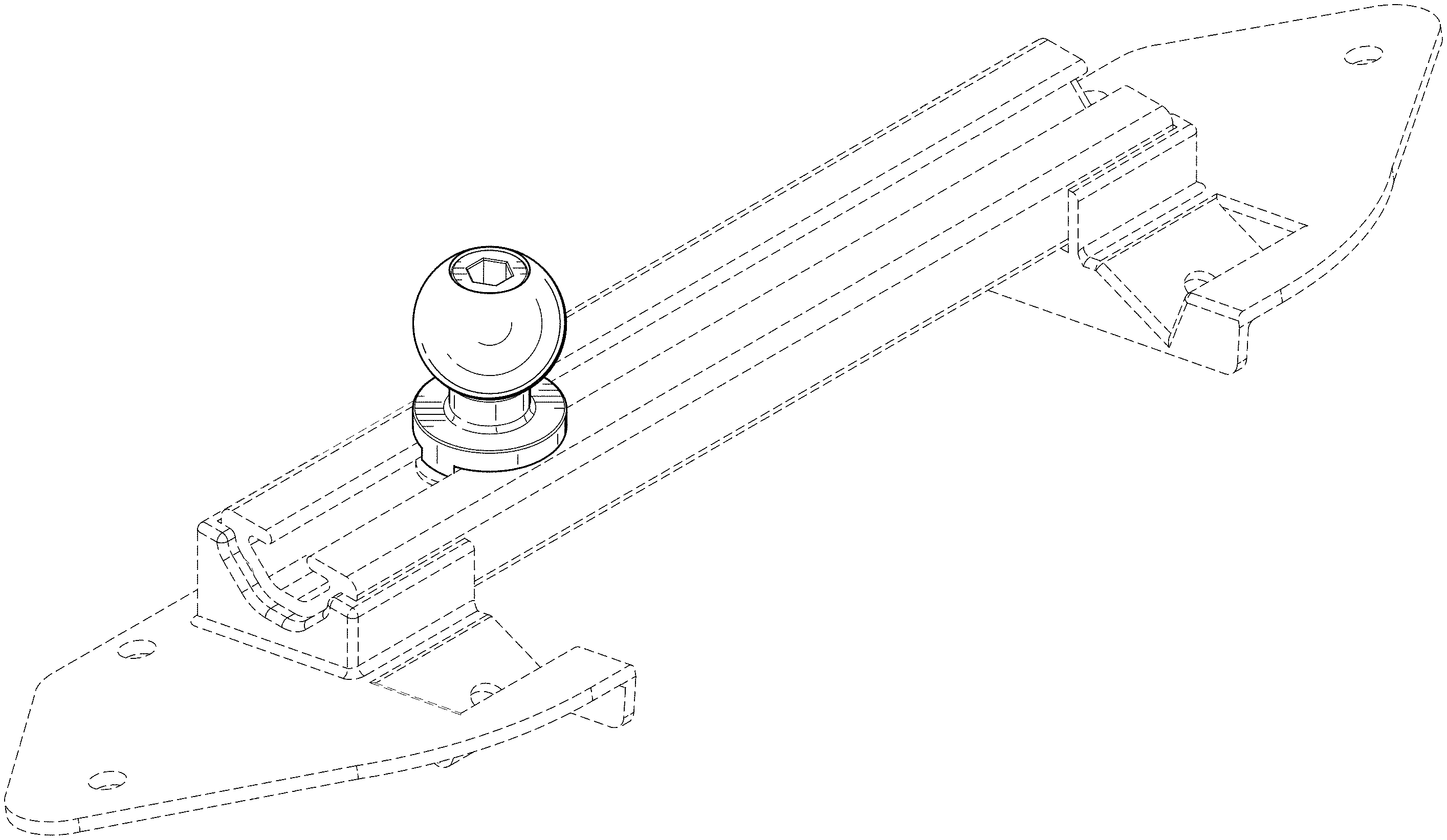
CLAIM An ornamental design for an adaptor for supporting an electronic device, as shown and described.
| Inventors: | Stener; Gavin (Dallas, TX) | ||||||||||
|---|---|---|---|---|---|---|---|---|---|---|---|
| Applicant: |
|
||||||||||
| Assignee: | Wild West Investments, LLC
(Dallas, TX) |
||||||||||
| Appl. No.: | D/740,038 | ||||||||||
| Filed: | June 30, 2020 |
Related U.S. Patent Documents
| Application Number | Filing Date | Patent Number | Issue Date | ||
|---|---|---|---|---|---|
| 29703584 | Aug 28, 2019 | ||||
| 29686974 | Apr 9, 2019 | D862213 | |||
| 29663162 | Sep 12, 2018 | D845111 | |||
| 29654050 | Jun 20, 2018 | D838579 | |||
| Current U.S. Class: | D8/380 |
| Current International Class: | 0805 |
| Field of Search: | ;D14/371-382,125-129,336,337,447-452,492,335,376-382,239,457,439-441,432,251-253 ;D8/349,354,363,373,376,380 ;D21/333 ;D12/162,415 ;D3/10,218 ;348/180,184,325,739,825 ;248/323,278.1,286.1 ;280/507,511 |
References Cited [Referenced By]
U.S. Patent Documents
| 4596406 | June 1986 | Van Vleet |
| 5395131 | March 1995 | Herrick |
| D375065 | October 1996 | Duvernay |
| D376780 | December 1996 | McCoy |
| 5839744 | November 1998 | Marks |
| 5890726 | April 1999 | McCoy |
| D526939 | August 2006 | Profit |
| D607381 | January 2010 | Lekkas |
| D879671 | March 2020 | Siegel |
| 2001/0045725 | November 2001 | McCoy |
| 2005/0104327 | May 2005 | Irgens |
| 2008/0272574 | November 2008 | Stuart |
| 2009/0026730 | January 2009 | Frantz |
Attorney, Agent or Firm: Foley & Lardner LLP
Description
This is a Divisional Application of U.S. Design Application having Ser. No. 29/708,370 filed on Oct. 4, 2019 (now U.S. Pat. No. D888,543).
FIG. 1 is an illustration of a front perspective view of an adaptor for supporting an electronic device;
FIG. 2 is a front elevational view thereof;
FIG. 3 is a rear elevational view thereof;
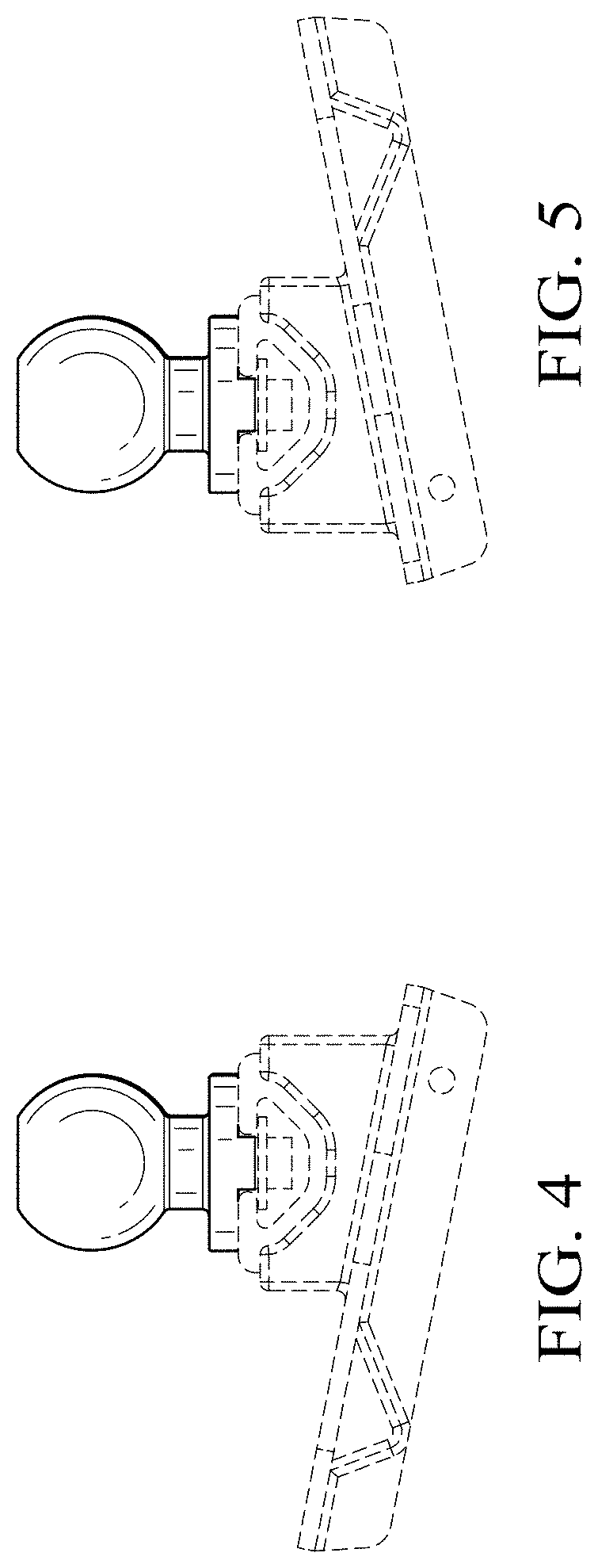
FIG. 4 is a right-side elevational view thereof;
FIG. 5 is a left-side elevational view thereof;
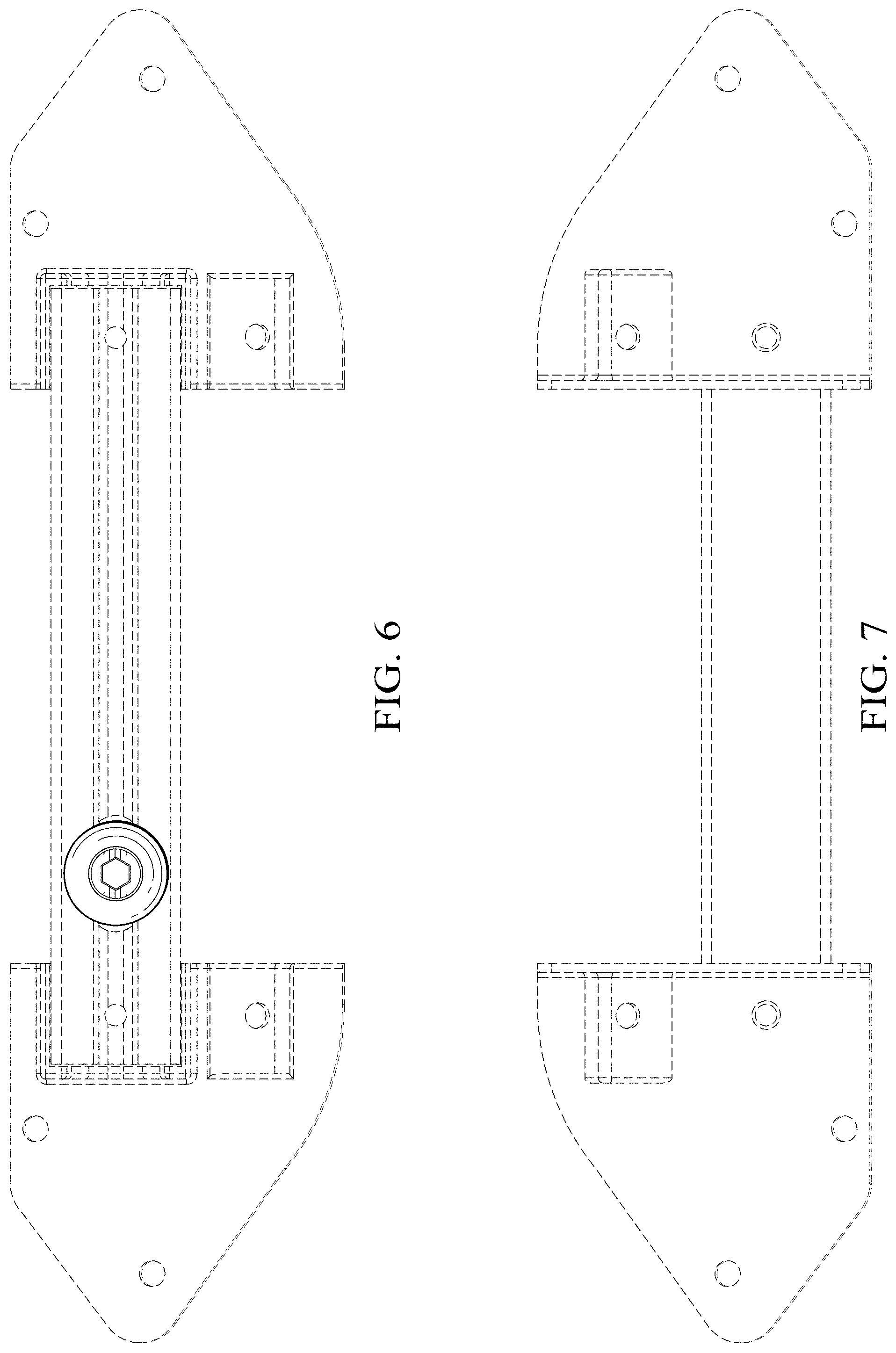
FIG. 6 is a top view thereof; and,
FIG. 7 is a bottom view thereof.
The broken lines shown as dashed lines are for the purpose of illustrating unclaimed structure, and form no part of the claimed design.
* * * * *
D00000
D00001
D00002
D00003
D00004
XML
uspto.report is an independent third-party trademark research tool that is not affiliated, endorsed, or sponsored by the United States Patent and Trademark Office (USPTO) or any other governmental organization. The information provided by uspto.report is based on publicly available data at the time of writing and is intended for informational purposes only.
While we strive to provide accurate and up-to-date information, we do not guarantee the accuracy, completeness, reliability, or suitability of the information displayed on this site. The use of this site is at your own risk. Any reliance you place on such information is therefore strictly at your own risk.
All official trademark data, including owner information, should be verified by visiting the official USPTO website at www.uspto.gov. This site is not intended to replace professional legal advice and should not be used as a substitute for consulting with a legal professional who is knowledgeable about trademark law.