Camera system
Voron , et al. February 2, 2
U.S. patent number D909,445 [Application Number D/639,633] was granted by the patent office on 2021-02-02 for camera system. This patent grant is currently assigned to Dolby Laboratories Licensing Corporation. The grantee listed for this patent is Dolby Laboratories Licensing Corporation. Invention is credited to Samuel James Fleming Carr, Christine Anna Livaudais, Peter Michaelian, Vincent Voron, Drew Alexander Walcott.


| United States Patent | D909,445 |
| Voron , et al. | February 2, 2021 |
Camera system
Claims
CLAIM The ornamental design for a camera system, as shown and described.
| Inventors: | Voron; Vincent (Menlo Park, CA), Michaelian; Peter (Tappan, NY), Livaudais; Christine Anna (San Francisco, CA), Walcott; Drew Alexander (San Francisco, CA), Carr; Samuel James Fleming (San Francisco, CA) | ||||||||||
|---|---|---|---|---|---|---|---|---|---|---|---|
| Applicant: |
|
||||||||||
| Assignee: | Dolby Laboratories Licensing
Corporation (San Francisco, CA) |
||||||||||
| Appl. No.: | D/639,633 | ||||||||||
| Filed: | March 7, 2018 |
| Current U.S. Class: | D16/202 |
| Current International Class: | 1601 |
| Field of Search: | ;D10/61,63,65,70,71,104.1,106.7 ;D16/200,202-203,207,208,218,219 ;D14/203.1,204,209.1,496,497 ;348/14.01-14.6,373-376 ;396/427,535,539-541 |
References Cited [Referenced By]
U.S. Patent Documents
| 6738094 | May 2004 | Minami et al. |
| D497925 | November 2004 | Zhang et al. |
| 6845954 | January 2005 | Moayer et al. |
| 7572073 | August 2009 | Kenoyer et al. |
| D627813 | November 2010 | Chen et al. |
| D631497 | January 2011 | Han |
| D641388 | July 2011 | Shih |
| D643456 | August 2011 | Won et al. |
| D665439 | August 2012 | Khamsepoor |
| D669108 | October 2012 | Maeyama |
| D680144 | April 2013 | Tsai |
| D680569 | April 2013 | Lee |
| D682332 | May 2013 | Wang |
| D685015 | June 2013 | Wang |
| 8593567 | November 2013 | Xiao |
| D709117 | July 2014 | Gan |
| D712946 | September 2014 | Hong |
| D745586 | December 2015 | Chou et al. |
| D800201 | October 2017 | Song |
| D849086 | May 2019 | Russo |
| D872792 | January 2020 | Fletcher |
| 2005/0231587 | October 2005 | Root et al. |
Other References
|
Avaya, Scopia.RTM. XT Executive 240 (55411-00001), <https://support.avaya.com/products/P1455/scopia-xt-executive-240>. cited by applicant. |
Primary Examiner: Almatrahi; Ramzi S
Attorney, Agent or Firm: Saidman DesignLaw Group, LLC
Description
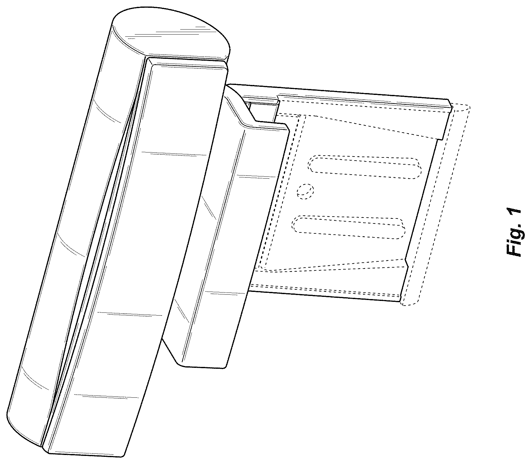
FIG. 1 is a perspective view of a camera system showing our new design;
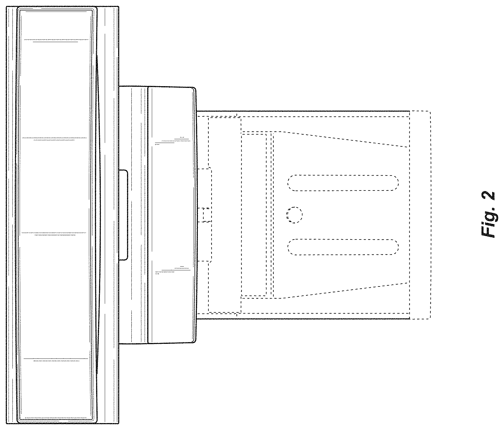
FIG. 2 is a front view thereof;
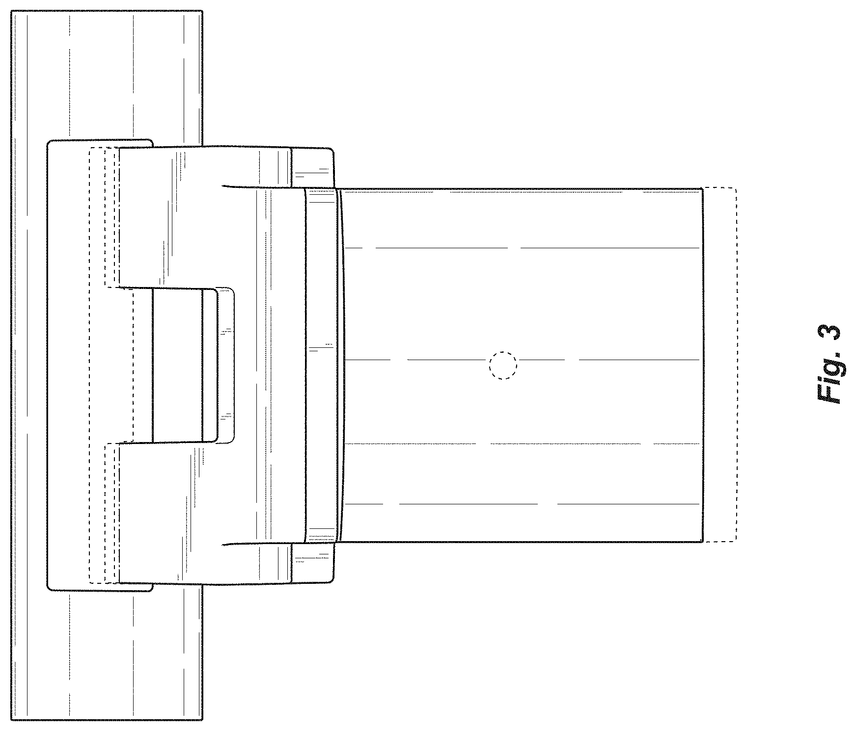
FIG. 3 is a rear view thereof;
FIG. 4 is a left side view thereof;
FIG. 5 is a right side view thereof;
FIG. 6 is a top view thereof; and,
FIG. 7 is a bottom view thereof.
The broken lines illustrate portions of the camera system which form no part of the claimed design. Additionally, the dash-dot lines denote the boundary of the claim and form no part of the claimed design.
The drawings include surface shading which illustrates contour and not surface ornamentation.
* * * * *
References
D00000
D00001
D00002
D00003
D00004
D00005
D00006
XML
uspto.report is an independent third-party trademark research tool that is not affiliated, endorsed, or sponsored by the United States Patent and Trademark Office (USPTO) or any other governmental organization. The information provided by uspto.report is based on publicly available data at the time of writing and is intended for informational purposes only.
While we strive to provide accurate and up-to-date information, we do not guarantee the accuracy, completeness, reliability, or suitability of the information displayed on this site. The use of this site is at your own risk. Any reliance you place on such information is therefore strictly at your own risk.
All official trademark data, including owner information, should be verified by visiting the official USPTO website at www.uspto.gov. This site is not intended to replace professional legal advice and should not be used as a substitute for consulting with a legal professional who is knowledgeable about trademark law.