Maxillary frenum clamping tool
Alsarhan January 26, 2
U.S. patent number D908,877 [Application Number D/703,488] was granted by the patent office on 2021-01-26 for maxillary frenum clamping tool. This patent grant is currently assigned to KING SAUD UNIVERSITY. The grantee listed for this patent is KING SAUD UNIVERSITY. Invention is credited to Mohammed Abdullah Alsarhan.


| United States Patent | D908,877 |
| Alsarhan | January 26, 2021 |
Maxillary frenum clamping tool
Claims
CLAIM The ornamental design for a maxillary frenum clamping tool, as shown and described.
| Inventors: | Alsarhan; Mohammed Abdullah (Riyadh, SA) | ||||||||||
|---|---|---|---|---|---|---|---|---|---|---|---|
| Applicant: |
|
||||||||||
| Assignee: | KING SAUD UNIVERSITY (Riyadh,
SA) |
||||||||||
| Appl. No.: | D/703,488 | ||||||||||
| Filed: | August 27, 2019 |
| Current U.S. Class: | D24/143; D24/152 |
| Current International Class: | 2402 |
| Field of Search: | ;D24/143,146-148,133,152 ;D8/52-54,57 |
References Cited [Referenced By]
U.S. Patent Documents
| 3364933 | January 1968 | Leopold |
| 3823719 | July 1974 | Cummings |
| 4655223 | April 1987 | Kim |
| 5059214 | October 1991 | Akopov et al. |
| 5133737 | July 1992 | Grismer |
| 5251642 | October 1993 | Handlos |
| D581053 | November 2008 | Gesler, III |
| 9237899 | January 2016 | Ray |
| D802133 | November 2017 | Thrasher, III |
| 10646243 | May 2020 | Alsarhan |
| 2007/0299470 | December 2007 | Vanden Hoek |
| 2008/0172085 | July 2008 | Chiu |
| 2008/0300622 | December 2008 | Xu |
| 2014/0046363 | February 2014 | Frimand Ronnow |
| 424807 | Feb 1926 | DE | |||
Attorney, Agent or Firm: Nath, Goldberg & Meyer Litman; Richard C.
Description
FIG. 1 is a perspective view of a maxillary frenum clamping tool showing my new design;
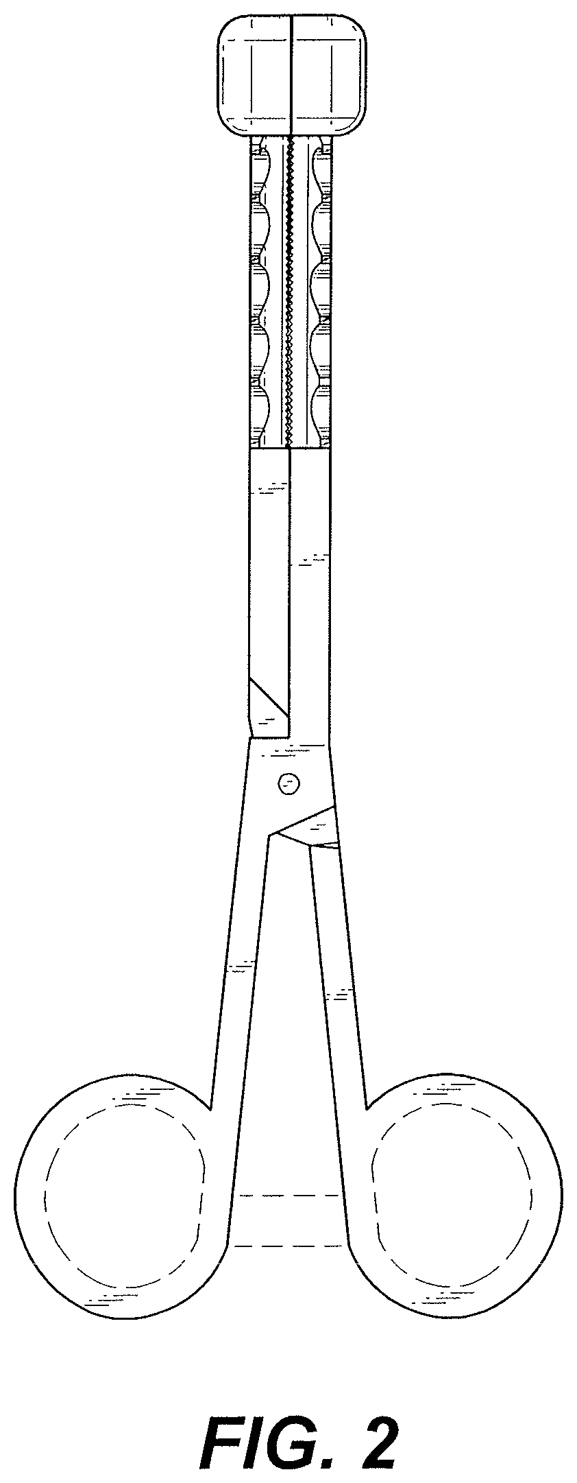
FIG. 2 is a front elevational view thereof;
FIG. 3 is a rear elevational view thereof;
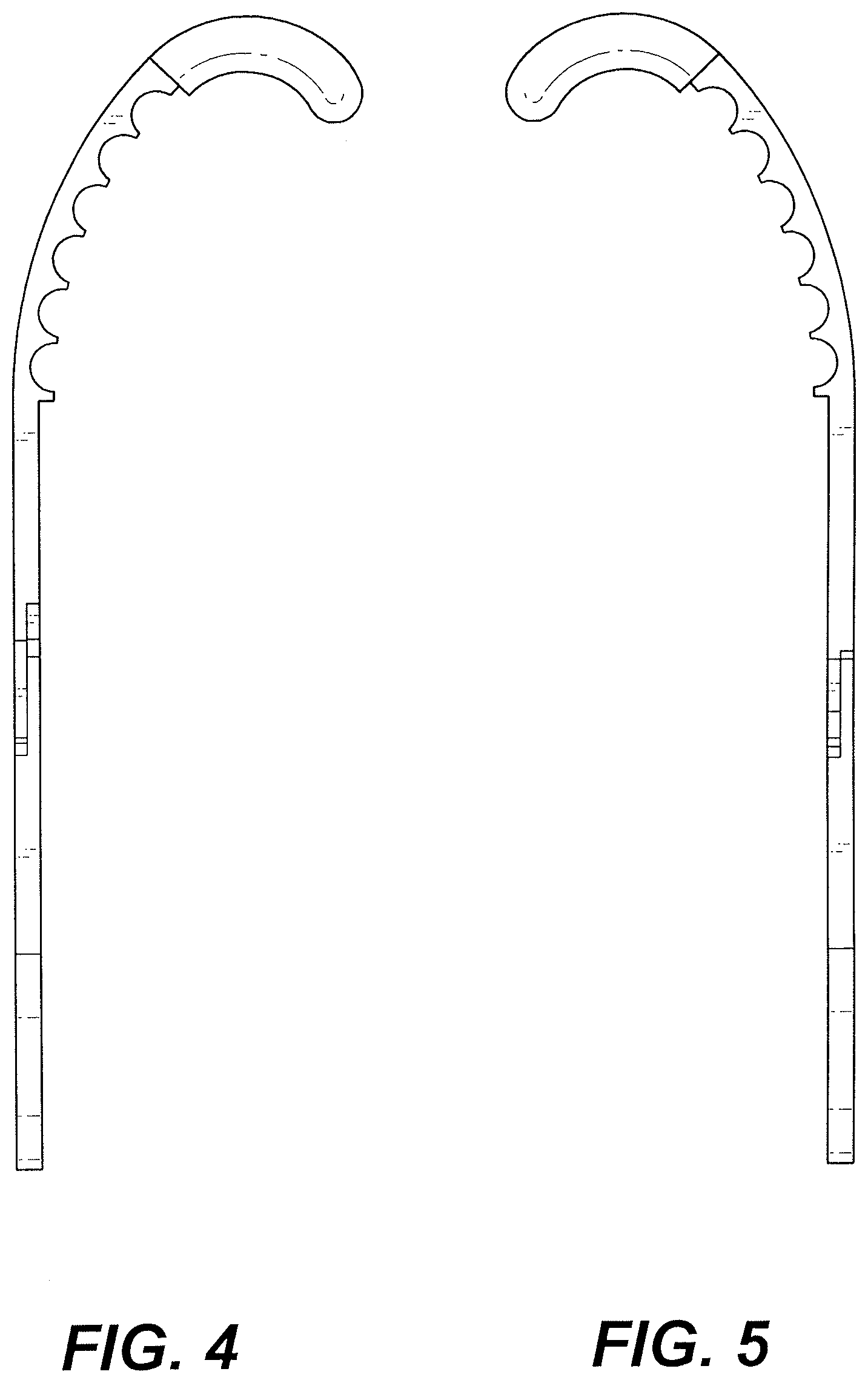
FIG. 4 is a right side elevational view;
FIG. 5 is a left side elevational view;
FIG. 6 is a top view thereof;
FIG. 7 is a bottom view thereof; and,
FIG. 8 is a perspective view shown with the clamping tool pivoted to an open position.
The broken lines in FIGS. 1 and 8 are for illustrative purposes only; the broken lines representing the holes in the finger loops are shown as being circular, but may be oval or D- shaped, the shape of the holes in the finger loops form no part of the claimed design. Similarly, the broken lines show the clamp locking mechanism as linear, but it may be arcuate or arched. The shape of the clamp locking mechanism forms no part of the claimed design
* * * * *
D00000
D00001
D00002
D00003
D00004
D00005
D00006
XML
uspto.report is an independent third-party trademark research tool that is not affiliated, endorsed, or sponsored by the United States Patent and Trademark Office (USPTO) or any other governmental organization. The information provided by uspto.report is based on publicly available data at the time of writing and is intended for informational purposes only.
While we strive to provide accurate and up-to-date information, we do not guarantee the accuracy, completeness, reliability, or suitability of the information displayed on this site. The use of this site is at your own risk. Any reliance you place on such information is therefore strictly at your own risk.
All official trademark data, including owner information, should be verified by visiting the official USPTO website at www.uspto.gov. This site is not intended to replace professional legal advice and should not be used as a substitute for consulting with a legal professional who is knowledgeable about trademark law.