Receptacle holder
Buse January 19, 2
U.S. patent number D908,240 [Application Number D/735,363] was granted by the patent office on 2021-01-19 for receptacle holder. This patent grant is currently assigned to GEN-PROBE INCORPORATED. The grantee listed for this patent is GEN-PROBE INCORPORATED. Invention is credited to David A. Buse.


| United States Patent | D908,240 |
| Buse | January 19, 2021 |
Receptacle holder
Claims
CLAIM The ornamental design for a receptacle holder, as shown and described.
| Inventors: | Buse; David A. (San Diego, CA) | ||||||||||
|---|---|---|---|---|---|---|---|---|---|---|---|
| Applicant: |
|
||||||||||
| Assignee: | GEN-PROBE INCORPORATED (San
Diego, CA) |
||||||||||
| Appl. No.: | D/735,363 | ||||||||||
| Filed: | May 20, 2020 |
Related U.S. Patent Documents
| Application Number | Filing Date | Patent Number | Issue Date | ||
|---|---|---|---|---|---|
| 29698619 | Jul 18, 2019 | D888279 | |||
| 29610161 | Aug 6, 2019 | D855826 | |||
| Current U.S. Class: | D24/227 |
| Current International Class: | 2402 |
| Field of Search: | ;D24/107,108,121,224-227,230,231,232 |
References Cited [Referenced By]
U.S. Patent Documents
| 3469709 | September 1969 | Wood |
| 3994594 | November 1976 | Sandrock et al. |
| 5437841 | August 1995 | Balmer |
| D411308 | June 1999 | Pandey et al. |
| D438632 | March 2001 | Miller |
| D446311 | August 2001 | Wescott, III |
| D476088 | June 2003 | Wescott, III |
| D478193 | August 2003 | Routh |
| D674112 | January 2013 | Demas et al. |
| D685493 | July 2013 | Sato et al. |
| D735881 | August 2015 | Thomas |
| D808540 | January 2018 | Johns et al. |
| D810959 | February 2018 | Langhoff et al. |
| D849266 | May 2019 | Higgins |
| D852977 | July 2019 | Suchocki et al. |
| D853816 | July 2019 | Schaz et al. |
| D855826 | August 2019 | Buse |
| D877360 | March 2020 | Erb |
| D888279 | June 2020 | Buse |
| 10668472 | June 2020 | Knight |
| 2002/0030044 | March 2002 | Brown |
Assistant Examiner: Agilee; Omeed
Attorney, Agent or Firm: Sterne, Kessler, Goldstein & Fox P.L.L.C. Cappellari; Charles B.
Description
FIG. 1 is a top front perspective view of a receptacle holder showing the claimed design;
FIG. 2 is a bottom rear perspective view thereof;
FIG. 3 is a front view thereof;
FIG. 4 is a rear view thereof;
FIG. 5 is a left side view thereof;
FIG. 6 is a right side view thereof;
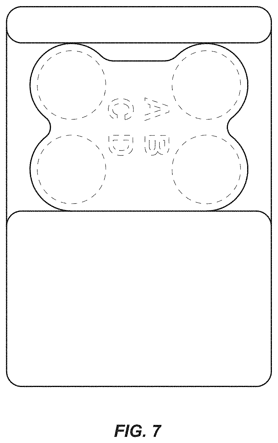
FIG. 7 is a top view thereof; and,
FIG. 8 is a bottom view thereof.
The broken lines in the figures show portions of the receptacle holder that form no part of the claimed design.
* * * * *
D00000
D00001
D00002
D00003
D00004
D00005
D00006
D00007
D00008
XML
uspto.report is an independent third-party trademark research tool that is not affiliated, endorsed, or sponsored by the United States Patent and Trademark Office (USPTO) or any other governmental organization. The information provided by uspto.report is based on publicly available data at the time of writing and is intended for informational purposes only.
While we strive to provide accurate and up-to-date information, we do not guarantee the accuracy, completeness, reliability, or suitability of the information displayed on this site. The use of this site is at your own risk. Any reliance you place on such information is therefore strictly at your own risk.
All official trademark data, including owner information, should be verified by visiting the official USPTO website at www.uspto.gov. This site is not intended to replace professional legal advice and should not be used as a substitute for consulting with a legal professional who is knowledgeable about trademark law.