Transcutaneous neuromodulation device
Chu , et al. January 19, 2
U.S. patent number D908,230 [Application Number D/675,968] was granted by the patent office on 2021-01-19 for transcutaneous neuromodulation device. This patent grant is currently assigned to Apex Neuro Holdings, Inc.. The grantee listed for this patent is Apex Neuro Inc.. Invention is credited to Geoff Baldwin, Zen Chu, Sean Hagberg, Thomas Kershaw, Francois Kress, Jainam Shah, Priyanka Venkatesh, Christopher Wright.


View All Diagrams
| United States Patent | D908,230 |
| Chu , et al. | January 19, 2021 |
Transcutaneous neuromodulation device
Claims
CLAIM The ornamental design for a transcutaneous neuromodulation device, substantially as shown and described.
| Inventors: | Chu; Zen (Brookline, MA), Hagberg; Sean (Cranston, RI), Kress; Francois (New York, NY), Shah; Jainam (Cambridge, MA), Baldwin; Geoff (Cambridge, MA), Venkatesh; Priyanka (New York, NY), Wright; Christopher (Somerville, MA), Kershaw; Thomas (Swampscott, MA) | ||||||||||
|---|---|---|---|---|---|---|---|---|---|---|---|
| Applicant: |
|
||||||||||
| Assignee: | Apex Neuro Holdings, Inc.
(Brooklyn, NY) |
||||||||||
| Appl. No.: | D/675,968 | ||||||||||
| Filed: | January 7, 2019 |
| Current U.S. Class: | D24/200 |
| Current International Class: | 2803 |
| Field of Search: | ;D24/200,185-187,214,107 |
References Cited [Referenced By]
U.S. Patent Documents
| 6077237 | June 2000 | Campbell |
| D615209 | May 2010 | Minogue |
| 8682452 | March 2014 | Minogue |
| 8914123 | December 2014 | Rigaux |
| D752766 | March 2016 | Guarraia |
| D816227 | April 2018 | Geissen |
| 10695568 | June 2020 | Covalin |
| 2008/0097549 | April 2008 | Colbaugh |
| 2019/0232046 | August 2019 | Chu |
| 2019/0232047 | August 2019 | Chu |
Attorney, Agent or Firm: Hassid; Steve Partners Law Group, Inc.
Description
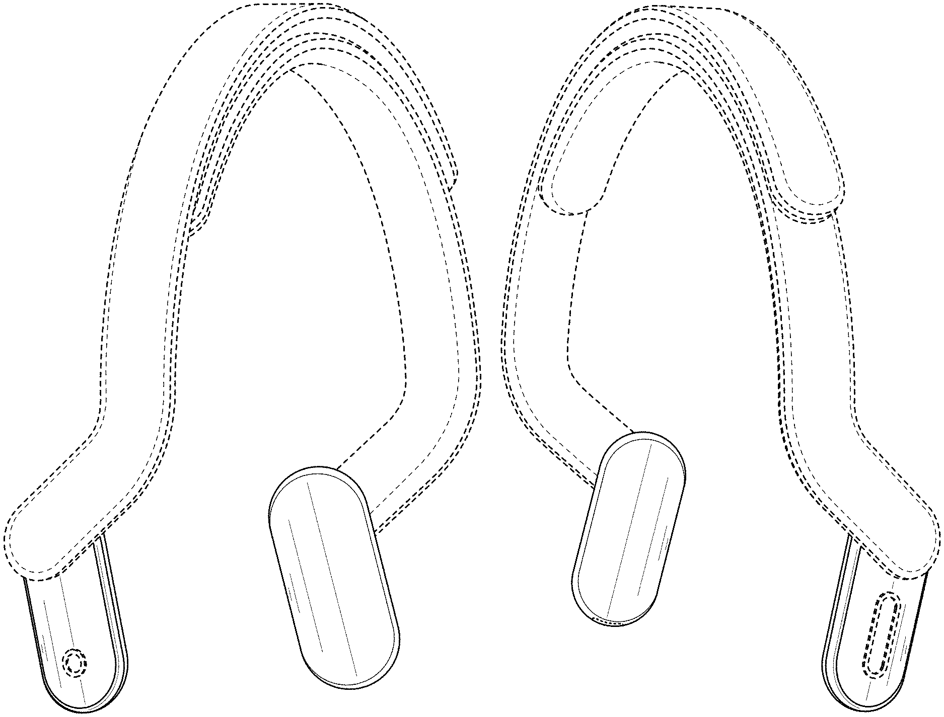
FIG. 1 is a perspective view of a transcutaneous neuromodulation device in accordance with our new design, where the device generally a headband component for engaging a wearer's head and connecting to two user interface components generally aligned with the wearer's mastoid region;
FIG. 2 is a perspective view of the transcutaneous neuromodulation device of FIG. 1, rotated 180 degrees;
FIG. 3 is a perspective view of the transcutaneous neuromodulation device of FIG. 1, rotated to show an underside of the device.
FIG. 4 is a is a front view of the transcutaneous neuromodulation device of FIG. 1
FIG. 5 is a is a rear view of the transcutaneous neuromodulation device of FIG. 1;
FIG. 6 is a right side view of the transcutaneous neuromodulation device of FIG. 1;
FIG. 7 is a left side view of the transcutaneous neuromodulation device of FIG. 1;
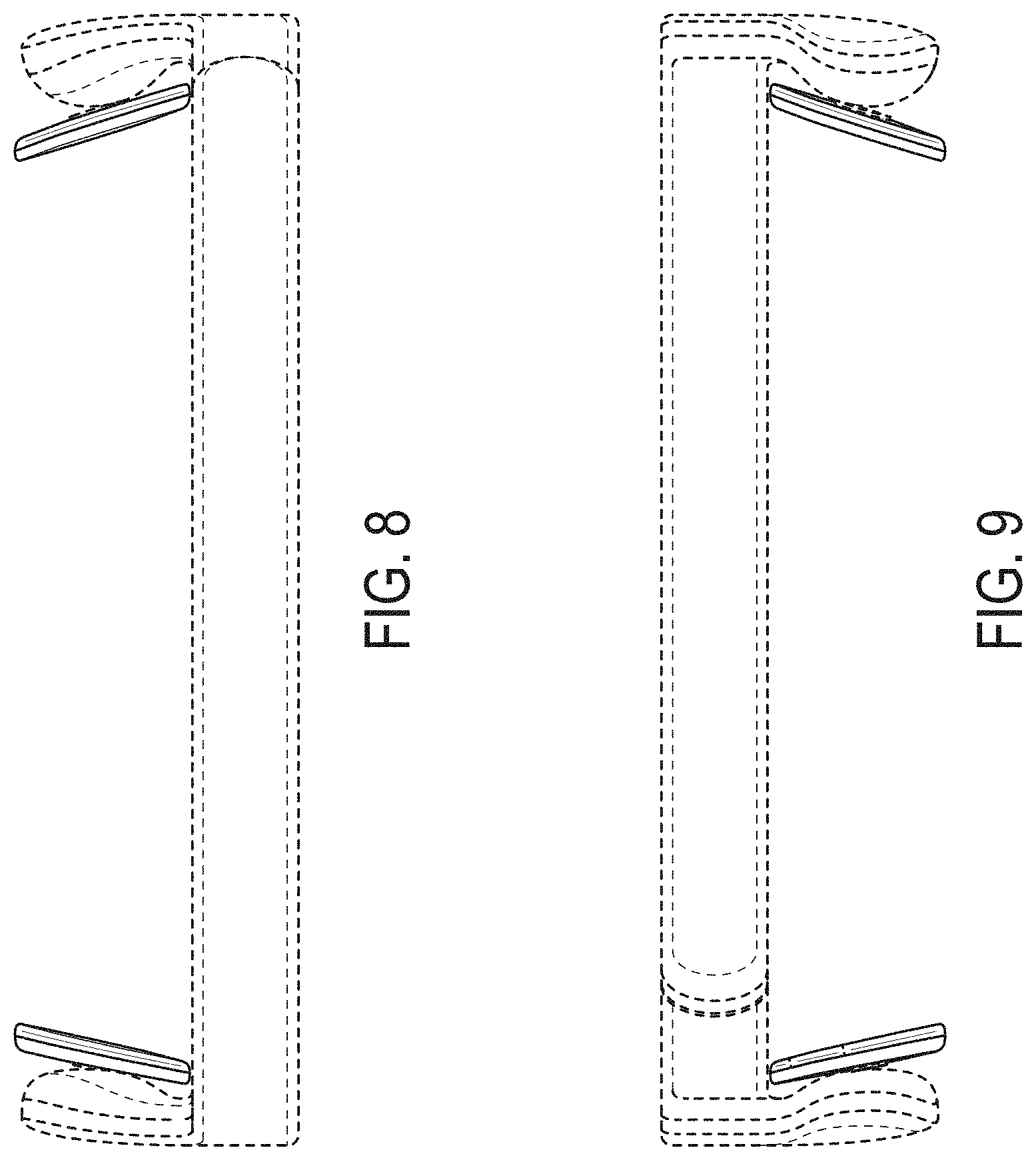
FIG. 8 is a top view of the transcutaneous neuromodulation device of FIG. 1;
FIG. 9 is a bottom view of the transcutaneous neuromodulation device of FIG. 1;
FIG. 10 is an enlarged right side view of the distal ends of the transcutaneous neuromodulation device of FIG. 1 depicting an inner surface of a left interface component that engages with the wearer's mastoid region (far view) and an outer surface of a right interface component (near view) where any controls, indicators, sensors, or other interactive components may be located;
FIG. 11 is an enlarged left side view of a distal end of the transcutaneous neuromodulation device of FIG. 1 depicting the outer surface of the left interface component where any controls, indicators, sensors, or other interactive devices may be located;
FIG. 12 is a right side view of the distal end of the transcutaneous neuromodulation device of FIG. 3, rotated 90 degrees to depict the right interface component coupled to the headband component and to further depict any interactive devices may be located on the interface component;
FIG. 13 is a rear perspective view of the transcutaneous neuromodulation device of FIG. 1 disposed on a wearer's head; and,
FIG. 14 is a left side view of the transcutaneous neuromodulation device of FIG. 1 disposed on the wearer's head.
The features shown in broken lines in various figures are for illustrating environmental structure and form no part of the claimed design.
The device or any portion thereof is not limited to the scale shown herein.
The invention can be any part, portion, element, or combination of elements of the depicted design.
Omitted views of the device of our new design are clearly understood and fully disclosed in the perspective views shown in the figures.
* * * * *
D00000
D00001
D00002
D00003
D00004
D00005
D00006
D00007
D00008
D00009
D00010
D00011
XML
uspto.report is an independent third-party trademark research tool that is not affiliated, endorsed, or sponsored by the United States Patent and Trademark Office (USPTO) or any other governmental organization. The information provided by uspto.report is based on publicly available data at the time of writing and is intended for informational purposes only.
While we strive to provide accurate and up-to-date information, we do not guarantee the accuracy, completeness, reliability, or suitability of the information displayed on this site. The use of this site is at your own risk. Any reliance you place on such information is therefore strictly at your own risk.
All official trademark data, including owner information, should be verified by visiting the official USPTO website at www.uspto.gov. This site is not intended to replace professional legal advice and should not be used as a substitute for consulting with a legal professional who is knowledgeable about trademark law.