Optical fiber connector
Watanabe , et al. January 19, 2
U.S. patent number D908,088 [Application Number D/634,396] was granted by the patent office on 2021-01-19 for optical fiber connector. This patent grant is currently assigned to SUMITOMO ELECTRIC INDUSTRIES, LTD.. The grantee listed for this patent is SUMITOMO ELECTRIC INDUSTRIES, LTD.. Invention is credited to Takako Hosokawa, Dai Sasaki, Yoshikyo Tamekuni, Takuro Watanabe.


View All Diagrams
| United States Patent | D908,088 |
| Watanabe , et al. | January 19, 2021 |
Optical fiber connector
Claims
CLAIM The ornamental design for an optical fiber connector, as shown and described.
| Inventors: | Watanabe; Takuro (Osaka, JP), Sasaki; Dai (Osaka, JP), Tamekuni; Yoshikyo (Osaka, JP), Hosokawa; Takako (Osaka, JP) | ||||||||||
|---|---|---|---|---|---|---|---|---|---|---|---|
| Applicant: |
|
||||||||||
| Assignee: | SUMITOMO ELECTRIC INDUSTRIES,
LTD. (Osaka, JP) |
||||||||||
| Appl. No.: | D/634,396 | ||||||||||
| Filed: | January 22, 2018 |
Foreign Application Priority Data
| Aug 2, 2017 [JP] | 2017-016724 | |||
| Current U.S. Class: | D13/133; D13/147 |
| Current International Class: | 1303 |
| Field of Search: | ;D13/110,123,133,146,147,149,153,154,156,173,177,178,184,199 ;D14/480.1,480.5,480.6,480.7,484.1 |
References Cited [Referenced By]
U.S. Patent Documents
| 4397513 | August 1983 | Clark |
| D611418 | March 2010 | Kato |
| 9453963 | September 2016 | Sato |
| D881814 | April 2020 | Watanabe |
| 10666001 | May 2020 | Hou |
| 10705299 | July 2020 | Nakama |
| 10725247 | July 2020 | Takano |
| D892746 | August 2020 | Tsai |
| 10732366 | August 2020 | Turcotte |
| 2003/0169974 | September 2003 | Ngo |
| 2007/0217749 | September 2007 | Jong |
| 2011/0058774 | March 2011 | Gurreri |
| 2013/0108233 | May 2013 | Lin |
| 2013/0266268 | October 2013 | Li |
| 2015/0104135 | April 2015 | Bushnell |
| 2016/0259135 | September 2016 | Gniadek |
| 2016/0349459 | December 2016 | Collier |
| 2019/0187385 | June 2019 | Watanabe |
| 2019/0346630 | November 2019 | Yang |
| 2019/0353852 | November 2019 | Lee |
| 2020/0103604 | April 2020 | Bradley |
Other References
|
LC Fiber Optic Adapter With Shutter, dated Jul. 23, 2017, [online], [site visited Dec. 3, 2019]. Available from Internet, URL: http://www.springoptical.com/fiber-optic-adapters/lc-fiber-adapters/lc-fi- ber-optic-adapter-with-shutter.html (Year: 2017). cited by examiner . SC shutter patch cord, dated Aug. 29, 2018, [online], [site visited Dec. 3, 2019]. Available from Internet, URL: http://www.wirenet-tech.conn/index.php/products_v_20_178.html (Year: 2018). cited by examiner . Fiberwe SC adapter with shutter, dated Aug. 18, 2018, [online], [site visited Dec. 3, 2019]. Available from Internet, URL: http://fiberwe.com/products/fiber-optic-components/connectors-adapters/sc- -connector-adapter.htm (Year: 2018). cited by examiner. |
Primary Examiner: Lee; Angela J
Assistant Examiner: Gingrich; Shawn T
Attorney, Agent or Firm: Faegre Drinker Biddle & Reath LLP
Description
FIG. 1 is a front view of an optical fiber connector of the present invention;
FIG. 2 is a rear view thereof;
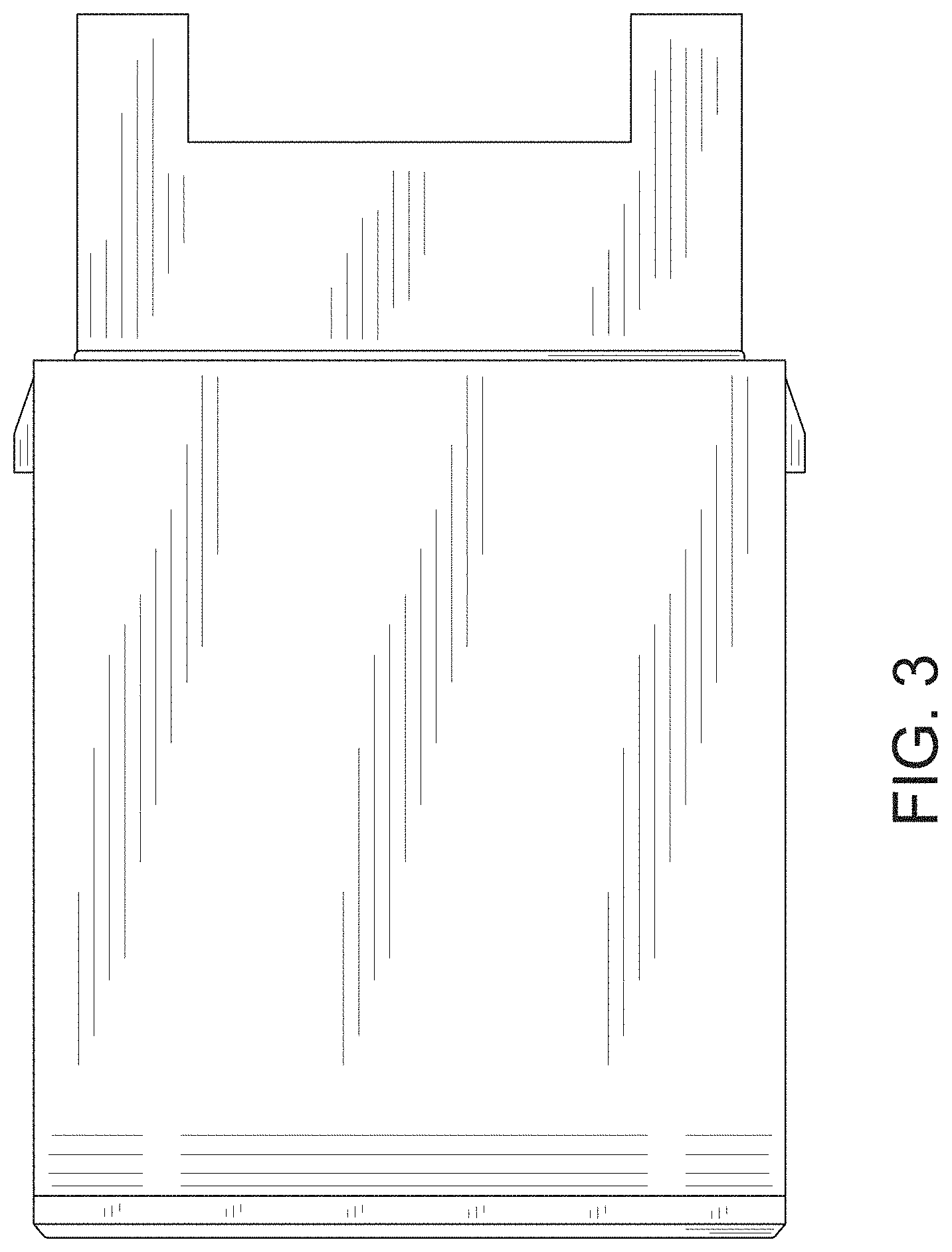
FIG. 3 is a top plan view thereof;
FIG. 4 is a bottom plan view thereof;
FIG. 5 is a right side view thereof;
FIG. 6 is a left side view thereof;
FIG. 7 is a front, top plan and left side perspective view thereof;
FIG. 8 is a rear, bottom plan and right side perspective view thereof;
FIG. 9 is a cross-sectional view along the line 9-9 in FIG. 1;
FIG. 10 is a cross-sectional view along the line 10-10 in FIG. 6;
FIG. 11 is a front view in the first alternate position thereof;
FIG. 12 is a left side view in the first alternate position thereof;
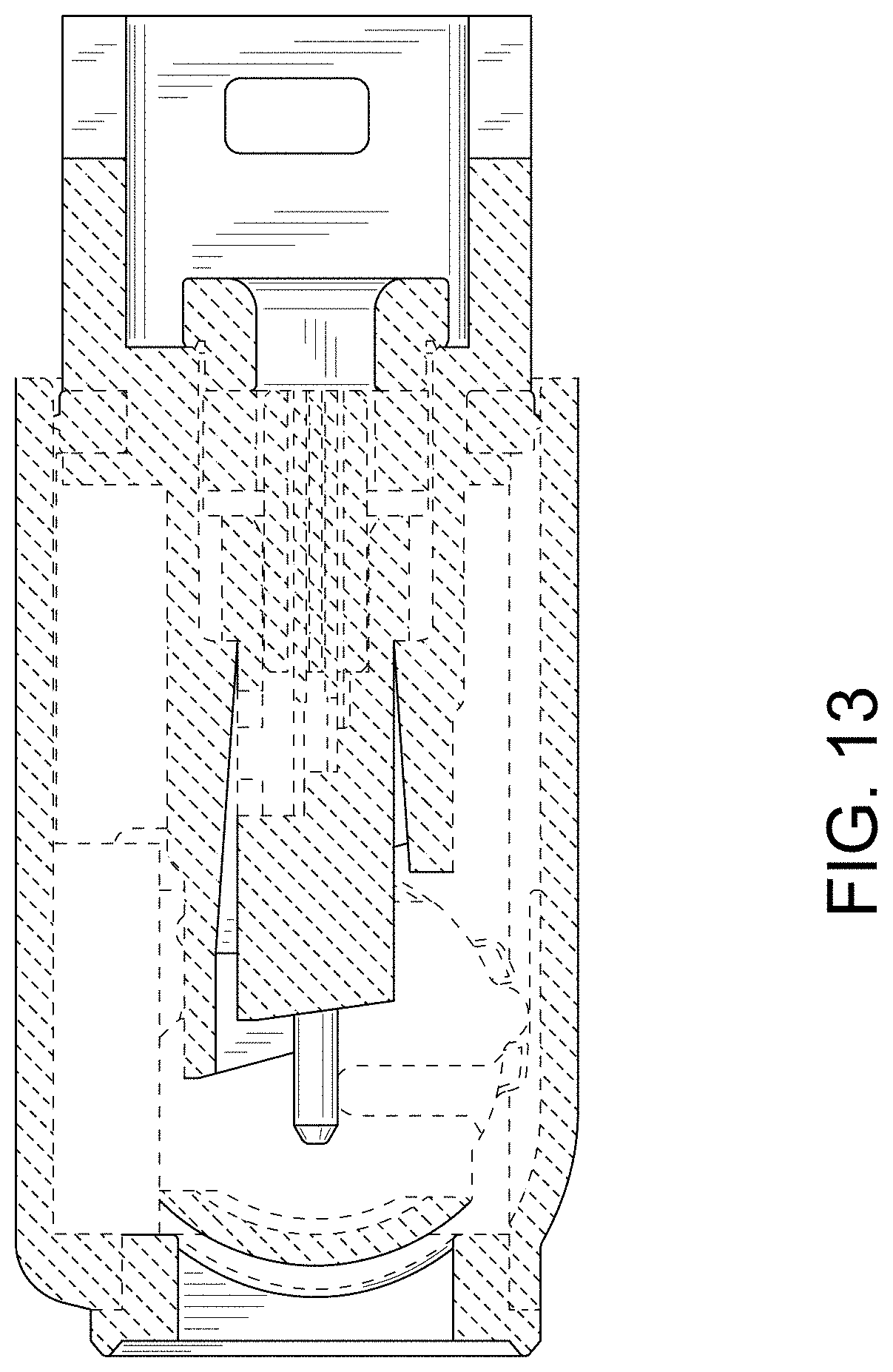
FIG. 13 is a cross-sectional view along the line 13-13 in FIG. 12;
FIG. 14 is a front view in the second alternate position thereof;
FIG. 15 is a left side view in the second alternate position thereof;
FIG. 16 is a cross-sectional view along the line 16-16 in FIG. 15;
FIG. 17 is a front view in the third alternate position thereof;
FIG. 18 is a rear view in the third alternate position thereof;
FIG. 19 is a top plan view in the third alternate position thereof;
FIG. 20 is a bottom plan view in the third alternate position thereof;
FIG. 21 is a right side view in the third alternate position thereof;
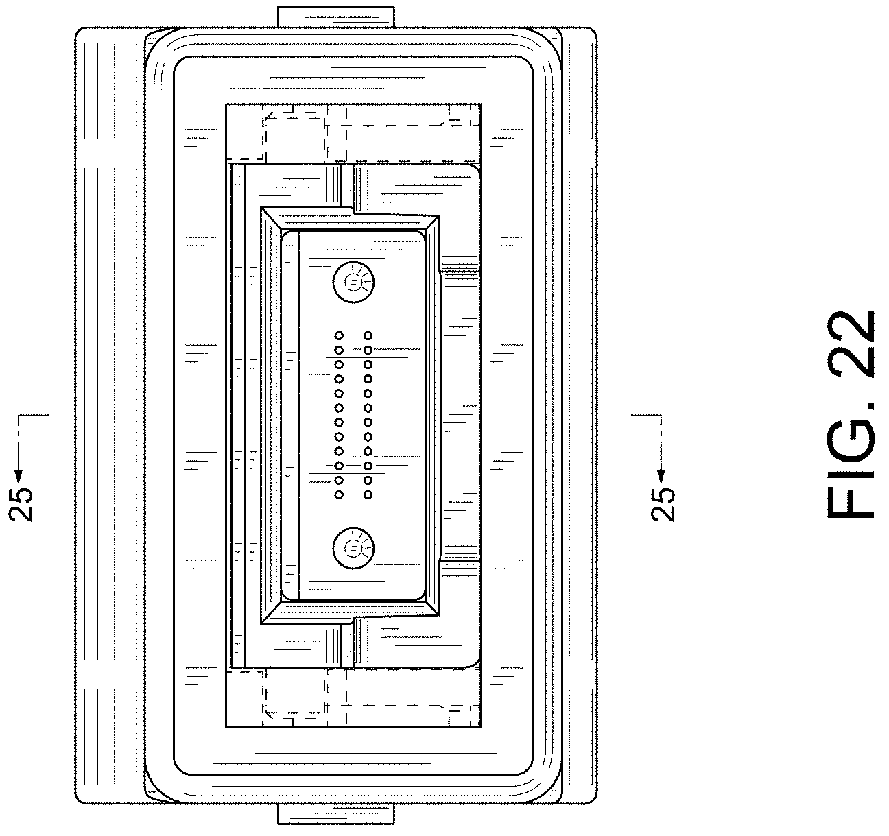
FIG. 22 is a left side view in the third alternate position thereof;
FIG. 23 is a front, top plan and left side perspective view in the third alternate position thereof;
FIG. 24 is a rear, bottom plan and right side perspective view in the third alternate position thereof; and,
FIG. 25 is a cross-sectional view along the line 25-25 in FIG. 22.
The features shown in broken lines depict environmental subject matter only and form no part of the claimed design. The unshaded surfaces form no part of the claimed design.
* * * * *
References
D00000
D00001
D00002
D00003
D00004
D00005
D00006
D00007
D00008
D00009
D00010
D00011
D00012

D00013
D00014

D00015

D00016

D00017

D00018

D00019

D00020

D00021

D00022
D00023

D00024

D00025

XML
uspto.report is an independent third-party trademark research tool that is not affiliated, endorsed, or sponsored by the United States Patent and Trademark Office (USPTO) or any other governmental organization. The information provided by uspto.report is based on publicly available data at the time of writing and is intended for informational purposes only.
While we strive to provide accurate and up-to-date information, we do not guarantee the accuracy, completeness, reliability, or suitability of the information displayed on this site. The use of this site is at your own risk. Any reliance you place on such information is therefore strictly at your own risk.
All official trademark data, including owner information, should be verified by visiting the official USPTO website at www.uspto.gov. This site is not intended to replace professional legal advice and should not be used as a substitute for consulting with a legal professional who is knowledgeable about trademark law.