Stand
Karlsson , et al. November 17, 2
U.S. patent number D902,208 [Application Number D/629,854] was granted by the patent office on 2020-11-17 for stand. This patent grant is currently assigned to PayPal, Inc.. The grantee listed for this patent is PAYPAL, INC.. Invention is credited to Nino Hoglund, Oscar Karlsson, Gustav Muller Nord.


| United States Patent | D902,208 |
| Karlsson , et al. | November 17, 2020 |
Stand
Claims
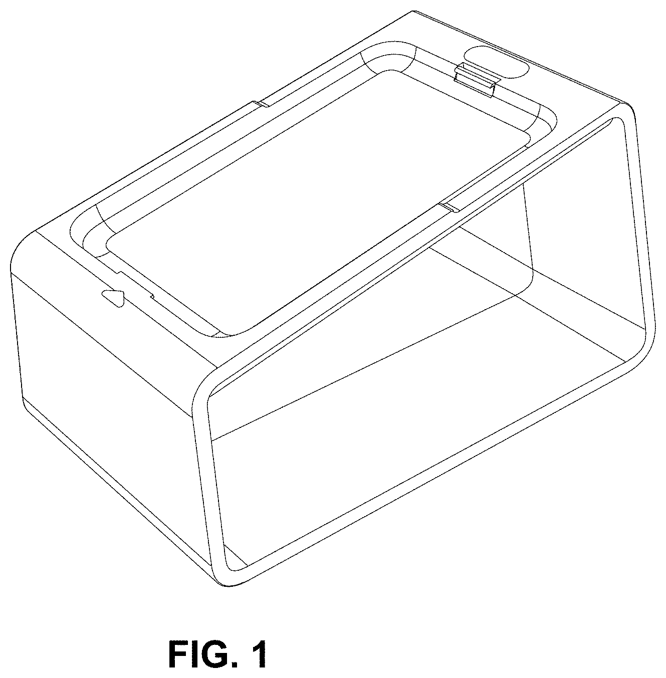
CLAIM The ornamental design for a stand, as shown and described.
| Inventors: | Karlsson; Oscar (Skarmpack, SE), Hoglund; Nino (Stockholm, SE), Nord; Gustav Muller (Nacka, SE) | ||||||||||
|---|---|---|---|---|---|---|---|---|---|---|---|
| Applicant: |
|
||||||||||
| Assignee: | PayPal, Inc. (San Jose,
CA) |
||||||||||
| Appl. No.: | D/629,854 | ||||||||||
| Filed: | December 15, 2017 |
Related U.S. Patent Documents
| Application Number | Filing Date | Patent Number | Issue Date | ||
|---|---|---|---|---|---|
| 35501652 | Apr 22, 2016 | D821398 | |||
| Current U.S. Class: | D14/387 |
| Current International Class: | 1402 |
| Field of Search: | ;D14/308,358,383,385,387,421 |
References Cited [Referenced By]
U.S. Patent Documents
| D359952 | July 1995 | Cox |
| D698789 | February 2014 | Daniel |
| D730899 | June 2015 | Daniel |
| D736208 | August 2015 | Gustafsson |
| D751076 | March 2016 | Buesseler |
| D752051 | March 2016 | Chen |
| D789335 | June 2017 | Nuk |
Other References
|
Spire SPm2 Bluetooth Pin pad product datasheet (published prior to Apr. 22, 2016). cited by applicant . Datecs BluePad-50 Bluetooth enabled mobile payment solution (published prior to Apr. 22, 2016). cited by applicant. |
Primary Examiner: Bennett-Hattan; Eliza Z
Description
FIG. 1 is a perspective view of a stand of the present invention;
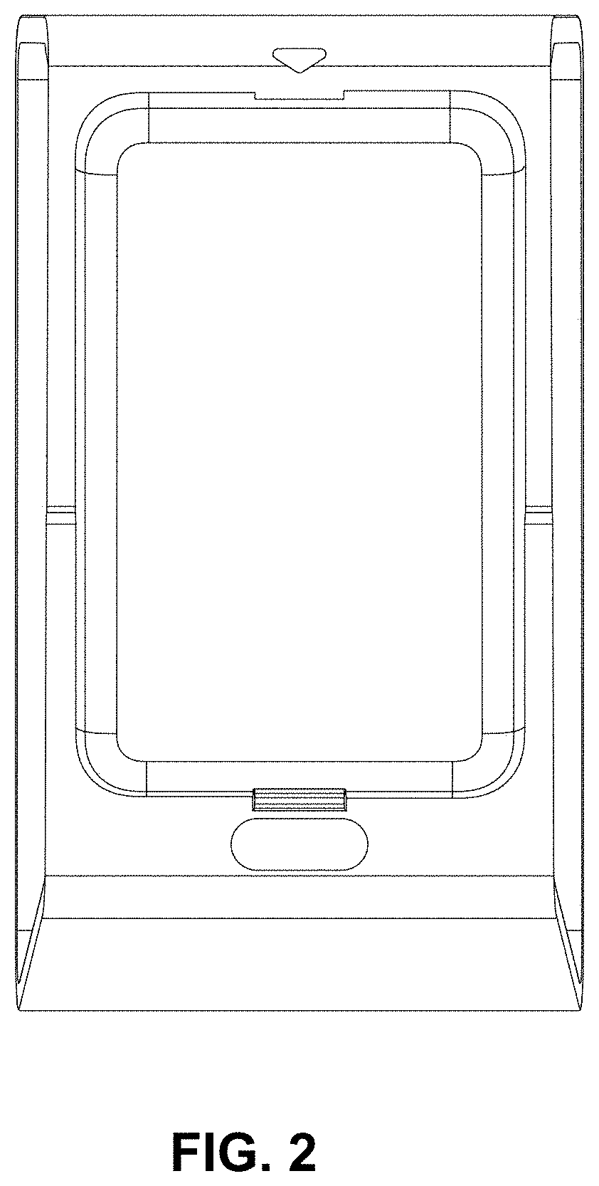
FIG. 2 is a front view of the invention illustrated in FIG. 1;
FIG. 3 is a back view of the invention illustrated in FIG. 1;
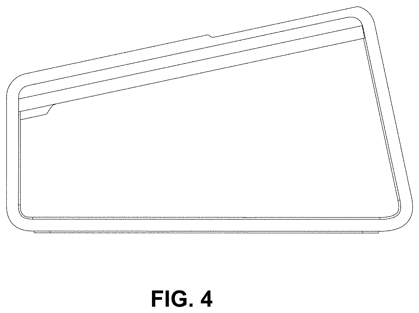
FIG. 4 is a right elevation view of the invention illustrated in FIG. 1;
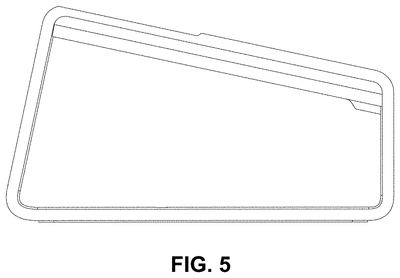
FIG. 5 is a left elevation view of the invention illustrated in FIG. 1;
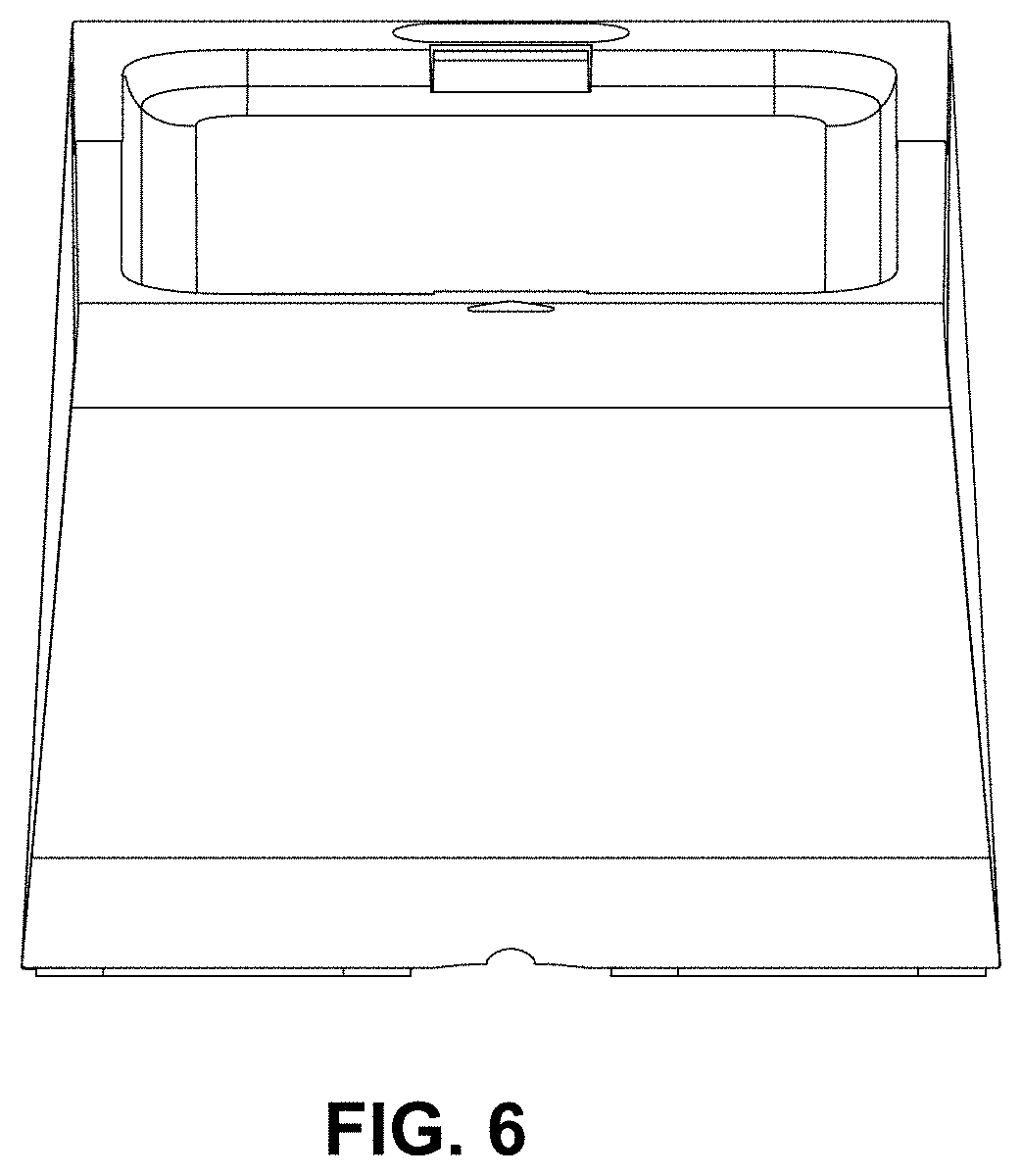
FIG. 6 is a top view of the invention illustrated in FIG. 1; and,
FIG. 7 is a bottom view of the invention illustrated in FIG. 1.
* * * * *
D00000
D00001
D00002
D00003
D00004
D00005
D00006
D00007
XML
uspto.report is an independent third-party trademark research tool that is not affiliated, endorsed, or sponsored by the United States Patent and Trademark Office (USPTO) or any other governmental organization. The information provided by uspto.report is based on publicly available data at the time of writing and is intended for informational purposes only.
While we strive to provide accurate and up-to-date information, we do not guarantee the accuracy, completeness, reliability, or suitability of the information displayed on this site. The use of this site is at your own risk. Any reliance you place on such information is therefore strictly at your own risk.
All official trademark data, including owner information, should be verified by visiting the official USPTO website at www.uspto.gov. This site is not intended to replace professional legal advice and should not be used as a substitute for consulting with a legal professional who is knowledgeable about trademark law.