Thermal imaging sensor
Elrod , et al. November 17, 2
U.S. patent number D902,057 [Application Number D/694,614] was granted by the patent office on 2020-11-17 for thermal imaging sensor. This patent grant is currently assigned to Fluke Electronics Corporation. The grantee listed for this patent is Fluke Electronics Corporation. Invention is credited to Jeffrey Elrod, Aaron Laho.
| United States Patent | D902,057 |
| Elrod , et al. | November 17, 2020 |
Thermal imaging sensor
Claims
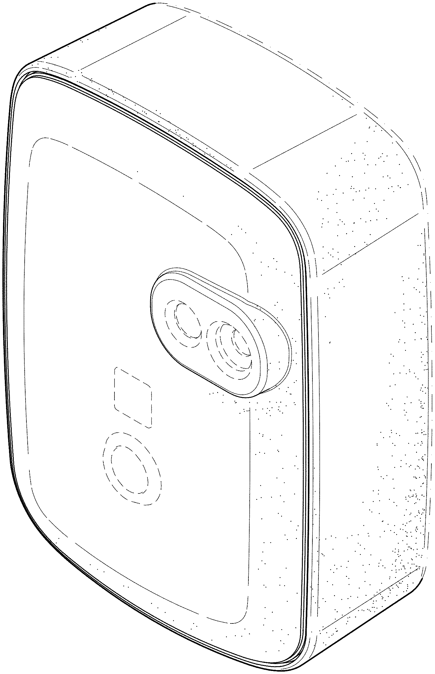
CLAIM The ornamental design for a thermal imaging sensor, as shown and described.
| Inventors: | Elrod; Jeffrey (Seattle, WA), Laho; Aaron (Big Lake, MN) | ||||||||||
|---|---|---|---|---|---|---|---|---|---|---|---|
| Applicant: |
|
||||||||||
| Assignee: | Fluke Electronics Corporation
(Everett, WA) |
||||||||||
| Appl. No.: | D/694,614 | ||||||||||
| Filed: | June 12, 2019 |
Related U.S. Patent Documents
| Application Number | Filing Date | Patent Number | Issue Date | ||
|---|---|---|---|---|---|
| 29595984 | Mar 3, 2017 | D854430 | |||
| Current U.S. Class: | D10/52; D16/203 |
| Current International Class: | 1004 |
| Field of Search: | ;D10/47,52,70,30-32,38,40,41,46,79,106.5,106.6,106.92,106.94,114.6,123,125,126,128,131 ;D11/1-4,93,94 ;D14/138,144,341,344,358,485 ;D24/167,169,186,187 ;D16/203 |
References Cited [Referenced By]
U.S. Patent Documents
| D319600 | September 1991 | Kaiser et al. |
| D538187 | March 2007 | Liu |
| D560193 | January 2008 | Sung et al. |
| D562306 | February 2008 | Jeong et al. |
| D651632 | January 2012 | Kim |
| D653566 | February 2012 | Gonzales et al. |
| D663644 | July 2012 | Ten Wolde |
| D675584 | February 2013 | Sharp |
| D683634 | June 2013 | Hayakawa et al. |
| D688635 | August 2013 | Ni et al. |
| D693342 | November 2013 | Sip et al. |
| D722983 | February 2015 | Paredes |
| D725324 | March 2015 | Schrick |
| D733596 | July 2015 | Goodner et al. |
| D744451 | December 2015 | Takahata |
| D750992 | March 2016 | Perez |
| D761138 | July 2016 | Manabe et al. |
| D765530 | September 2016 | Scalisi |
| D782926 | April 2017 | Hojo et al. |
| D794695 | August 2017 | Zhang |
| D795833 | August 2017 | Zhou |
| D797100 | September 2017 | Wieser et al. |
| D797836 | September 2017 | Li |
| D798177 | September 2017 | Siminoff |
| D802132 | November 2017 | Ohno et al. |
| D803919 | November 2017 | Jeong |
| D808828 | January 2018 | Behar et al. |
| D810738 | February 2018 | Cho |
| D810805 | February 2018 | Loew |
| D816520 | May 2018 | Elrod |
| D822518 | July 2018 | Siminoff |
| D822519 | July 2018 | Siminoff |
| D822520 | July 2018 | Siminoff |
| D830446 | October 2018 | Muhlenkamp |
| D830871 | October 2018 | Siminoff |
| D842136 | March 2019 | Jang |
| D848891 | May 2019 | Paredes |
| D854430 | July 2019 | Elrod |
| D857077 | August 2019 | Arens |
| D858338 | September 2019 | Yu |
| D860848 | September 2019 | Park |
| D861765 | October 2019 | Muhlenkamp |
| D863990 | October 2019 | Hu |
| D866356 | November 2019 | Elrod |
| D867421 | November 2019 | Morishita |
| D869541 | December 2019 | Wang |
| D869965 | December 2019 | Taniguchi |
| D870791 | December 2019 | Hasani |
| D871240 | December 2019 | Burns |
| D871483 | December 2019 | Chang |
| D873828 | January 2020 | Zhou |
| D874531 | February 2020 | Chen |
| D874532 | February 2020 | Chen |
| D874535 | February 2020 | Park |
| D874536 | February 2020 | Park |
| D874550 | February 2020 | Loew |
| D874551 | February 2020 | Loew |
| D874552 | February 2020 | Loew |
| D875158 | February 2020 | Wang |
| D875809 | February 2020 | Huang |
| D876514 | February 2020 | Siminoff |
| D876518 | February 2020 | Tran |
| D876519 | February 2020 | Yannay |
Other References
|
Fluke 3550 FC Thermal Imaging Sensor, posted on youtube.com, posted date Aug. 24, 2017, [online], [site visited Mar. 12, 2018], available from internet, URL: https://www.youtube.com/watch?v=RJT7oBZnnw0w (Year: 2017). cited by examiner. |
Primary Examiner: Stout; Michael C
Assistant Examiner: Butac; Fritzgerald L
Attorney, Agent or Firm: Seed Intellectual Property Law Group LLP
Description
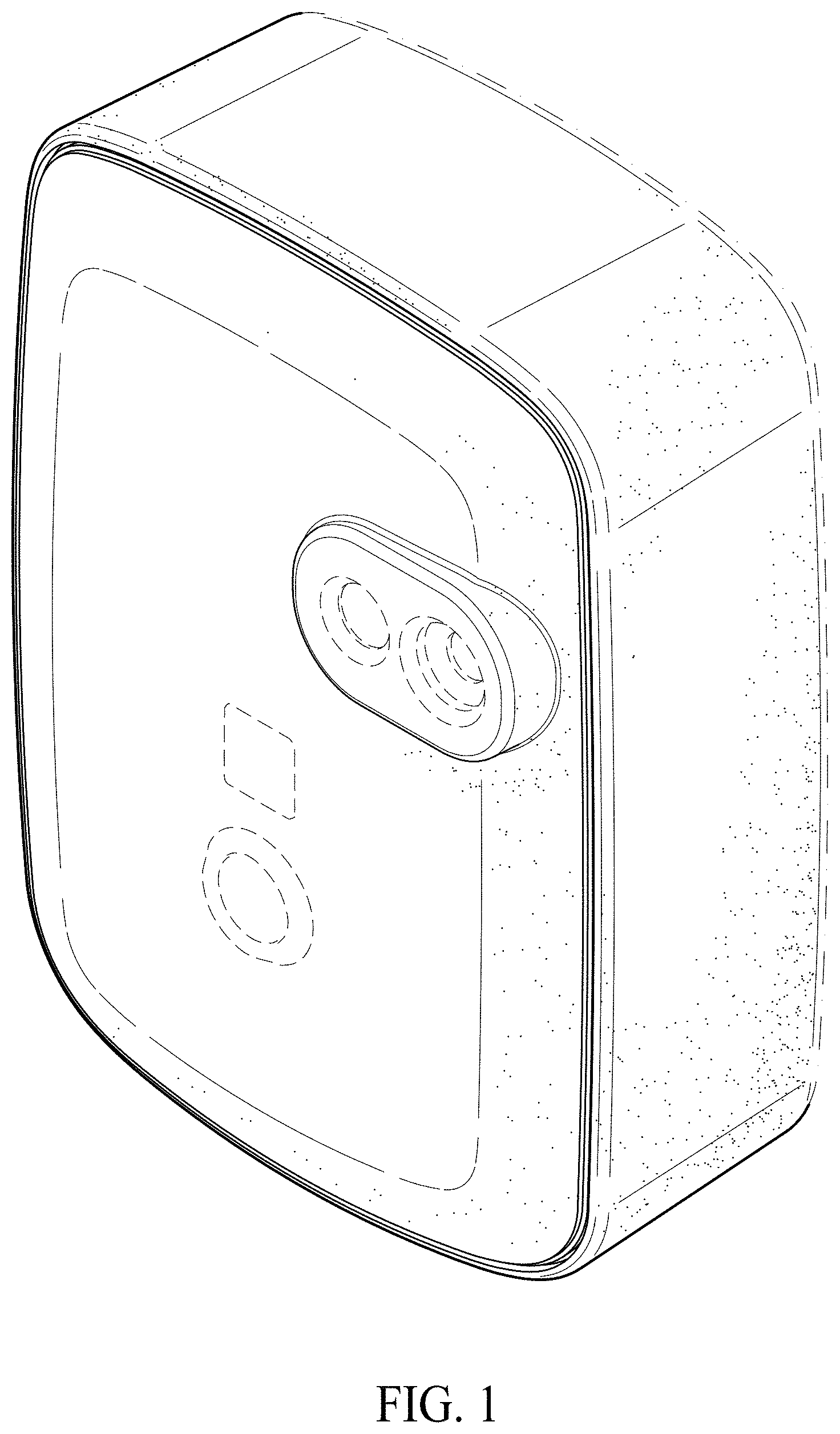
FIG. 1 is a top front right perspective view of a thermal imaging sensor showing our new design.
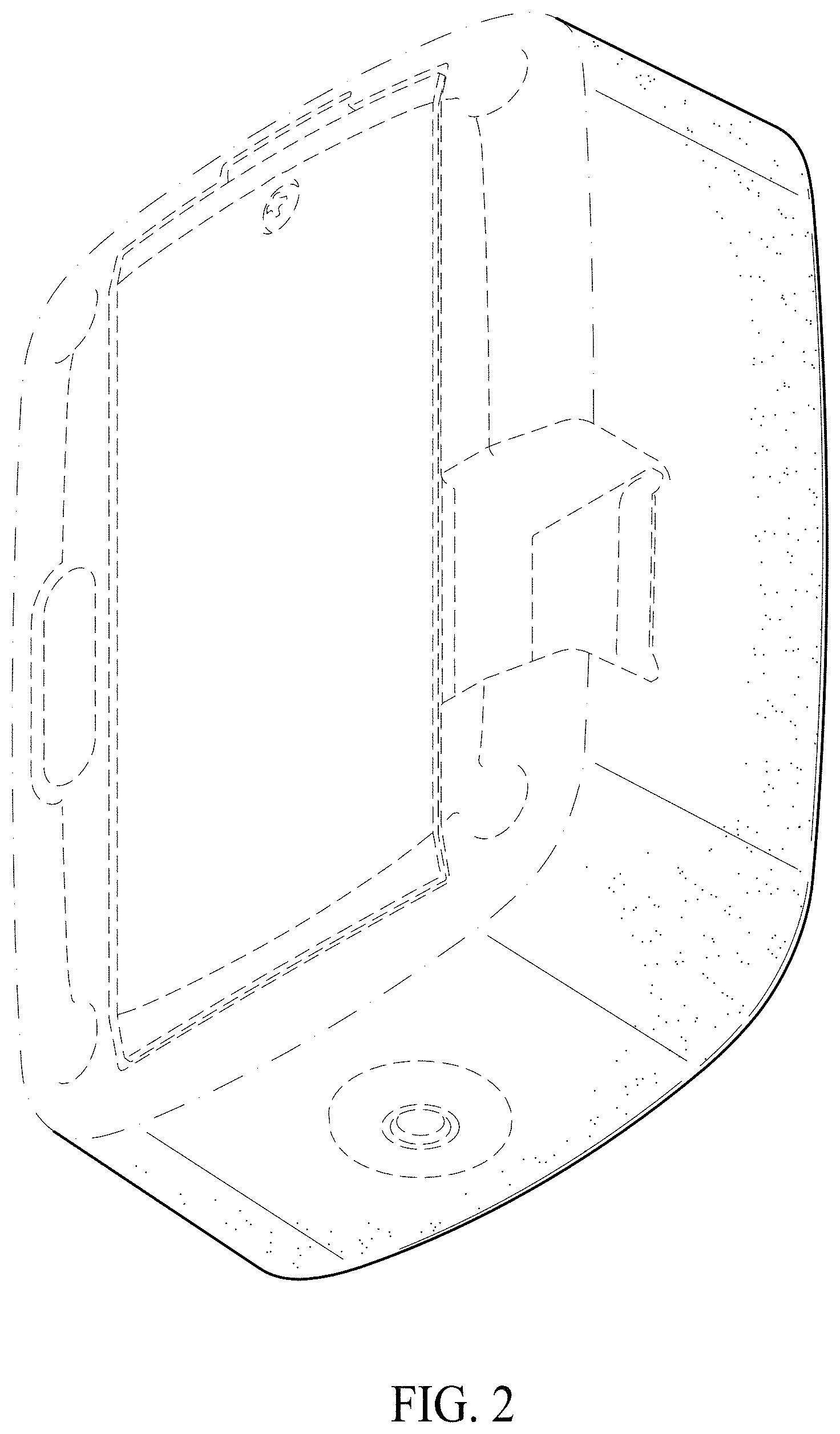
FIG. 2 is a bottom rear left perspective view thereof.
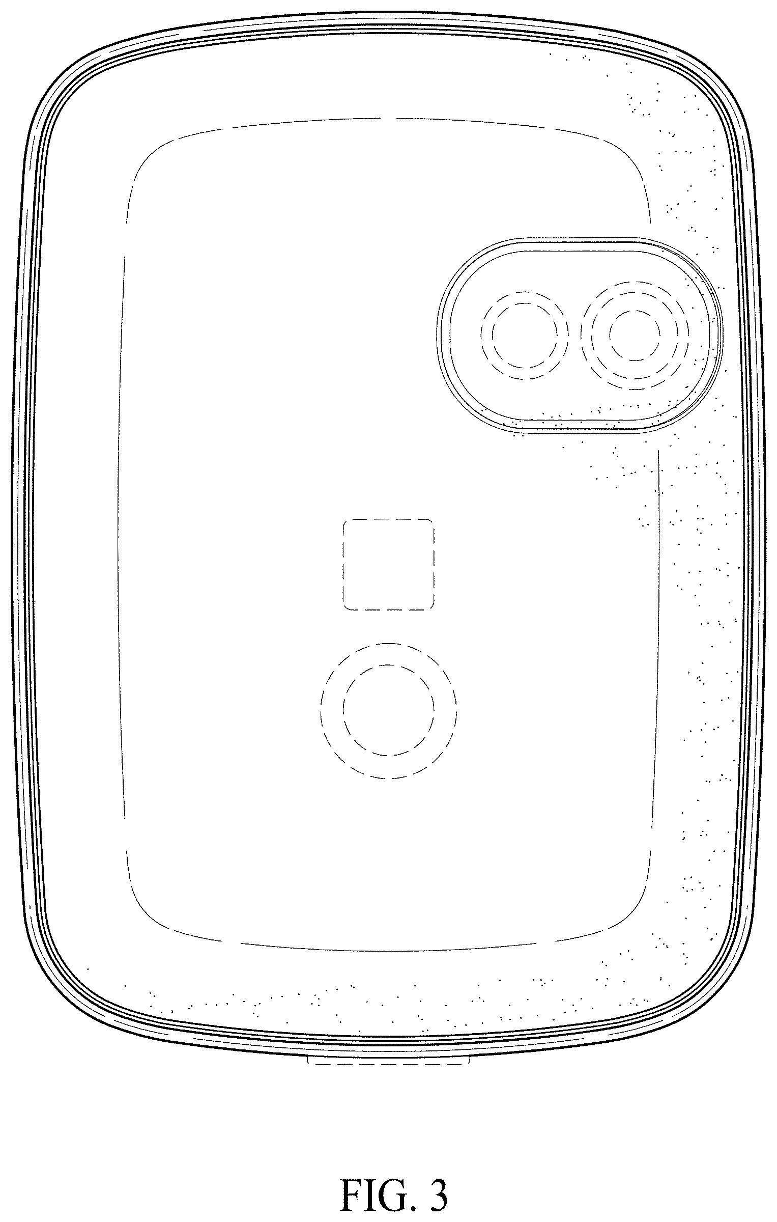
FIG. 3 is a front elevation view thereof.
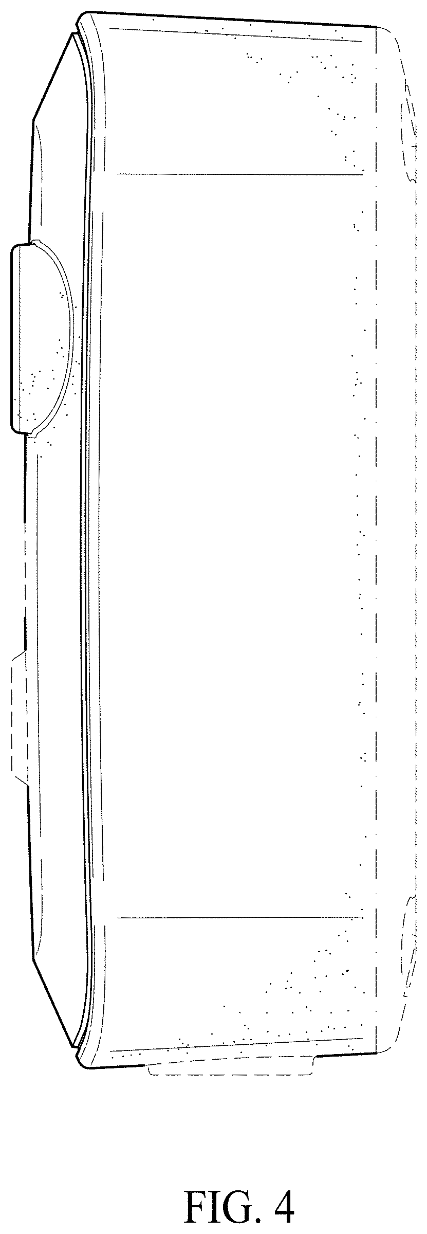
FIG. 4 is a right side elevation view thereof.
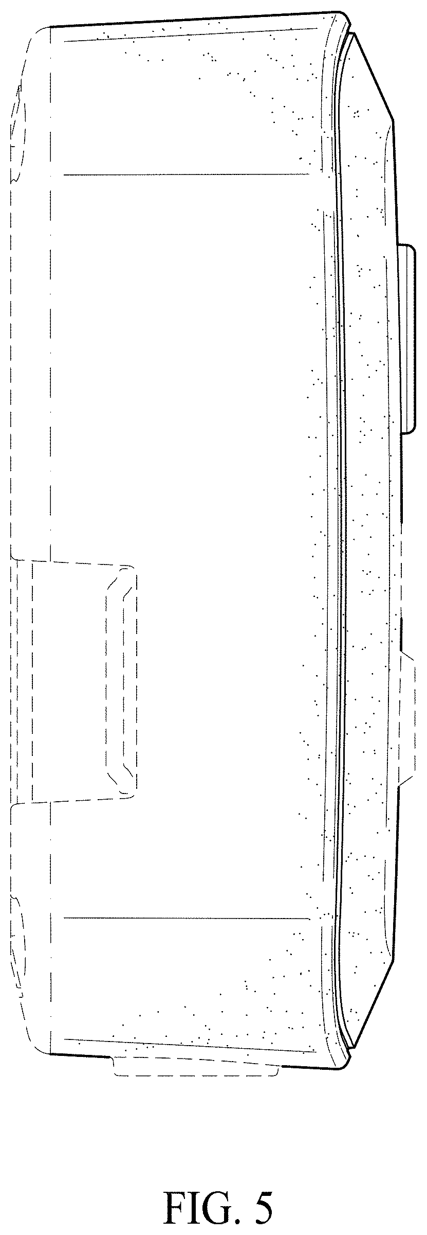
FIG. 5 is a left side elevation view thereof.
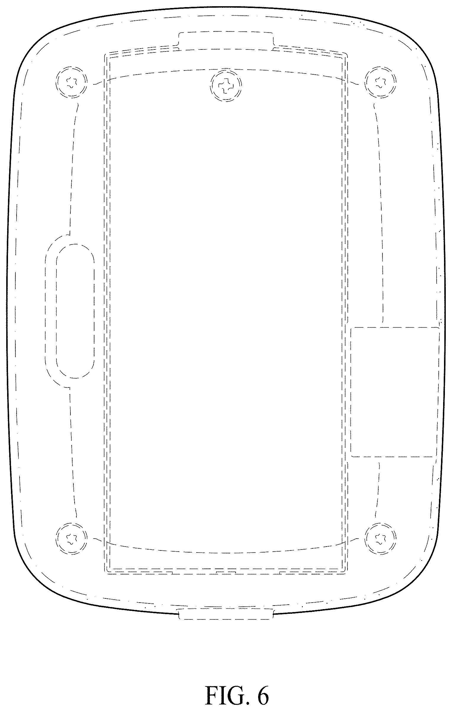
FIG. 6 is a rear elevation view thereof.
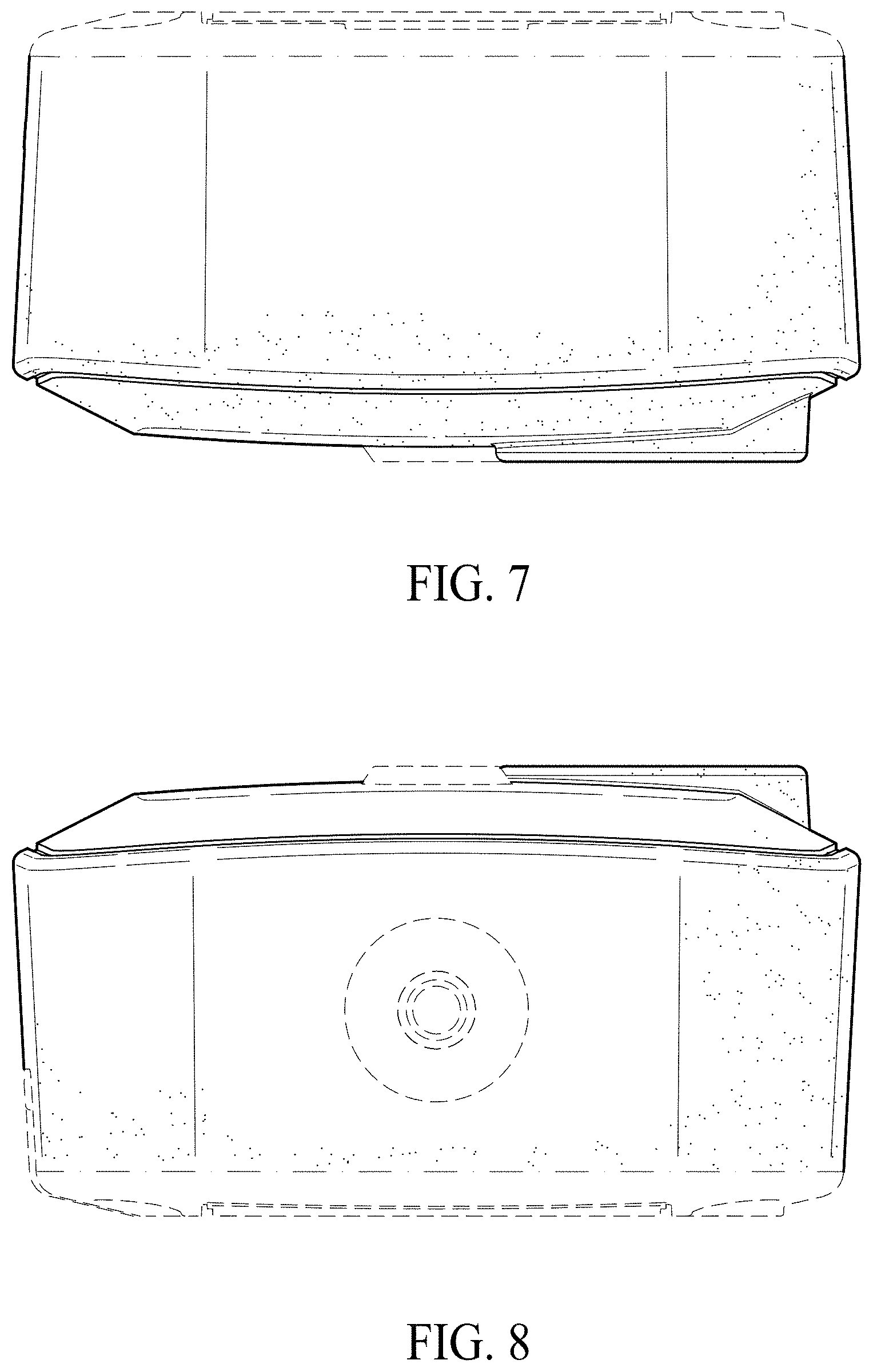
FIG. 7 is a top plan view thereof; and,
FIG. 8 is a bottom plan view thereof.
The broken lines in the figures show portions of the thermal imaging sensor that form no part of the claimed design. The dash-dot line defines the bounds of the claimed design and forms no part thereof. The stippling constitutes surface shading that merely clarifies contours of the surface of the claimed design and does not indicate surface texture, material, or color.
* * * * *
References
D00000
D00001
D00002
D00003
D00004
D00005
D00006
D00007
XML
uspto.report is an independent third-party trademark research tool that is not affiliated, endorsed, or sponsored by the United States Patent and Trademark Office (USPTO) or any other governmental organization. The information provided by uspto.report is based on publicly available data at the time of writing and is intended for informational purposes only.
While we strive to provide accurate and up-to-date information, we do not guarantee the accuracy, completeness, reliability, or suitability of the information displayed on this site. The use of this site is at your own risk. Any reliance you place on such information is therefore strictly at your own risk.
All official trademark data, including owner information, should be verified by visiting the official USPTO website at www.uspto.gov. This site is not intended to replace professional legal advice and should not be used as a substitute for consulting with a legal professional who is knowledgeable about trademark law.